Table of Contents
Advertisement
Available languages
Available languages
Harbor Breeze® is a registered trademark of
LF, LLC. All Rights Reserved.
ATTACH YOUR RECEIPT HERE
Serial Number
Questions, problems, missing parts? Before returning to your retailer, call our customer
service department at
5 p.m., EST, Friday.
EB15412
Purchase Date
1-800-643-0067, 8 a.m. - 6 p.m., EST, Monday - Thursday, 8 a.m. -
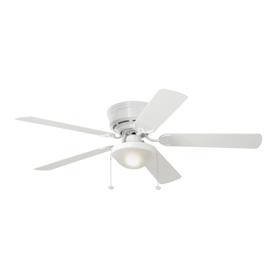
ARMITAGE CEILING FAN
Lowes.com/harborbreeze
1
ITEM #0020776
MODEL #CC52WW5C
Español p. 18
4010239
Advertisement
Chapters
Table of Contents

Related Manuals for Harbor Breeze ARMITAGE CC52WW5C


Summary of Contents for Harbor Breeze ARMITAGE CC52WW5C
- Page 1 ITEM #0020776 ARMITAGE CEILING FAN MODEL #CC52WW5C Español p. 18 Harbor Breeze® is a registered trademark of LF, LLC. All Rights Reserved. ATTACH YOUR RECEIPT HERE 4010239 Serial Number Purchase Date Questions, problems, missing parts? Before returning to your retailer, call our customer service department at 1-800-643-0067, 8 a.m.
-
Page 2: Table Of Contents
TABLE OF CONTENTS Safety Information .......................2 Package Contents .......................4 Hardware Contents ..........................5 Preparation ..........................5 Initial Installation ........................6 Wiring ..........................8 Final Installation ........................10 Operating Instructions .......................12 Care and Maintenance ......................14 Troubleshooting........................15 Limited Lifetime Warranty ....................16 Replacement Parts List .....................17 SAFETY INFORMATION READ AND SAVE THESE INSTRUCTIONS Please read and understand this entire manual before attempting to assemble, install or operate the product. - Page 3 SAFETY INFORMATION DANGER When using an existing outlet box, make sure the outlet box is securely attached to the building structure and can support the full weight of the fan. Failure to do this can result in serious injury or death.
-
Page 4: Package Contents
PACKAGE CONTENTS PART DESCRIPTION QUANTITY PART DESCRIPTION QUANTITY Mounting Bracket Mounting Bracket Nut (preassembled) Shade Fitter Plate Lock Washer Motor Housing (preassembled) + 1 extra Motor Assembly Motor Screw Glass Shade (preassembled) + 1 extra Blade Arm Motor Housing Mounting Blade Screw (preassembled) Pull Chain Extension... -
Page 5: Hardware Contents
HARDWARE CONTENTS (shown actual size) Blade Fiber Screw Blade E3 Wire Washer Connector Qty. 15 + 1 extra Qty. 15 + 1 extra Qty. 4 PREPARATION Before beginning assembly of product, make sure all parts are present. Compare parts with package contents list and hardware contents list. -
Page 6: Initial Installation
INITIAL INSTALLATION Turn off circuit breakers and wall switch to the fan supply line leads. DANGER: Failure to disconnect power supply prior to installation may result in serious injury or death. This fan can be mounted as a flushmount on a regular (no-slope) ceiling only. - Page 7 INITIAL INSTALLATION Secure mounting bracket (A) to outlet box using screws, spring washers, and flat washers provided with the outlet box. *Note: It is very important that you use the proper hardware when installing the mounting bracket (A) as this will support the fan. Remove motor screws (M) and lock washers (L) from underside of motor -- save motor screws (M) and lock washers (L) to attach...
-
Page 8: Wiring
WIRING WARNING: To reduce the risk of fire, electrical shock, or personal injury, wire connectors provided with this fan are designed to accept only one 12-gauge house wire and two lead wires from the fan. If your house wire is larger than 12-gauge or there is more than one house wire to connect to the corresponding fan lead wires, consult an electrician for the proper size wire connectors to use. - Page 9 WIRING 1c. FAN AND LIGHT CONTROLLED BY TWO FAN AND LIGHT CONTROLLED BY TWO WALL SWITCHES FAN AND LIGHT CONTROLLED BY TWO WALL SWITCHES WALL SWITCHES: If you intend to control the BLACK (WALL SWITCH FOR LIGHT) fan and light with separate wall switches, BLACK (WALL SWITCH) connect BLACK wire from fan to BLACK wire 120 V Power...
-
Page 10: Final Installation
FINAL INSTALLATION Remove motor assembly (D) from "J" hook and lift motor assembly (D) to mounting bracket (A). Align holes and secure motor assembly (D) with mounting bracket flat washers (J) and mounting bracket nuts (K) previously removed (Step 3, page 6). Temporarily lift motor housing (C) to mounting bracket (A) to determine which two motor housing mounting screws (N) in sides of mounting bracket... - Page 11 FINAL INSTALLATION Locate motor screws (M) and lock washers (L) removed in Step 5 on page 7. Insert two motor screws (M) along with lock washers (L) through one blade arm (F) to attach blade arm (F) to motor. Tighten motor screws (M) securely.
-
Page 12: Operating Instructions
FINAL INSTALLATION Align slots on glass shade (E) with protrusions on the inside of the shade fitter plate (B). Turn glass shade (E) to the right (clockwise) until it no longer turns. NOTE: Pull down gently on the glass shade (E) to make sure that it is secured completely. - Page 13 OPERATING INSTRUCTIONS The pull chain located to the left of the reverse switch is used to turn the light ON or OFF. Use the fan reverse switch, located on the switch housing, to optimize your fan for seasonal performance. A ceiling fan will allow you to raise your thermostat setting in summer and lower your thermostat setting in winter without feeling a difference in your comfort.
-
Page 14: Care And Maintenance
OPERATING INSTRUCTIONS 3C. IMPORTANT: Reverse switch must be set 3 3C either completely UP or completely DOWN for fan to function. If the reverse switch is set in the middle position (Fig. 3C), fan will not operate. CARE AND MAINTENANCE At least twice each year, lower motor housing (C) to check motor assembly (D), and then tighten all screws on the fan. -
Page 15: Troubleshooting
TROUBLESHOOTING WARNING: Before beginning work, shut off the power supply to avoid electrical shock. PROBLEM POSSIBLE CAUSE CORRECTIVE ACTION Fan does not move. 1. Reverse switch not engaged. 1. Push switch firmly either up or down. 2. Power is off or fuse is blown. 2. -
Page 16: Limited Lifetime Warranty
LIMITED LIFETIME WARRANTY The distributor warrants this fan to be free from defects in workmanship and materials present at time of shipment from the factory for Lifetime limited from the date of purchase. This warranty applies only to the original purchaser. The distributor agrees to correct any defect at no charge or, at our option, replace the ceiling fan with a comparable or superior model. -
Page 17: Replacement Parts List
1-800-643-0067, 8 a.m. - 6 p.m., EST, Monday - Thursday, 8 a.m. - 5 p.m., EST, Friday. PART DESCRIPTION PART# 020776-A Mounting Bracket 020776-F Blade Arm 020776-G Blade Printed in China Harbor Breeze® is a registered trademark of LF, LLC. All Rights Reserved. Lowes.com/harborbreeze JMLI1508... -
Page 18: Ventilador De Techo
ARTÍCULO #0020776 VENTILADOR DE TECHO ARMITAGE MODELO #CC52WW5C Harbor Breeze® es marca registrada de LF, LLC. Reservados todos los derechos. ADJUNTE SU RECIBO AQUÍ 4010239 Número de serie Fecha de compra ¿Preguntas, problemas, piezas faltantes? Antes de volver a la tienda, llame a nuestro Departamento de Servicio al Cliente al 1-800-643-0067, de lunes a jueves de 8 a.m. -
Page 19: Información De Seguridad
INDICE DE MATERIAS Información de seguridad ....................19 Contenido del paquete .......................21 Aditamentos ..........................22 Preparación ............................22 Instalación inicial ........................23 Cableado ..........................25 Instalación final ........................27 Instrucciones de funcionamiento ..................29 Cuidado y mantenimiento ....................31 Solución de problemas ......................32 Garantía limitada de por vida ....................33 Lista de piezas de repuesto ....................34 INFORMACION DE SEGURIDAD LEA Y GUARDE ESTAS INSTRUCCIONES... - Page 20 INFORMACIÓN DE SEGURIDAD PELIGRO Si utiliza una caja de salida existente, asegúrese de que esté bien sujeta a la estructura del edificio y que pueda sostener el peso del ventilador. El incumplimiento de dicho paso podría provocar lesiones graves o la muerte. La estabilidad de la caja de salida es fundamental para minimizar el tambaleo y el ruido en el ventilador una vez que la instalación esté...
-
Page 21: Contenido Del Paquete
CONTENIDO DEL PAQUETE PIEZA DESCRIPCIÓN CANTIDAD PIEZA DESCRIPCIÓN CANTIDAD Abrazadera de montaje Tuerca de la abrazadera de montaje (preensamblada) Placa de soporte de la pantalla Arandela de seguridad (preensamblada) + 1 adicional Carcasa del motor Tornillo del motor Ensamble del motor (preensamblado) + 1 adicional Pantalla de vidrio... -
Page 22: Aditamentos
ADITAMENTOS (se muestran en tamaño real) Tornillo Arandela para aspa para aspa Conector de fibra de cables E3 Cant. 15 + 1 adicional Cant. 15 Cant. 4 + 1 adicional PREPARACIÓN Antes de comenzar a ensamblar el producto, asegúrese de tener todas las piezas. Compare las piezas con la lista del contenido del paquete y la lista de aditamentos. -
Page 23: Instalación Inicial
INSTALACIÓN INICIAL Interrumpa el suministro de energía del ventilador apagando los interruptores de circuito y el interruptor de pared. PELIGRO: Si no interrumpe el suministro de electricidad antes de la instalación, pueden producirse lesiones graves o la muerte. Este ventilador se puede montar al ras en un techo regular (sin inclinación) solamente. - Page 24 INSTALACIÓN INICIAL 4. Asegure la abrazadera de montaje (A) a la caja de salida con los tornillos, las arandelas de resorte, y las arandelas planas provistos con la caja de salida. *Nota: Es muy importante que use los aditamentos adecuados para instalar la abrazadera de montaje (A) ya que ésta soportará...
-
Page 25: Cableado
CABLEADO ADVERTENCIA: Para reducir el riesgo de incendios, descargas eléctricas o lesiones personales, los conectores de cables proporcionados con este ventilador están diseñados para soportar solo un conductor de la casa de calibre 12 y dos cables conductores del ventilador. Si el conductor de la casa es de un calibre superior a 12 o hay más de un conductor de la casa para conectar a los cables correspondientes del ventilador, pregúntele a un electricista cuál es el tamaño adecuado de los conectores de cables que debe utilizar. - Page 26 CABLEADO 1c. VENTILADOR Y LUZ CONTROLADOS POR DOS VENTILADOR Y LUZ CONTROLADOS POR DOS INTERRUPTORES DE PARED INTERRUPTORES DE PARED: Si desea controlar el NEGRO (INTERRUPTOR DE PARED PARA LA LUZ) ventilador y la luz con interruptores de pared separados, conecte el conductor NEGRO del ventilador al conductor Alimentación NEGRO (INTERRUPTOR DE PARED)
-
Page 27: Instalación Final
INSTALACIÓN FINAL 1. Retire el ensamble del motor (D) del gancho en forma de "J" y levante el ensamble del motor (D) hasta la abrazadera de montaje (A). Alinee los orificios y fije el ensamble del motor (D) con las arandelas planas de la abrazadera de montaje (J) y las tuercas de la abrazadera de montaje (K) que retiró... - Page 28 INSTALACIÓN FINAL Localice los tornillos del motor (M) y las arandelas de seguridad (L) que se retiraron en el Paso 5 de la página 24. Inserte dos tornillos del motor (M) junto con las arandelas de seguridad (L) a través de un brazo para las aspas (F) para fijar el brazo del aspa (F) al motor.
-
Page 29: Instrucciones De Funcionamiento
INSTALACIÓN FINAL 7. Alinee las ranuras en la pantalla de vidrio (E) con las protuberancias en la placa de soporte de la pantalla (B). Gire la pantalla de vidrio (E) hacia la derecha (en dirección de las manecillas del reloj) hasta que ya no gire. - Page 30 INSTRUCCIONES DE FUNCIONAMIENTO La cadena de tiro ubicada a la izquierda del interruptor de reversa se utiliza para ENCENDER o APAGAR la luz. Utilice el interruptor de reversa del ventilador, ubicado en la carcasa del interruptor, para optimizar el rendimiento de su ventilador según la estación del año.
-
Page 31: Cuidado Y Mantenimiento
INSTRUCCIONES DE FUNCIONAMIENTO 3C. IMPORTANTE: El interruptor de reversa se 3 3C debe configurar ya sea completamente HACIA ARRIBA o completamente HACIA ABAJO para que funcione el ventilador. Si el interruptor de reversa se configura en la posición del medio (Fig. -
Page 32: Solución De Problemas
SOLUCIÓN DE PROBLEMAS ADVERTENCIA: antes de comenzar cualquier trabajo, desconecte el suministro de electricidad para evitar descargas eléctricas. PROBLEMA CAUSA POSIBLE ACCION CORRECTIVA El ventilador no se El interruptor de reversa no está 1. Mueva firmemente el interruptor mueve. activado. hacia arriba o hacia abajo. -
Page 33: Garantía Limitada De Por Vida
SOLUCIÓN DE PROBLEMAS PROBLEMA CAUSA POSIBLE ACCION CORRECTIVA Los conductores de la caja de 2. Revise los conductores de la salida no están bien conectados. caja de salida y, si es necesario, vuelva a conectarlos de acuerdo con las instrucciones de las páginas 25 y 26. -
Page 34: Lista De Piezas De Repuesto
8 a.m. a 6 p.m., y los viernes de 8 a.m. a 5 p.m., hora estándar del Este. PIEZA DESCRIPCION PIEZA # Abrazadera de montaje 020776-A Brazo del aspa 020776-F Aspa 020776-G Impreso en China ® Harbor Breeze es una marca registrada de LF, LLC. Todos los derechos reservados. Lowes.com/harborbreeze...
Need help?
Do you have a question about the ARMITAGE CC52WW5C and is the answer not in the manual?
Questions and answers