Table of Contents
Advertisement
Quick Links
Advertisement
Chapters
Table of Contents

Subscribe to Our Youtube Channel
Related Manuals for Innovative Technology NV11


Summary of Contents for Innovative Technology NV11
- Page 1 NV11 MANUAL SET...
- Page 2 NV11 MANUAL SET INTRODUCTION...
- Page 3 NV11 Manual Set - Introduction MANUAL AMENDMENTS Document Base Details Spec. Used Issue Receipt Comments Date Date GA963-1 09/09/10 29/07/11 GA138 01/11/10 22/01/11 GA959 29/03/11 29/07/11 Amendment Details Rev. Date Amendment Details Issued by 19/04/12 First Issue Copyright © Innovative Technology Ltd 2012...
- Page 4 NV11 Manual Set - Introduction NV11 MANUAL SET - INTRODUCTION COPYRIGHT LIMITED WARRANTY PRODUCT SAFETY INFORMATION INTRODUCTION FEATURES TYPICAL APPLICATIONS STRUCTURE OF THIS MANUAL SET WHICH SECTION IS RELEVANT TO ME? MAIN HEADQUARTERS Innovative Technology Ltd Derker Street – Oldham – England - OL1 4EQ Tel: +44 161 626 9999 Fax: +44 161 620 2090 E-mail: support@innovative-technology.co.uk...
- Page 5 Authorized Reseller, and extending for the length of time stipulated by Innovative Technology Ltd. A list of Innovative Technology Ltd offices can be found in every section of this manual set. If the product proves defective within the applicable warranty period, Innovative Technology Ltd will repair or replace the product.
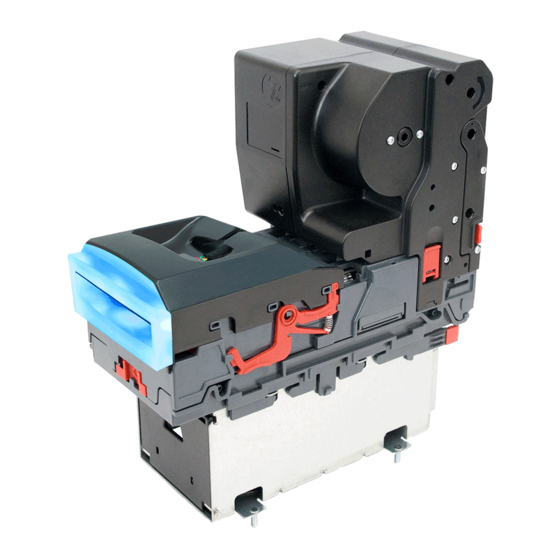
- Page 6 Cashbox The NV11 is a device that can accept, validate and store 300 or 600 bank notes of mixed denominations, and also has the capability of storing a further 30 notes in the Note Float module for future payout.
- Page 7 Uses a secure encrypted protocol for data transfer TYPICAL APPLICATIONS The NV11 validator can be used in a variety of situations where high security and high volume bank note acceptance, validation and payout are needed. Some typical applications are: AWP and SWP applications ...
- Page 8 – Typically used by a field service engineer who is maintaining the product. – This section contains the essential information that the field service engineer needs to clean, maintain and fault find an NV11 validator that is installed in a host machine. ITL Software Support Guide: ...
- Page 9 Software Implementation Guide: – Software engineers looking at how to implement the NV11 validator in their host machine, or design engineers looking at including the unit in their host machine. – The information in this section details the communications protocols, specific commands and interfaces used (eSSP and ccTalk).
- Page 10 SECTION NV11 MANUAL SET QUICK START CONFIGURATION GUIDE...
-
Page 11: Table Of Contents
NV11 Manual Set – Section 1 NV11 MANUAL SET – SECTION 1 QUICK START AND CONFIGURATION GUIDE Assembly Bezel Removal and Refitting Interfacing Connector and Pinouts Configuration Status Indicators Programming Technical Specifications NV11 Flash Codes 1.10 Fault Finding 1.11 Frequently Asked Questions Copyright ©... -
Page 12: Nv11 Manual Set - Section 1
NOT with earlier versions of the product Validator compatibility. (NV2 – NV5). Assembly Installing the NV11 is a simple operation, but note that the validator can only be installed horizontally: If the validator head Blanking plate has a blanking plate... - Page 13 NV11 Manual Set – Section 1 Always make sure the validator head has been Caution! opened BEFORE trying to remove the blanking Validator head MUST be plate – trying to remove the blanking plate with opened. the validator head closed will cause unit damage.
- Page 14 NV11 Manual Set – Section 1 The validator can be fitted with a standard or slide-on cashbox of 300 or 600 note capacity If not already attached, the validator can be fitted with a horizontal bezel of your choice. The cashbox is...
-
Page 15: Bezel Removal And Refitting
NV11 Manual Set – Section 1 There are many variants of bezel and cashbox type Information available for the NV11 validator. Please check the ITL website (www.innovative-technology.co.uk) for up to Check website for options. date information on the options available. -
Page 16: Interfacing
NV11 Manual Set – Section 1 Interfacing The connector needed to set up and interface with the NV11 validator is easily accessible on the side of the unit: Interface Connector Copyright © Innovative Technology Ltd 2012 GA963-2... -
Page 17: Connector And Pinouts
16 way connector. regardless of connection type. The connector is a 16 pin socket used to interface the NV11 to the host machine. The pin numbering of the socket is shown below, as well as an overview of the socket connections:... -
Page 18: Configuration
NV11 Manual Set – Section 1 Configuration The NV11 does not use DIP switches to configure the unit – configuration and setting is carried out by using a Configuration Button mounted on the front of the Note Float module: Note Float module... -
Page 19: Status Indicators
If there is a fault or other issue with the unit, the LEDs will flash as described in subsection 1.9. Programming Full details on programming the NV11 validator can be found in Section 3 of this manual set (ITL Software Support Guide). Copyright © Innovative Technology Ltd 2012... -
Page 20: Technical Specifications
NV11 Manual Set – Section 1 Technical Specifications The full technical specifications for the NV11 validator can be found in Section 6, Appendix B of this manual set. A brief summary is given here: DC Voltage Minimum Nominal Maximum Absolute limits 10.8 V... -
Page 21: Nv11 Flash Codes
NV11 Manual Set – Section 1 NV11 Flash Codes The NV11 validator has inbuilt fault detection facilities. If there is a configuration or other error either the Note Float module status LED, or the NV9USB validator head front bezel will flash in a particular sequence; a summary of the Flash Codes for both... - Page 22 NV11 Manual Set – Section 1 Note Float Module Flash Codes: Flashes Indicated Error Comments None Constant Remove trapped note from the flash Note Float module and press Note transport error (1 every the configuration button once second) Download new dataset /...
-
Page 23: Fault Finding
NV11 Manual Set – Section 1 1.10 Fault Finding Please use this flow chart with the Flash Codes in the previous sub-section as an aid to help resolve any configuration or start up problems you might have after installing the NV11 validator... - Page 24 NV11 Manual Set – Section 1 Check and clean the note path (see Section 2 of this manual set). Foreign objects in note path Check drive belts are fitted correctly and that there is no debris underneath the belts. Check voltage and current supplied to the validator are...
-
Page 25: Frequently Asked Questions
1.11 Frequently Asked Questions a. Why are there no DIP switches on the unit? The NV11 has no dipswitches. Configuring the unit is carried out by using the configuration button mounted on the front of the Note Float module – see subsection 1.5 of this manual for more information. - Page 26 Tel: +44 161 626 9999 Fax: +44 161 620 2090 E-mail: support@innovative-technology.co.uk Web site: www.innovative-technology.co.uk BRAZIL suporte@bellis-technology.com.br CHINA support@innovative-technology.co.uk GERMANY supportDE@innovative-technology.eu SPAIN supportES@innovative-technology.eu UNITED KINGDOM support@innovative-technology.co.uk UNITED STATES OF AMERICA supportusa@bellis-technology.com REST OF THE WORLD support@innovative-technology.co.uk Copyright © Innovative Technology Ltd 2012 GA963-2...
- Page 27 SECTION NV11 MANUAL SET FIELD SERVICE MANUAL...
- Page 28 NV11 Manual Set – Section 2 NV11 MANUAL SET – SECTION 2 FIELD SERVICE MANUAL Cleaning Fault Finding - Flash Codes Technical Specifications Fault Finding Flow Chart Frequently Asked Questions Spare Parts Copyright © Innovative Technology Ltd 2012 GA963-2...
-
Page 29: Nv11 Manual Set - Section 2
This section contains the essential information that the field engineer needs to clean, maintain and fault find an NV11 validator that is installed in a host machine. The NV11 validator has been designed to minimise any problems or performance variations over time. - Page 30 NV11 Manual Set – Section 2 Note path Lozenge release catch Lozenge Drive belts Note stacker Cash box spring plate Note Float module Cashbox Unless stated otherwise, you should disconnect WARNING! the power BEFORE carrying out any cleaning operations to avoid the risk of causing damage Disconnect power BEFORE to the validator.
- Page 31 NV11 Manual Set – Section 2 Ideally, you should also remove the Note Float module prior to cleaning the sensors. Removal is a very straightforward task: Do not attempt to disassemble the Note Float WARNING! module – there are no user serviceable parts...
- Page 32 NV11 Manual Set – Section 2 Front sensors Optical sensor Start sensor Rear sensor Optical sensor Examine the note paths, lozenge and note stacker for any dirt or debris, and carefully clear and wipe the surfaces of the note paths and lozenge with a soft lint free cloth that has been dampened with a water and mild detergent solution (i.e.
- Page 33 NV11 Manual Set – Section 2 When cleaning the recessed front sensor, use a Caution! small soft brush or cotton bud – do not use Be careful cleaning sensors. anything sharp or abrasive. Cleaning the belts is a simple operation. Ensure the validator is enabled (i.e. bezel lights are illuminated), then remove the bezel: b.
- Page 34 NV11 Manual Set – Section 2 Insert a piece of paper (which is narrower than the width between the two belts) in the centre of the note path to activate the drive motor Use a lint free cloth dampened...
- Page 35 NV11 Manual Set – Section 2 If the belts are worn or damaged, they should be replaced. This is a simple procedure, and is carried out as follows: Do not attempt to disassemble the validator WARNING! head or Note Float module – trying to do this...
-
Page 36: Fault Finding - Flash Codes
NV11 Manual Set – Section 2 Fault Finding - Flash Codes The NV11 validator has inbuilt fault detection facilities. If there is a configuration or other error either the Note Float module status LED, or the NV9USB validator head front bezel will flash in a particular sequence; a summary of the Flash Codes for both... - Page 37 NV11 Manual Set – Section 2 Note Float Module Flash Codes: Flashes Indicated Error Comments None Constant Remove trapped note from the flash Note Float module and press Note transport error (1 every the configuration button once second) Download new dataset /...
-
Page 38: Technical Specifications
NV11 Manual Set – Section 2 Technical Specifications The full technical specifications for the NV11 validator can be found in Section 6, Appendix B of this manual set. A brief summary is given here: DC Voltage Minimum Nominal Maximum Absolute limits 10.8 V... -
Page 39: Fault Finding Flow Chart
NV11 Manual Set – Section 2 Fault Finding Flow Chart Please use this flow chart with the Flash Codes in subsection 2.2 as an aid to help resolve any configuration or start up problems you might have after installing the... - Page 40 NV11 Manual Set – Section 2 Foreign objects in Check and clean the note path (see subsection 2.1 of note path this manual). Check voltage and current supplied to the validator are Acceptor runs slowly Incorrect supply within the tolerances specified in the Technical...
-
Page 41: Frequently Asked Questions
Section 1, subsection 1.5 of this manual set for more information. b. In what orientation can I use the NV11 validator? The NV11 can only be mounted horizontally - see Section 1, subsection 1.1 of this manual for more information on mounting the validator. Please check the ITL website to see the currently available range of cashboxes and bezels. - Page 42 Full details of the interface cable connector pinouts, connector types / makes and other related information can be found in Section 4 of this manual set. The user can obtain the following parts for the NV11 validator: ITL Part Number...
- Page 43 NV11 Manual Set – Section 2 ITL Part Number Description Details CN292 Interface cable Provides connection between DA2 and NV11 Copyright © Innovative Technology Ltd 2012 GA963-2...
- Page 44 NV11 Manual Set – Section 2 ITL Part Number Description Details CN392 Power and USB Communication Cable USB 2.0 Compliant Type A to 16 way header cable Copyright © Innovative Technology Ltd 2012 GA963-2...
- Page 45 NV11 Manual Set – Section 2 Bezels ITL Part Description Number PA189 Horizontal Bezel Assembly 69mm Fixed Width No image available PA268 Horizontal Bezel PA896 Horizontal Bezel Assembly Copyright © Innovative Technology Ltd 2012 GA963-2...
- Page 46 NV11 Manual Set – Section 2 Cashboxes Locking Cashbox PA186 Assembly (300L) Slide-on Cashbox PA192 Assembly (300S) Standard Cashbox PA898 Assembly Copyright © Innovative Technology Ltd 2012 GA963-2...
- Page 47 NV11 Manual Set – Section 2 There are many variants of bezel and cashbox type Information available for the NV11 validator. Please check the ITL website (www.innovative-technology.co.uk) for up to Check website for options. date information on the options available.
- Page 48 Tel: +44 161 626 9999 Fax: +44 161 620 2090 E-mail: support@innovative-technology.co.uk Web site: www.innovative-technology.co.uk BRAZIL suporte@bellis-technology.com.br CHINA support@innovative-technology.co.uk GERMANY supportDE@innovative-technology.eu SPAIN supportES@innovative-technology.eu UNITED KINGDOM support@innovative-technology.co.uk UNITED STATES OF AMERICA supportusa@bellis-technology.com REST OF THE WORLD support@innovative-technology.co.uk Copyright © Innovative Technology Ltd 2012 GA963-2...
- Page 49 SECTION NV11 MANUAL SET ITL SOFTWARE SUPPORT GUIDE...
- Page 50 NV11 Manual Set – Section 3 NV11 MANUAL SET – SECTION 3 ITL SOFTWARE SUPPORT GUIDE PiPS Software 3.1.1 Preparing for Installation 3.1.2 BV Interface Drivers 3.1.3 Installing the Drivers 3.1.4 Installing the PiPS Software 3.1.5 Starting the PiPS Software 3.1.6...
-
Page 51: Itl Software Support Guide
PiPS (Pay in Pay out System) is a software package developed by Innovative Technology Ltd to allow customers to carry out programming, setup and operational tasks on the full range of NV11 devices. 3.1.1 Preparing for Installation If you do not have the PiPS software on CD, you can easily download it from the Innovative Technology website. - Page 52 NV11 Manual Set – Section 3 Enter your login details here, or create a new account After logging in, the download screen will change slightly: Your user name will be displayed in the top right hand corner of the screen The padlock icon for each file will change from locked to unlocked.
- Page 53 NV11 Manual Set – Section 3 In this case, we want to download the PiPS software, so we click on the padlock icon opposite the ‘SMART PIPS (Pay In Pay Out System)’ filename: After clicking the link, a file download dialog box will appear – choose the option to...
- Page 54 NV11 Manual Set – Section 3 After choosing where to save the file, a file transfer dialog box will appear showing the progress of the file download: Copyright © Innovative Technology Ltd 2012 GA963-2...
-
Page 55: Bv Interface Drivers
NV11 Manual Set – Section 3 3.1.2 BV Interface Drivers After downloading the Validator Manager software, you will also need to download the Banknote Validator (BV) Interface drivers – two versions are available (32 bit and 64 bit) so choose the correct type for your operating system. Again, remember where you saved the file. - Page 56 NV11 Manual Set – Section 3 Extract the files to a convenient location – this might be an existing folder, or you may want to save them into a new folder. In this example, the BV Interface driver files are being saved into a folder called ‘Drivers’...
- Page 57 NV11 Manual Set – Section 3 Copyright © Innovative Technology Ltd 2012 GA963-2...
-
Page 58: Installing The Drivers
NV11 Manual Set – Section 3 3.1.3 Installing the Drivers There are several ways to communicate with the NV11 validator, which include using a direct connection from computer to validator with a CN392 validator to USB cable, or by using a special interface unit called a DA2. Use of the DA2 is not covered here –... - Page 59 NV11 Manual Set – Section 3 To use a USB connection with the NV11, a USB cable fitted with a 16 way connector on one end (ITL Part Number CN392) should be used. The CN392 cable fits into the 16 way connector and allows high speed programming and serial communications when used in SSP and ccTalk modes.
- Page 60 NV11 Manual Set – Section 3 Select this option as you already have the drivers Information Please make sure that you are using the V2 drivers for the installation. Only use V2 drivers Select this option as we have saved the...
- Page 61 NV11 Manual Set – Section 3 The next dialog box will ask you where to search for the drivers: Click the ‘Browse’ button to find the driver files (in this example C:\Drivers) Copyright © Innovative Technology Ltd 2012 GA963-2...
- Page 62 NV11 Manual Set – Section 3 Uncheck this option to speed up the installation Click the ‘Next’ button to install the drivers Copyright © Innovative Technology Ltd 2012 GA963-2...
- Page 63 NV11 Manual Set – Section 3 You may see a warning dialog saying that the drivers have not passed Windows logo testing – you can ignore this warning. Just click the ‘Continue Anyway’ button. Copyright © Innovative Technology Ltd 2012...
- Page 64 NV11 Manual Set – Section 3 Click the ‘Finish’ button to complete the installation Copyright © Innovative Technology Ltd 2012 GA963-2...
- Page 65 NV11 Manual Set – Section 3 After completing the driver installation you can check that the communications port has been installed correctly. Open Windows Device Manager, and click on the Plus symbol (+) next to the ‘Ports’ entry. This will expand the list of installed communications ports. You should see an entry for an ‘ITL BV Serial V2’...
-
Page 66: Installing The Pips Software
NV11 Manual Set – Section 3 3.1.4 Installing the PiPS Software Installing the PiPS software is very straightforward. Find the PiPS installation file you downloaded earlier, extract the installation file from the zipped file and double click the file (it has an .msi extension) – this will start the installation process: Copyright ©... - Page 67 NV11 Manual Set – Section 3 You can choose where you would like to install the software, or just accept the default location (as shown above). Clicking on the ‘Next’ button will then ask you to confirm the installation: Copyright © Innovative Technology Ltd 2012...
- Page 68 You can run the PiPS software by clicking the ‘Pay-in Pay-Out system’ menu entry; however, before you can use the PiPS software with an NV11 you will need to make sure that you have installed the BV interface drivers (as described earlier).
-
Page 69: Starting The Pips Software
The PiPS software is launched by clicking the ‘Pay-in Pay-out system’ entry in the ‘ITL Smart Tools’ menu group. The initial program screen looks like this: Make sure that the NV11 is powered up and the USB cable is connected before going any further. Copyright © Innovative Technology Ltd 2012... - Page 70 NV11 Manual Set – Section 3 Once the NV11 is connected, there are two ways to start the program operation: Click the ‘Start-up’ icon Click ‘Utilities’, then ‘Run PIPS System’ The PiPS software will then start to connect to the NV11.
- Page 71 NV11 Manual Set – Section 3 Once the NV11 unit has been found, two windows will appear on the screen: This window shows the installed currency, level and programming information for the connected NV11. This window will display all the...
-
Page 72: Preferences, Settings And Options
NV11 Normally, these preferences should not need changing. The settings and options for the NV11 vary depending whether the system is in the 'Run' or the 'Halt' state – generally the system will need to be halted before any changes to setup options can be made. - Page 73 NV11 Manual Set – Section 3 The main screen should look something like this: The various settings and options can be accessed from a right click when the mouse cursor is over any of the system device entries: Copyright © Innovative Technology Ltd 2012...
- Page 74 NV11 Manual Set – Section 3 Copyright © Innovative Technology Ltd 2012 GA963-2...
- Page 75 NV11 Manual Set – Section 3 Halt State Options Set Route To set the pay in route for inserted bank notes to either Cashbox or Note Float module, select the desired denomination(s) and click the required route. The system will send the commands to the device and store these preferences so that they will be set again on the next start-up.
- Page 76 NV11 Manual Set – Section 3 Run State If the system is in ‘Run’ state, the user will have clicked on the ‘Run’ button and the menu bar will look like this: Run State Options Set Route To set the pay in route for inserted bank notes to either Cashbox or Note Float module, select the desired domination(s) and click the required route.
-
Page 77: Updating Firmware And Datasets
Do not power off The NV11 validator firmware and dataset can be updated very easily using the PiPS software. The process uses NV9USB dataset files which can be downloaded from the Innovative Technology Ltd website:... - Page 78 NV11 Manual Set – Section 3 Copyright © Innovative Technology Ltd 2012 GA963-2...
- Page 79 NV11 Manual Set – Section 3 After selecting the dataset, a dialog will prompt you to save or open the file: select the Save option You can then choose where to save the file – choose a location that is convenient for you: Copyright ©...
- Page 80 NV11 Manual Set – Section 3 Once the dataset file is saved, unzip the file and you can then start the process to update the NV11 validator by connecting the USB cable and starting the PiPS software as described previously.
- Page 81 NV11 unit with – click the ‘Yes’ button to continue: A new dialog will then appear showing the update status: After the reset is complete, the NV11 validator will then be ready for use with the new currency.
-
Page 82: Tools
NV11 Manual Set – Section 3 Tools 3.3.1 Diagnostics There is a dedicated software diagnostics tool for use with the NV11 validator called ‘Bank Note Validator Diagnostics Tools’, and this software can be downloaded from the Innovative Technology Ltd website: When the file download dialog box appears, click the ‘Save’... - Page 83 ‘Shortcut to ITL Diagnostics.exe’ item near the top of the Windows Start menu. Make sure that the NV11 Validator is powered up and the USB cable is connected before starting the program. The main screen of the diagnostics tools software looks like this: When running the software for the first time, you need to set a few options.
- Page 84 NV11 Manual Set – Section 3 By selecting the ‘Serial Port’ item from the ‘Options’ menu you can define which serial port is being used to connect to the NV11 validator. After selecting this option, a new dialog box will open allowing you to choose the correct serial port.
- Page 85 NV11 Manual Set – Section 3 Select the ‘Diagnostics’ item from the ‘Utilities’ menu to start the diagnostics process (you can also start the diagnostics by clicking on the left hand icon below the menu bar) - this will open the Diagnostics screen: Click the ‘Start Diagnostic’...
- Page 86 NV11 Manual Set – Section 3 Diagnostics Pass: A summary of the validator type and Motor test results are shown in related information is displayed here. this window. The overall test result is displayed here. Sensor test results are shown in this window.
- Page 87 NV11 Manual Set – Section 3 Diagnostics Fail: Motor test results are shown in A summary of the validator type and this window – in this example all related information is displayed here. the motors have passed testing. The overall test result is displayed here.
-
Page 88: Connections
16 way connector. regardless of connection type. The connector is a 16 pin socket used to interface the NV11 to the host machine. The pin numbering of the socket is shown below, as well as an overview of the socket connections:... - Page 89 NV11 Manual Set – Section 3 NV11 SSP Interface: Name Type Description Output Serial data out (Tx) Factory use only Do not connect Input Serial data in (Rx) Factory use only Do not connect USB D+ Data USB Data +...
-
Page 90: Frequently Asked Questions
Frequently Asked Questions a. Why are there no DIP switches on the unit? The NV11 has no dipswitches. Configuring the unit is carried out using a configuration button mounted on the front of the Note Float module – see Section 1, subsection 1.5 of this manual set for more information. - Page 91 Tel: +44 161 626 9999 Fax: +44 161 620 2090 E-mail: support@innovative-technology.co.uk Web site: www.innovative-technology.co.uk BRAZIL suporte@bellis-technology.com.br CHINA support@innovative-technology.co.uk GERMANY supportDE@innovative-technology.eu SPAIN supportES@innovative-technology.eu UNITED KINGDOM support@innovative-technology.co.uk UNITED STATES OF AMERICA supportusa@bellis-technology.com REST OF THE WORLD support@innovative-technology.co.uk Copyright © Innovative Technology Ltd 2012 GA963-2...
- Page 92 SECTION NV11 MANUAL SET MECHANICAL AND ELECTRICAL MANUAL...
- Page 93 NV11 Manual Set – Section 4 NV11 MANUAL SET – SECTION 4 MECHANICAL AND ELECTRICAL MANUAL Introduction Assembly and Fitting Instructions Bezel Removal and Refitting Technical Specifications Cable Specifications Electrical Interfaces Configuration Button Programming Basic Operation 4.10 Spare Parts 4.11...
-
Page 94: Nv11 Manual Set - Section 4
Cashbox The NV11 is a device that can accept, validate and store 300 or 600 bank notes of mixed denominations, and also has the capability of storing a further 30 notes in the Note Float module for future payout. - Page 95 NV11 Manual Set – Section 4 The NV11 is a LIFO (Last In First Out) system. This means that only the last note in the Note Float module is available to be paid out or moved to the stacker. Any value note can be routed into the Note Float module using the ‘Set Routing’...
-
Page 96: Assembly And Fitting Instructions
NV11 Manual Set – Section 4 Assembly and Fitting Instructions Installing the NV11 is a simple operation, but note that the validator can only be installed horizontally: The NV11 validator is pin for pin compatible with Information the NV7 / NV8 / NV9 / NV10 series of validators, but NOT with earlier versions of the product Validator compatibility. - Page 97 NV11 Manual Set – Section 4 Side clips Remove the blanking plate by disengaging the two side clips and lifting the blanking plate upwards Close the validator head and then carefully fit the Note Rear cover Float module onto the...
- Page 98 NV11 Manual Set – Section 4 The validator can be fitted with a standard or slide-on cashbox of 300 or 600 note capacity If not already attached, the validator can be fitted with a horizontal bezel of your choice. The cashbox is...
-
Page 99: Bezel Removal And Refitting
NV11 Manual Set – Section 4 There are many variants of bezel and cashbox type Information available for the NV11 validator. Please check the ITL website (www.innovative-technology.co.uk) for up to Check website for options. date information on the options available. -
Page 100: Technical Specifications
The technical drawings which can be found at the end of this section show all the dimensional information needed to mount the unit. Technical Specifications The full technical specifications for the NV11 validator can be found in Section 6, Appendix B of this manual set. A brief summary is given here: DC Voltage... -
Page 101: Cable Specifications
NV11 Manual Set – Section 4 Cable Specifications The minimum specification for wire used in power cables for the NV11 validator is given here: Minimum Nominal Peak current Cable rating Insulation current rating rating rating 3.0 A 3.5 A 80 °C Do not use wire of an inferior specification, as this can cause operating problems with the validator. -
Page 102: Electrical Interfaces
NV11 Manual Set – Section 4 Electrical Interfaces Interface Connector The connector needed to set up and interface the NV11 validator is easily accessible on the side of the unit: Copyright © Innovative Technology Ltd 2012 GA963-2... - Page 103 16 way connector. regardless of connection type. The connector is a 16 pin socket used to interface the NV11 to the host machine. The pin numbering of the socket is shown below, as well as an overview of the socket connections:...
- Page 104 NV11 Manual Set – Section 4 NV11 SSP Interface: Name Type Description Output Serial data out (Tx) Factory use only Do not connect Input Serial data in (Rx) Factory use only Do not connect USB D+ Data USB Data +...
-
Page 105: Configuration Button
NV11 Manual Set – Section 4 Configuration Button The NV11 does not use DIP switches to configure the unit – configuration and setting is carried out by using a Configuration Button mounted on the front of the Note Float module:... -
Page 106: Programming
Full details on programming the NV11 validator using software can be found in Section 3 of this manual set (ITL Software Support Guide). It is not possible to program the NV11 by the use of a configuration card as this method of programming is not yet implemented. -
Page 107: Basic Operation
NV11 Manual Set – Section 4 Basic Operation The NV11 validator is a device that can accept, validate and store 300 or 600 bank notes of mixed denominations, and works with any NV9USB currency dataset created by Innovative Technology Ltd. - Page 108 NV11 Manual Set – Section 4 Note Float Module Flash Codes: Flashes Indicated Error Comments None Constant Remove trapped note from the flash Note Float module and press Note transport error (1 every the configuration button once second) Download new dataset /...
-
Page 109: Spare Parts
NV11 Manual Set – Section 4 4.10 Spare Parts ITL Part Number Description Details CN215 Ribbon interface cable Provides connection between DA2 and NV11 Comments: Please consult the tables on the next page for pin out and connector information. Copyright © Innovative Technology Ltd 2012... - Page 110 NV11 Manual Set – Section 4 CN215 Parts List Description Supplier Alternative 8 way 2 row 2.54mm pitch friction lock housing Leotronics 2652-2161 Molex 90142-0016 Tin plated crimp socket 22-24 AWG Leotronics 2653-2000 Molex 90119-0110 Black heat shrink sleeving 22 AWG stranded 4 core cable, PVC insulated...
- Page 111 NV11 Manual Set – Section 4 ITL Part Number Description Details CN292 Interface cable Provides connection between DA2 and NV11 Comments: Please consult the tables on the next page for pin out and connector information. Copyright © Innovative Technology Ltd 2012...
- Page 112 NV11 Manual Set – Section 4 CN292 Parts List Description Supplier Alternative 8 way 2 row 2.54mm pitch friction lock housing Leotronics 2652-2161 Molex 90142-0016 Tin plated crimp socket 22-24 AWG Leotronics 2653-2000 Molex 90119-0110 Black heat shrink sleeving 22 AWG stranded 4 core cable, PVC insulated...
- Page 113 NV11 Manual Set – Section 4 ITL Part Number Description Details CN392 Power and USB Communication Cable USB 2.0 Compliant Type A to 16 way header cable Comments: Please consult the tables on the next page for pin out and connector information.
- Page 114 NV11 Manual Set – Section 4 CN392 Parts List Description Supplier Alternative USB 2.0 lead with type A plug Molex 88728-3400 RS 324-8362 8 way 2 row 2.54mm pitch friction lock housing Molex 90142-0016 Leotronics 2652-2161 Gold plated crimp socket 22-24 AWG...
- Page 115 NV11 Manual Set – Section 4 Bezels ITL Part Description Number PA189 Horizontal Bezel Assembly 69mm Fixed Width No image available PA268 Horizontal Bezel PA896 Horizontal Bezel Assembly Copyright © Innovative Technology Ltd 2012 GA963-2...
- Page 116 NV11 Manual Set – Section 4 Cashboxes Locking Cashbox PA186 Assembly (300L) Slide-on Cashbox PA192 Assembly (300S) Standard Cashbox PA898 Assembly Copyright © Innovative Technology Ltd 2012 GA963-2...
- Page 117 NV11 Manual Set – Section 4 There are many variants of bezel and cashbox type Information available for the NV11 validator. Please check the ITL website (www.innovative-technology.co.uk) for up to Check website for options. date information on the options available.
-
Page 118: Guidance Notes
NV11 Manual Set – Section 4 4.11 Guidance Notes Cleaning The NV11 validator has been designed in a way to prevent damage and airborne contamination reaching the optical sensors; however, depending upon the environment the NV11 may require occasional cleaning or belt changing. - Page 119 NV11 Manual Set – Section 4 Note path Lozenge release catch Lozenge Drive belts Note stacker Cash box spring plate Note Float module Cashbox Unless stated otherwise, you should disconnect WARNING! the power BEFORE carrying out any cleaning operations to avoid the risk of causing damage Disconnect power BEFORE to the validator.
- Page 120 NV11 Manual Set – Section 4 Ideally, you should also remove the Note Float module prior to cleaning the sensors - removal is a very straightforward task: Do not attempt to disassemble the Note Float WARNING! module – there are no user serviceable parts...
- Page 121 NV11 Manual Set – Section 4 Copyright © Innovative Technology Ltd 2012 GA963-2...
- Page 122 NV11 Manual Set – Section 4 Front sensors Optical sensor Start sensor Rear sensor Optical sensor Examine the note paths, lozenge and note stacker for any dirt or debris, and carefully clear and wipe the surfaces of the note paths and lozenge with a soft lint free cloth that has been dampened with a water and mild detergent solution (i.e.
- Page 123 NV11 Manual Set – Section 4 When cleaning the recessed front sensor, use a Caution! small soft brush or cotton bud – do not use Be careful cleaning sensors. anything sharp or abrasive. Cleaning the belts is a simple operation. Ensure the validator is enabled (i.e. bezel lights are illuminated), then remove the bezel: b.
- Page 124 NV11 Manual Set – Section 4 Insert a piece of paper (which is narrower than the width between the two belts) in the centre of the note path to activate the drive motor Use a lint free cloth dampened...
- Page 125 NV11 Manual Set – Section 4 If the belts are worn or damaged, they should be replaced. This is a simple procedure, and is carried out as follows: Do not attempt to disassemble the validator WARNING! head or Note Float module – trying to do this...
-
Page 126: Manual Note Removal
If the Note Float module status LED is flashing once every second, this indicates a note transport error. To correct the problem, follow the following steps. If you need to follow this procedure, the NV11 should be powered off and the Note Float module Caution! removed from the validator. - Page 127 Press the Configuration Button once after powering up the NV11 to decrease the note count by 1 Manual Emptying: In the unlikely event that you need to remove all the bank notes from the Note Float module, this can be done following the steps below (after removing the Note Float module from the validator head as detailed previously).
- Page 128 NV11 Manual Set – Section 4 2. Open the Note Float module rear cover by pressing in the two red buttons, then lift the cover 3. Insert the cross head tool into the top drive roller as shown here 4. Turn the roller with the cross point...
-
Page 129: Re-Initialisation
The NV11 validator has an in-built self-calibration system that keeps the optical sensors in optimum operating condition. However if the NV11 is disassembled for any reason it also will need to be re-initialised - re-initialisation can only be carried out by ITL’s technical support team. -
Page 130: Drawings And Schematics
NV11 Manual Set – Section 4 4.12 Drawings and Schematics NOTE: If required, IGES 3D models are available on request from ITL technical support. NV11: Copyright © Innovative Technology Ltd 2012 GA963-2... - Page 131 NV11 Manual Set – Section 4 Cashbox Options: Copyright © Innovative Technology Ltd 2012 GA963-2...
- Page 132 NV11 Manual Set – Section 4 Standard Cashbox: Assembly instructions: 1. Clip two springs (SP120) to the cash plate 4. Fit the cash box door (PA899) to the cash box (MC161), then slide the assembly into the cash by pushing the door shaft flush to the door edge...
- Page 133 Tel: +44 161 626 9999 Fax: +44 161 620 2090 E-mail: support@innovative-technology.co.uk Web site: www.innovative-technology.co.uk BRAZIL suporte@bellis-technology.com.br CHINA support@innovative-technology.co.uk GERMANY supportDE@innovative-technology.eu SPAIN supportES@innovative-technology.eu UNITED KINGDOM support@innovative-technology.co.uk UNITED STATES OF AMERICA supportusa@bellis-technology.com REST OF THE WORLD support@innovative-technology.co.uk Copyright © Innovative Technology Ltd 2012...
- Page 134 SECTION NV11 MANUAL SET SOFTWARE IMPLEMENTATION GUIDE...
- Page 135 NV11 Manual Set – Section 5 NV11 MANUAL SET – SECTION 5 SOFTWARE IMPLEMENTATION GUIDE Communication Protocols Configuration Card Programming SSP and eSSP ccTalk SSP Escrow Function Connection Options Copyright © Innovative Technology Ltd 2012 GA963-2...
-
Page 136: Nv11 Manual Set - Section 5
NV11 Manual Set – Section 5 SOFTWARE IMPLEMENTATION GUIDE Communication Protocols The NV11 validator can use two different communication protocols - SSP/eSSP and ccTalk. ® Smiley Secure Protocol (SSP) is a secure serial interface specifically designed to address the problems experienced by cash systems in gaming machines. Problems such as acceptor swapping, reprogramming acceptors and line tapping are all addressed. - Page 137 NV11 Manual Set – Section 5 NV11 SSP Interface: Name Type Description Output Serial data out (Tx) Factory use only Do not connect Input Serial data in (Rx) Factory use only Do not connect USB D+ Data USB Data +...
-
Page 138: Configuration Card Programming
NV11 Manual Set – Section 5 Configuration Card Programming It is not possible to program the NV11 by the use of a configuration card as this method of programming is not yet implemented. Full details on programming the NV11 validator using software can be found in Section 3 of this manual set (ITL Software Support Guide). - Page 139 NV11 Manual Set – Section 5 SSP Commands and Responses a. Commands Action Command Code (Hex) Command Set Reset 0x01 Host Protocol Version 0x06 Poll 0x07 Get Serial Number 0x0C Synchronisation command 0x11 Generic Disable 0x09 Enable 0x0A Program Firmware / currency...
- Page 140 NV11 Manual Set – Section 5 Action Command Code (Hex) Command Set Enable Protocol Version 0x19 (made obsolete in Events protocol version 6) Get Bar Code Reader 0x23 Configuration Set Bar Code Reader 0x24 Validator Configuration Get Bar Code Inhibit...
- Page 141 NV11 Manual Set – Section 5 Notes: Action Comments Reset: Single byte command, causes the slave to reset Host Protocol Version: Dual byte command, the first byte is the command; the second byte is the version of the protocol that is implemented on the host.
- Page 142 NV11 Manual Set – Section 5 Action Comments Payout Note: This is a single byte command. The Note Float module will pay out the last note that was stored. This is the note that is in the highest position in the table returned by the Get Note Positions Command.
- Page 143 NV11 Manual Set – Section 5 b. Responses Action Command Code (Hex) Command Set 0xF0 Command not known 0xF2 Wrong number of parameters 0xF3 Parameter out of range 0xF4 Generic Command cannot be 0xF5 processed Software Error 0xF6 FAIL 0xF8...
- Page 144 NV11 Manual Set – Section 5 Action Command Code (Hex) Command Set Note cleared into cash box at 0xE2, Channel Number reset Cash Box Removed 0xE3 Cash Box Replaced 0xE4 Validator Bar Code Ticket Validated 0xE5 Bar Code Ticket Acknowledge...
- Page 145 NV11 Manual Set – Section 5 Action Command Code (Hex) Command Set Note Dispensed at Power Up 0xCD, value/channel of note Note Float Removed 0xC7 Note Float Attached 0xC8 Note in Bezel Hold 0xCE, value/channel of note Note Float Device Full...
- Page 146 NV11 Manual Set – Section 5 Action Comments Dispensing: Single-byte response indicating that a dispense operation is in progress. The four-byte value of the note or the single byte channel number is reported, depending on the reporting type set. This value will be 0 until the note has passed out of the Note Float module and into a payable position in the validator.
- Page 147 NV11 Manual Set – Section 5 Action Comments Device Full: This event is reported when the Note Float has reached its limit of stored notes. This event will be reported until a note is paid out or stacked. Channel Disable: Indicates all note channels have been inhibited and as such, the unit is disabled.
- Page 148 NV11 Manual Set – Section 5 Example SSP Communications Here is an example of the communication between host and slave. Both the typical commands from the host and responses from the validator are detailed. Host Slave Comments > SYNC < OK...
-
Page 149: Cctalk
16 Bit CRC – BNV Encryption As it is possible to use the ccTalk protocol without encryption, suitable physical security should be employed to protect the ccTalk bus. When communicating with the NV11 validator, Read Information Buffered Bill events (command 159) should be sent 200 ms command spacing at least 200 ms apart. - Page 150 NV11 Manual Set – Section 5 ccTalk Command Summary Command Header Parameters Example Reset Device None Request Comms None Revision Force Empty NV11 EVENT Store to Cash Box Request Expanded FLAG, EVENT, NV11 status REMAIN, PAID, UNPAID, STORED, STORE, FLAG2...
- Page 151 NV11 Manual Set – Section 5 Command Header Parameters Example Modify Bill Escrow & Stacker Operating Table Route Bill ACK/254 Request Bill Position 155 Country Code (2 00000111 00000000 digit) Request Country Country Code (2 Scaling digit) Request Bill ID None ‘GB0010A’...
- Page 152 NV11 Manual Set – Section 5 Command Header Parameters Example Request None ‘ITL’ manufacturer ID Request Polling None Priority Simple Poll None Monetary Values Values are represented as 32 bit unsigned integers (4 bytes) and in the lowest value of currency. For example: €50.00 would be 0x00001388...
-
Page 153: Ssp Escrow Function
NV11 Manual Set – Section 5 Response Format from the NV11 to Host ACK message: [Dst] [00] [CRC (LSB)] [00] [CRC (MSB)] NAK message: [Dst] [00] [CRC (LSB)] [05] [CRC (MSB)] BUSY message: [Dst] [00] [CRC (LSB)] [06] [CRC (MSB)] Response: [Dst] [Len] [CRC (LSB)] [00] [Data1] …... -
Page 154: Connection Options
NV11 Manual Set – Section 5 Connection Options The NV11 validator has a single connector that is used to allow interfacing and programming: Interface Connector Copyright © Innovative Technology Ltd 2012 GA963-2... - Page 155 16 way connector. regardless of connection type. The connector is a 16 pin socket used to interface the NV11 to the host machine. The pin numbering of the socket is shown below, as well as an overview of the socket connections:...
- Page 156 Tel: +44 161 626 9999 Fax: +44 161 620 2090 E-mail: support@innovative-technology.co.uk Web site: www.innovative-technology.co.uk BRAZIL suporte@bellis-technology.com.br CHINA support@innovative-technology.co.uk GERMANY supportDE@innovative-technology.eu SPAIN supportES@innovative-technology.eu UNITED KINGDOM support@innovative-technology.co.uk UNITED STATES OF AMERICA supportusa@bellis-technology.com REST OF THE WORLD support@innovative-technology.co.uk Copyright © Innovative Technology Ltd 2012...
- Page 157 SECTION NV11 MANUAL SET TECHNICAL APPENDICES...
- Page 158 NV11 Manual Set – Section 6 NV11 MANUAL SET – SECTION 6 TECHNICAL APPENDICES APPENDIX A – PRODUCT APPROVALS APPENDIX B – TECHNICAL SPECIFICATIONS APPENDIX C – GLOSSARY OF TERMS APPENDIX D – ORDERING INFORMATION Copyright © Innovative Technology Ltd 2012...
-
Page 159: Nv11 Manual Set - Section 6
NV11 Manual Set – Section 6 TECHNICAL APPENDICES APPENDIX A – PRODUCT APPROVALS CE Marking The NV11 unit described in this manual set has been designed to comply with the relevant sections of the following Harmonised European Standards: EN60950-1:2001 ... - Page 160 NV11 Manual Set – Section 6 WEEE The European Union’s directive 2002/96/EC on Waste Electrical and Electronic Equipment (WEEE) was adopted by the European Council and Parliament in 2003 with a view to improving the collection and recycling of Waste Electrical and Electronic Equipment throughout the EU, and to reduce the level of non-recycled waste.
-
Page 161: Appendix B - Technical Specifications
APPENDIX B – TECHNICAL SPECIFICATIONS The information contained here does not form part of a contract and is subject to change without notice. Innovative Technology Ltd operates a policy of continual product development; as such specifications may change from time to time. - Page 162 NV11 Manual Set – Section 6 General Specifications: Note Sizes Minimum Maximum Width 60 mm 82 mm in cashbox 80mm in Note Float module Length 115 mm 150 mm Capacity Storage 300 or 600 notes Note Float module 30 notes...
-
Page 163: Appendix C - Glossary Of Terms
NV11 Manual Set – Section 6 APPENDIX C – GLOSSARY OF TERMS Term Meaning Ampere Alternating Current Acknowledge Advanced Encryption Standard ASSY Assembly Average American Wire Gauge Amusement With Prizes Bank Note Validator ccTalk Coin Controls Talk COMMS Communications Cyclic Redundancy Check... - Page 164 NV11 Manual Set – Section 6 Term Meaning Interface Innovative Technology Ltd Light Emitting Diode LIFO Last In, First Out milliampere maximum Multi Drop Bus minimum millimetre millisecond Modified (or Modification) Note Validator Printed Circuit Board Portable Document Format PiPS...
- Page 165 NV11 Manual Set – Section 6 Term Meaning Skill With Prizes SYNC Synchronize Transistor Transistor Logic Transmit Universal Serial Bus Volt V_In Voltage In WEEE Waste Electrical and Electronic Equipment Copyright © Innovative Technology Ltd 2012 GA963-2...
-
Page 166: Appendix D - Ordering Information
NV11 Manual Set – Section 6 APPENDIX D – ORDERING INFORMATION The following information is required to order an NV11 validator: Product NV11 Consists of NV9USB validator, Note Float module, bezel and cash box Dataset Country code and Alternatively supply details of the currency and... - Page 167 Tel: +44 161 626 9999 Fax: +44 161 620 2090 E-mail: support@innovative-technology.co.uk Web site: www.innovative-technology.co.uk BRAZIL suporte@bellis-technology.com.br CHINA support@innovative-technology.co.uk GERMANY supportDE@innovative-technology.eu SPAIN supportES@innovative-technology.eu UNITED KINGDOM support@innovative-technology.co.uk UNITED STATES OF AMERICA supportusa@bellis-technology.com REST OF THE WORLD support@innovative-technology.co.uk Copyright © Innovative Technology Ltd 2012 GA963-2...
Need help?
Do you have a question about the NV11 and is the answer not in the manual?
Questions and answers