Table of Contents
Advertisement
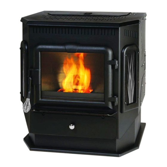
INSTALLATION & OPERATION MANUAL
MODEL NUMBERS:
Thank you for purchasing this product from a fine line of heating equipment.
We wish you many years of safe heating pleasure with your new heating appliance.
IMPORTANT: IF YOU HAVE A PROBLEM WITH THIS UNIT DO NOT RETURN IT TO
These freestanding Pellet/Corn/Multi-fuel units are approved for mobile home or doublewide
installation with outside combustion air hook-up. See "Flue System" section of manual.
Mobile home installation should be in accordance with the Manufactured Home and Safety
CAUTION: The structural integrity of the mobile home floor, wall and ceiling/roof
NOTE: WE DO NOT RECOMMEND PELLET/CORN/MULTI-FUEL STOVES AS YOUR ONLY SOURCE OF HEAT.
England's Stove Works highly recommends the use of smoke detectors and
Carbon Monoxide detectors with any hearth product, including this unit. Follow all
manufacturers' instructions when using smoke or Carbon Monoxide detectors.
CAUTION: Please read this entire manual before installation and use of this
WARNING: USE OF OUTSIDE AIR IS MANDATORY WITH THIS UNIT.
DO NOT OPERATE UNIT WITH HOPPER OPEN. LID MUST BE SHUT AND TIGHTLY SECURED.
FAILURE TO FOLLOW THESE INSTRUCTIONS COULD RESULT IN PROPERTY DAMAGE,
BODILY INJURY OR EVEN DEATH. FOR YOUR SAFETY AND PROTECTION, FOLLOW ALL THE
INSTALLATION INSTRUCTIONS. CONTACT YOUR LOCAL BUILDING OR FIRE OFFICIALS FOR
RESTRICTIONS AND INSTALLATION INSPECTION REQUIREMENTS (INCLUDING PERMITS) IN
YOUR AREA.
Save These Instructions.
THE DEALER. CONTACT TECHNICAL SUPPORT @ 1-800-245-6489.
Standard (HUD), CFR 3280, Part 24.
WARNING: Do Not Install in Sleeping Room.
Please Note the Following Precautionary Statements:
Pellet/Corn/Multi-fuel burning room heater.
Keep children, furniture, fixtures and all combustibles away from
any heating appliance.
DO NOT OPERATE WITH DOOR OPEN
Questions? Need Parts or Options?
10-CPM
49-TRCPM
Mobile Home Use:
must be maintained.
SAFETY NOTICE
www.heatredefined.com
49-SHCPM
Rev. 5/2015
Advertisement
Table of Contents

Summary of Contents for Englander 10-CPM
- Page 1 INSTALLATION & OPERATION MANUAL MODEL NUMBERS: 10-CPM 49-TRCPM 49-SHCPM Thank you for purchasing this product from a fine line of heating equipment. We wish you many years of safe heating pleasure with your new heating appliance. Save These Instructions. IMPORTANT: IF YOU HAVE A PROBLEM WITH THIS UNIT DO NOT RETURN IT TO THE DEALER.
- Page 2 A letter from our Technical Support department: Thank you for purchasing this fine product from England’s Stove Works! England's Stove Works was started, and is still owned by, a family that believes strongly in a "Do It Yourself" spirit – that’s one reason you found this product at your favorite “Do It Yourself”...
- Page 3 IMPORTANT INFORMATION Installation of this Pellet/Corn/Multi-fuel unit should be performed by a professional only. Check local installation codes for your area. Call your Homeowner’s Insurance representative for inspection of your stove’s installation. Read and comply with the instructions in this manual. This unit should be tested (dry run) for 20 minutes before loading pellets or cherry pits.
-
Page 4: Important Notice
Keep corn, pellets and all other combustible materials a safe distance from the unit. This unit will require floor protection if installed on a combustible surface. The minimum floor protector for this unit is 36” x 48” which should give you at least six inches (6”) of protection at the rear and at each side, and six inches (6”) minimum in the front of the unit. -
Page 5: Unit Preparation
UNIT PREPARATION Attach the spring handle to the door by turning it counterclockwise. Important: Also check hopper latch – must be tight so that the top is sealed to prevent back-burn. Test your 110-volt outlet for current and then plug in the unit. (Must be a 15A circuit minimum, should be 20A if circuit is GFIC protected. - Page 6 The Pellet/Corn/Multi-fuel stove is tested for operation with corn with 14% or less moisture content; it is recommended that corn with 11-12% moisture be used for most efficient operation of this unit. Corn with over 12% moisture has a lower BTU value and will be hard to burn on the lower settings.
-
Page 7: Vent Termination Clearances
VENT TERMINATION CLEARANCES A) MIN. 4-FT CLEARANCE BELOW OR BESIDE ANY DOOR OR WINDOW THAT OPENS. B) MIN. 1-FT CLEARANCE ABOVE ANY DOOR OR WINDOW THAT OPENS. C) MIN. 2-FT CLEARANCE FROM ANY ADJACENT BUILDING. D) MIN. 7-FT CLEARANCE FROM ANY GRADE WHEN ADJACENT TO PUBLIC WALKWAYS. - Page 8 NOTE: YOUR UNIT MUST BE INSTALLED BY A QUALIFIED INSTALLER, SUCH AS AN NFI CERTIFIED SPECIALIST GUIDELINES FOR EXHAUST VENTING SYSTEMS DESIGN INSTALL VENT AT CLEARANCES SPECIFIED BY THE VENT MANUFACTURER A UL listed three-inch or four-inch (3”or 4”) type “L” corn vent exhaust system must be used for installation and attached to the pipe connector provided on the back of the unit.
- Page 9 Total length of horizontal vent must not exceed 48” (4 ft.). Use three-inch (3”) U.L.- approved CORN VENT TWIST-LOCK PIPE when installing this stove and follow the manufacturer’s specifications for installation and clearances (we highly recommend Dura- Vent corn twist-lock pipe – our Part Number AC-33000). Even though this pipe interlocks, it is recommended to seal all connections with high temperature silicone (our Part Number AC-RTV3) or aluminum duct seal tape.
-
Page 10: Burning Solid Fuels
BURNING SOLID FUELS Ashes will need to be removed from the unit periodically. See Ash Removal section. You can minimize cleaning required and maximize efficiency by maintaining the proper draft. This unit has been designed to burn premium pellets, dry shelled corn or dried cherry pits that meet the Pellet Fuels Institute (PFI) standards. -
Page 11: Flue System
FLUE SYSTEM Caution: Follow the pipe manufacturer’s installation instructions and directions for passing through combustible walls and ceilings. Be sure to check local codes in your area. NOTE: See the installation drawing later in this manual (Illustration 1). This unit is equipped with a negative draft system that pulls combustion air through the burnpot and pushes the exhaust air out of the dwelling. - Page 12 The through-the-wall installation is the least expensive and simplest installation. In a through- the-wall installation you should be mindful of the snowdrift line, as well as dead grass and leaves. We recommend a three foot (3’) minimum vertical rise on the inside or the outside of the dwelling. Through the Ceiling When venting the stove through the ceiling, the pipe is connected the same as through the wall, except the clean out tee is always on the inside of the house, and a 3”...
-
Page 13: Floor And Wall Protection
Freestanding Pellet/Corn/Multi-fuel Installation Caution: Follow the pipe manufacturer’s installation instructions and directions for passing through combustible walls and ceilings. Check local codes in your area. Illustration 1 Our Part AC-33000 is acceptable for through-the-wall Must have installation. minimum 3” (We recommend 4” adapter before tee for 2500+ ft. -
Page 14: Start-Up Procedures
OPERATING INSTRUCTIONS CAUTION: DO NOT OPERATE WITH THE DOOR OPEN. Do not burn trash (paper bags, etc.) in this unit. This stove has an induced draft system and is designed to operate continuously, as frequent shutdown is not required. The setting of the “Heat Range” touch pad will control the heat output and the amount of fuel the unit will burn (see “Control Board”... - Page 15 WARNING! For pellets and corn, when the “Air On” button on the bottom of the Control Board is pressed, you must make sure you see the number “1“ in the Blower Speed window. The Stirrer must be running in the pellet and corn modes (mode 1 – pellet; mode 5 – corn, see Fuel Change Procedure, page 16). (As previously stated, the Stirrer will stop if you press the “Air On”...
- Page 16 NOTE If the unit does not start or maintain a fire, you will receive an E-2 in the Heat Range and Blower Speed window of the Control Board. If this occurs, wait until unit has cooled completely down and repeat. Locking Collar Hitch Pin...
- Page 17 FUEL CHANGE PROCEDURE When starting the stove with corn, push the “AIR ON TEMP” button and hold, which will rotate the Stirrer mechanism in the burnpot. Release the button when the 4-prong side of the Stirrer is straight up (in the “12:00” position, as shown in Illustration 2, page 13). Then follow the previous instructions concerning placing the handful of pellets in the burnpot and starting your fire (Manually Starting Your Unit, page 14).
-
Page 18: Operational Notes
E-Codes “E-Codes,” or Error Codes, are codes that will appear in the Heat Range and Blower Speed windows of the Control Board if your unit experiences problems. If you receive these codes, wait until the unit is cooled completely down before trying to restart your unit. If the unit continues to display any E-Code(s), please contact Technical Support at (800) 245-6489 before further attempting to restart your unit. -
Page 19: Shutdown Procedure
SHUT-DOWN PROCEDURE WARNING: NEVER SHUT DOWN THIS UNIT BY UNPLUGGING IT FROM THE POWER SOURCE. Refer to the following instructions: Press the “OFF” touch pad to put the stove in the “Shut-Down” mode. There will be an “S D” in the Heat Range and Blower Speed windows while the unit is shutting down to verify this. -
Page 20: Daily Operation
DAILY OPERATION Refueling the Unit Always press the “OFF” touch pad before refueling. The hopper on this stove holds approximately 50-lbs. (wood pellets), and should be refilled when the fuel level drops to three or four inches. Note: The hopper lid will be warm; therefore, you should always use some type of hand protection. NEVER place your hand near the auger while the stove is operating. -
Page 21: Ash Removal And Disposal
As with any maintenance concerning this unit, be sure the unit is “OFF” and has completed the Shut- Down cycle BEFORE beginning. Be aware that metal parts in the firebox can remain HOT long after the fire has gone out and EVEN after the Shut-Down cycle is complete. Always use extreme caution when handling potentially hot stove parts, even if you think they should be cold. -
Page 22: Maintenance
Soot and Fly ash: Formation and Need for Removal – The products of combustion will contain small particles of fly ash. The fly ash will collect in the exhaust venting system and restrict the flow of flue gases. Incomplete combustion, such as occurs during startup, shutdown, or incorrect operation of the room heater will lead to some soot formation which will collect in the exhaust venting system. - Page 23 As with any maintenance concerning this unit, be sure the unit is “OFF” and has completed the Shut- Down cycle BEFORE beginning. Be aware that metal parts in the firebox can remain HOT long after the fire has gone out and EVEN after the Shut-Down cycle is complete. Always use extreme caution when handling potentially hot stove parts, even if you think they should be cold.
- Page 24 Gaskets IMPORTANT: IMPROPER GASKET MAINTENANCE, INCLUDING FAILURE TO REPLACE GASKETS, CAN CAUSE AIR LEAKS RESULTING IN SMOKE-BACKS. This unit comes with a ” rope gasket around the door that should be replaced annually. To replace the door gasket (Part # AC-DGKCPM), the old gasket must first be removed entirely — prior to adding the new adhesive, you may have to scrape the old cement from the door channel.
- Page 25 Control Board The Control Board (Part # CPM-CB07) is a digital read-out board. This board offers a wide variety of settings to operate the unit. This part can be removed from the unit by loosening the two outside screws and pulling the board back to the inside of the stove. The rear access panel should be removed prior to removing the control board.
-
Page 26: Circuit Board Functions
Illustration 7 Control Board Diagram (Wiring) CIRCUIT BOARD FUNCTIONS COMPONENT OPERATION START OPERATION END Exhaust Blower Starts Immediately. Will continue until shutdown. Shutdown will (Combustion) occur when the operating temperature is below 90 degrees. Stirrer Three minutes after starting, the Stirrer Will continue intermittently, as determined by the will begin to turn. -
Page 27: Accessory Items
ACCESSORY ITEMS The following accessories can be added to your unit at anytime after purchase; however, let the unit cool down before adding any accessories. Thermostat An external thermostat (such as our Part # PU‐DTSTAT (wall) or Part # AC‐3003 (remote)) can be used on our Pellet/Corn/Multi‐fuel units as long as it is a low‐voltage that works with millivolt systems. After unplugging ... -
Page 28: Replacement Parts
REPLACEMENT PARTS ITEM PART NUMBER PART DESCRIPTION CA-10 Door AC-G20 Glass with Gasket H 11.5 X W 14.75 AC-GGK Glass Gasket Kit AC-GSCPM Glass Supports CA-11 Side Panel Castings CA-DH Cast Door Handle CPM-CFB Brick Fiber board CPM-BP Burnpot CPM-FS Fuel Stirrer CPM-MC Fuel Stirrer Collar... - Page 29 Pellet/Corn/Multi-fuel Stove Exploded View Diagram Illustration 8 Dimensions of your corn/pellet/multi fuel unit: ”W x 30 ”H x 31 “D 391 lbs. (Approx.18” height from floor to center of exhaust) CAUTION: UNPLUG THE UNIT PRIOR TO ANY SERVICE WORK! IMPORTANT! READ AND FOLLOW ALL INSTALLATION AND MAINTENANCE INSTRUCTIONS, INCLUDING CLEANING THE UNIT AS SPECIFIED, AND REPLACING GASKETS ANNUALLY, AND PARTS AS NEEDED.
- Page 30 Adjusting your Hopper Lid Latch The seals around the top of the pellet hopper are important to safe and efficient operation of the unit. The latch installed on these units is designed to pull the hopper lid tight against this seal. Over the course of operation as these seals “wear in”...
-
Page 31: Troubleshooting Guide
TROUBLE-SHOOTING GUIDE WARNING: TO AVOID ELECTRICAL SHOCK ALWAYS DISCONNECT THE UNIT FROM THE POWER SOURCE BEFORE ATTEMPTING ANY REPAIR. IF THIS GUIDE DOES NOT CORRECT THE PROBLEM CALL YOUR LOCAL DEALER OR OUR TECHNICAL SUPPORT AT 1-800-245-6489. Problem Cause Solution Auger not turning Loose set screw Tighten setscrew on collar... - Page 32 TROUBLE-SHOOTING GUIDE WARNING: TO AVOID ELECTRICAL SHOCK ALWAYS DISCONNECT THE UNIT FROM THE POWER SOURCE BEFORE ATTEMPTING ANY REPAIR. IF THIS GUIDE DOES NOT CORRECT THE PROBLEM CALL YOUR LOCAL DEALER OR OUR TECHNICAL SUPPORT AT 1-800-245-6489. Problem Cause Solution 10.
- Page 33 You may write your unit’s Manufacture Date and Serial Number in the blank spaces on this sample tag, for future reference. This sample tag also shows the safety info. such as UL testing standard, etc. for your local officials, or anyone else who may need reference information. IMPORTANT! READ AND FOLLOW ALL INSTALLATION AND MAINTENANCE INSTRUCTIONS, INCLUDING CLEANING THE UNIT AS SPECIFIED, AND REPLACING GASKETS ANNUALLY, AND PARTS AS NEEDED.
- Page 34 Have this information on hand if you phone the factory or your dealer regarding this product. Retain for your files: Model Number __________________________ Date of Purchase ________________________ Date of Manufacture _________________ Serial #_____________________ LIMITED 5 YEAR WARRANTY FROM THE DATE OF PURCHASE TO THE ORIGINAL OWNER The manufacturer extends the following warranties: Five Year Period: 1.
- Page 35 WARRANTY REGISTRATION for England’s Stove Works Purchased by (Name) ______________________________________________ Address _________________________________________________________ City ________________________ State __________ Zip _________________ Telephone _______________________________________________________ Email Address ___________________________________________________ DEALER INFORMATION Purchased From (Dealer) ___________________________________________ Address _________________________________________________________ City ________________________ State __________ Zip _________________ UNIT INFORMATION (Please be sure to refer to label on stove or sale receipt to complete this section) Model Number _______________________ Purchase Date ________________________ Purchase Price _______________________...
- Page 36 IMPORTANT! READ AND FOLLOW ALL INSTALLATION AND MAINTENANCE INSTRUCTIONS, INCLUDING CLEANING THE UNIT AS SPECIFIED, AND REPLACING GASKETS ANNUALLY, AND PARTS AS NEEDED. ENGLAND’S STOVE WORKS IS NOT RESPONSIBLE FOR ANY DAMAGE OR INJURY INCURRED DUE TO NEGLECT, OR DUE TO UNSAFE INSTALLATION OR USAGE OF THIS PRODUCT.
- Page 37 PELLET - Meets the 2015 U.S. Environmental Protection Agency’s wood emission limits for wood heaters sold after May 15, 2015 PLEASE NOTE: EPA INFORMATION The following additions to your owner’s manual will enable you to achieve optimal emissions performance from your stove. Important safety tips are also included. ‐ Proper Installation – Please refer to the Installation section of your owner’s manual and follow the guidelines listed therein for safety and for optimal emissions performance. Additional information: Venting: Be sure to follow your owner’s manual’s recommendation for venting, including the proper types of flue systems and pellet vent pipe. Also note that Outside Air Connection (combustion air) is MANDATORY for proper safe operation, and to achieve optimal emissions performance. Observe the vent termination clearances specified in your owner’s manual, and contact our Technical Support if you have any questions. Phone (800) 245‐6489 or email service@englanderstoves.com . Be certain that all aspects of the venting system are installed to the venting manufacturer’s instructions, particularly the required clearances to combustibles. Your pellet stove operates on a negative draft system, which pulls combustion air through the burn pot and pushes the exhaust air through the vent pipe and out of the building. This unit must be installed in accordance with your owner’s manual’s detailed descriptions of venting techniques; not installing the stove in accordance with the details listed can result in poor stove performance (including poor emissions), property damage, bodily injury or death. England’s Stove Works is not responsible for any damage incurred due to a poor or unsafe installation. IMPORTANT! READ AND FOLLOW ALL INSTALLATION AND MAINTENANCE INSTRUCTIONS, INCLUDING CLEANING THE UNIT AS SPECIFIED, AND REPLACING GASKETS ANNUALLY, AND PARTS AS NEEDED.
- Page 38 Additional Venting Information Do not mix and match components from different pipe manufacturers when assembling your venting system (i.e. Do NOT use venting pipe from one manufacturer and a thimble from another). We require a minimum vertical rise of 36 in. (3 ft.) of pipe to create natural draft in the system, which helps evacuate smoke from the stove in the event of a power failure or combustion blower failure. Venting systems 15.0 ft. or shorter may be composed entirely of 3.0 in. pellet pipe; to reduce frictional losses, venting systems longer than 15.0 ft. should be composed of 4.0 in. pellet pipe. Do not terminate the venting system directly beneath any combustible structure such as a porch or deck. Follow NFPA 211 rules listed below for venting system termination location relative to windows and other openings in the dwelling. o NFPA 211 (2006 ed.) Section 10.4 Termination: 10.4.5 (1) The exit terminal of a mechanical draft system other than direct vent appliances (sealed combustion system appliances) shall be located in accordance with the following: (a) Not less than 3 ft. (.91 m) above any forced air inlet located within 10 ft. (3.0m). (b) Not less than 4 ft. (1.2 m) below, 4 ft. (1.2 m) horizontally from or 1 ft. (305 mm) above any door, window or gravity air inlet into any building. (c) Not less than 2 ft. (0.61 m) from an adjacent building and not less than 7 ft. (2.1 m) above grade when located adjacent to public walkways. Distance between the termination opening and grade should be a minimum of 2 ft. (24 in.) contingent on the grade surface below the termination. When determining the termination height above grade, consider snow drift lines and combustibles such as grass or leaf accumulation. In areas where significant snowfall is possible, the termination height must be sufficiently high to keep the termination free of snow accumulation. ...
-
Page 39: Outside Air Hook-Up
OUTSIDE AIR HOOK‐UP The use of outside combustion air is mandatory on this pellet stove. The outside air connection pipe protrudes from the lower rear center of the stove; use the included outside air kit to attach your stove to outside combustion air. Instructions and all the parts needed to make the outside air connection to your pellet stove are included with the outside air kit. If it is not feasible to use the included outside air hookup kit in your stove installation, other materials may be used, provided the following rules are followed: The pipe used for outside air hookup must be metal, with a minimum thickness of .0209 in. (25 gauge mild steel) or greater and an inside diameter of approximately 2.0 in. All pipe joints and connections should be sealed with pipe clamps or other mechanical means, to insure a leak free outside air connection. Long runs of pipe and excessive elbows for outside air should be avoided. Due to frictional resistance in pipe, any excessive outside air piping can result in poor stove performance. A screen or other protection device must be fitted over the outside air termination point to prevent rain, debris and nuisance animals from entering the piping system. Increase the outside air pipe size to 3.0 in. diameter pipe if the outside air connection is more than 6 ft. in length, more than two (2) elbows are used or if the stove is installed in a basement. The outside air connection system should be inspected at least annually to be certain it is free from blockage. ‐ Operation and Maintenance – Please refer to the ‘Operation’ (Operating Instructions) and Maintenance (including Ash Removal/Disposal) sections of your owner’s manual and follow the guidelines listed therein for safety and for optimal emissions performance. Additional Information: Following the instructions in your owner’s manual for Start‐Up (lighting a fire) will ensure a proper fire, as well as helping minimize visible emissions. ... - Page 40 Daily Operation Notes Only high quality, ¼” (.25 in.) diameter wood pellets, should be used in this stove. Using low grade wood pellets with high ash content OR wood pellets with a high moisture content can cause the burn pot to fill with ash at a more rapid pace and can cause intervals between periodic maintenance to become significantly shorter. Please read the “Maintenance” section of this manual thoroughly to understand how fuel selection affects stove operation, maintenance and cleaning. Variation in the flame height is normal; not all wood pellet fuel is uniform in size, which can affect the way pellets are fed into the burn pot. Although the flame height may increase and decrease during operation, there is no loss of efficiency. Always store wood pellet fuel in a dry location; storing wood pellet fuel in a dry location ensures the fuel will remain pelletized and low in moisture content. Also, be certain that all wood pellet fuel is stored at a safe distance from the pellet heater; storing fuel in close proximity to the stove can result in a fire. This pellet burning room heater is equipped with a specially designed burn pot which comes preinstalled from the factory. This burn pot elevates the burning pellets and delivers air at the precisely‐required locations. Pellets must only be burned in the factory burn pot; no modifications should be made to this burn pot and no additional grates or other fire elevators should be used. ‐ WHAT FUELS NOT TO USE: CAUTION NEVER USE GASOLINE, GASOLINE‐TYPE LANTERN FUEL, KEROSENE, CHARCOAL LIGHTER FLUID, OR SIMILAR LIQUIDS TO START OR “FRESHEN UP” A FIRE IN THIS HEATER. KEEP ALL SUCH LIQUIDS WELL AWAY FROM THE HEATER WHILE IN USE. ADDITIONALLY, NEVER APPLY FIRE‐STARTER TO ANY HOT SURFACE OR EMBERS IN THE STOVE. DO NOT USE CHEMICALS OR FLUIDS TO START THE FIRE. DO NOT BURN FLAMMABLE FLUIDS SUCH AS GASOLINE, NAPHTHA OR ENGINE OIL. DO NOT BURN GARBAGE; LAWN CLIPPINGS OR YARD WASTE; MATERIALS CONTAINING RUBBER, INCLUDING TIRES; MATERIALS CONTAINING PLASTIC; WASTE PETROLEUM PRODUCTS, PAINT OR PAINT THINNERS, OR ASPHALT PRODUCTS; MATERIALS CONTAINING ASBESTOS; CONSTRUCTION OR DEMOLITION DEBRIS; RAILROAD TIES OR PRESSURE‐ TREATED WOOD; MANURE OR ANIMAL REMAINS; SALT WATER DRIFTWOOD OR OTHER PREVIOUSLY SALT WATER SATURATED MATERIALS; UNSEASONED WOOD; PAPER PRODUCTS, CARDBOARD, PLYWOOD OR PARTICLEBOARD. THE PROHIBITION AGAINST ...
- Page 41 ‐ Air Controls: Your pellet stove is equipped with a control board that automatically adjusts the air to fuel ratio for optimum emissions. See your owner’s manual for information on operating the control board, and for other operational information on achieving the best burn, including these tips: The control board on this stove allows the user to adjust the heat output and convection blower speed, and turn the unit on and off. The lower buttons on the control board (Low Fuel Feed, Low Burn Air, and Air on Temp) are not meant to be adjusted during normal operation of the unit. These buttons are factory preset and should not be adjusted by the user. To energize the unit and initiate a fire, press the “On” button. The LED above the button should turn green and the control board should display “S U” shortly after pressing the button. To shut the unit down, press the “Off” button. The LED above the button should turn red and the board should display “S d” shortly after pressing the button. This initiates the shut down sequence, and the stove will remain in shut down mode until it has cooled down. To increase the heat output of the stove, press the “Up” heat range button. The number in the heat range display window will increase, signifying that the control board is now adjusting the heat output to your desired level. The blower speed will increase the same amount as the heat range, because the stove is designed to operate with the blower speed greater than or equal to the heat range. Pressing the “Down” arrow will decrease the heat range and blower speed. To increase the blower speed without increasing the heat range, press the Blower Speed “Up” arrow until the desired blower speed is shown in the display window. Pressing the “Down” arrow will decrease the blower speed; however, the control board will not allow the blower speed to be set lower than the heat range Caution This unit is meant to operate only with the ash pan and main viewing door closed. Smoke spillage and an inefficient, lazy burn will result from attempting to operate the stove with either door open. In addition, using fuel other than wood pellets can create an unsafe situation and can also generate excess carbon monoxide. Carbon monoxide is an odorless, colorless gas which can be deadly. Be sure to burn only wood pellets. The use of a carbon monoxide detector is strongly recommended. ...
- Page 42 ‐ ASH REMOVAL – Follow your Owner’s manual’s instructions regarding removal and disposal of ashes. Also be sure to follow ALL Maintenance requirements as listed. ‐ REPLACEMENT of parts that are critical to emissions performance – Follow your Owner’s manual’s instructions regarding replacement of gaskets and other parts that are critical to emissions performance. Remember: “This wood heater needs periodic inspection and repair for proper operation. It is against federal regulations to operate this wood heater in a manner inconsistent with operating instructions in this manual.” ‐ Smoke Detectors England’s Stove Works, Inc. highly recommends the use of smoke detectors in every room of the house. However, locating a smoke detector directly above this unit can result in nuisance alarms. ‐ Compliance: “This non‐catalytic wood heater meets the 2015 U.S. Environmental Protection Agency’s wood emission limits for wood heaters sold after May 15, 2015.” ‐ Tamper Warning: “This wood heater has a manufacturer‐set minimum low burn rate that must not be altered. It is against federal regulations to alter this setting or otherwise operate this wood heater in a manner inconsistent with operating instructions in this manual.” ‐ Warranty: See your Owner’s manual for a Warranty Registration instruction page, as well as instructions for warranty procedures. For parts, warranty replacement procedures may be found at our parts store site: www.store.heatredefined.com IMPORTANT! READ AND FOLLOW ALL INSTALLATION AND MAINTENANCE INSTRUCTIONS, INCLUDING CLEANING THE UNIT AS SPECIFIED, AND REPLACING GASKETS ANNUALLY, AND PARTS AS NEEDED.
Need help?
Do you have a question about the 10-CPM and is the answer not in the manual?
Questions and answers