Haier AW07LC2VHA Technical Overview
Hide thumbs
Also See for AW07LC2VHA:
- Installation manual (30 pages) ,
- User manual (8 pages) ,
- User manual (8 pages)
Table of Contents
Advertisement
Multi-Zone Technical Overview
Table of Contents
Introduction ..................................................................................................................................... 2-11
Nomenclature ....................................................................................................................................................... 2
Specifications .....................................................................................................................................................3-5
Safety Overview .................................................................................................................................................6-7
Functions & Controls....................................................................................................................................... 8-11
Outdoor Unit Technical Overview ................................................................................................... 12-33
Components ................................................................................................................................................. 12-18
Operations .................................................................................................................................................... 19-25
Testing ........................................................................................................................................................... 26-28
Error Codes ................................................................................................................................................... 29-33
Indoor Unit Technical Overview - Wall Mount .................................................................................. 34-43
Components ................................................................................................................................................. 34-39
Testing ........................................................................................................................................................... 40-41
Error Codes ................................................................................................................................................... 42-43
Indoor Unit Technical Overview - Cassette ..................................................................................... 44-51
Components ................................................................................................................................................. 44-47
Testing ........................................................................................................................................................... 48-51
Indoor Unit Technical Overview - Slim Duct .................................................................................... 52-57
Components ................................................................................................................................................. 52-55
Testing ........................................................................................................................................................... 56-57
Wired Controller ............................................................................................................................ 58-64
Wireless Remote Controller ........................................................................................................... 65-68
References......................................................................................................................................69-121
Troubleshooting,Resistance Values, Error Detection, Piping Length Limits ............................................ 69-72
Component Ratings ............................................................................................................................................ 73
Ductwork Installation ......................................................................................................................................... 74
Wiring ............................................................................................................................................................. 75-89
Piping Installation Dimensions ..................................................................................................................... 90-95
Flow Charts.................................................................................................................................................. 96-109
Sensors ...................................................................................................................................................... 101-121
TECHNICAL OVERVIEW
PAGE 1
Advertisement
Table of Contents

Related Manuals for Haier AW07LC2VHA


Summary of Contents for Haier AW07LC2VHA
-
Page 1: Table Of Contents
Multi-Zone Technical Overview Table of Contents Introduction ............................. 2-11 Nomenclature ............................... 2 Specifications ..............................3-5 Safety Overview ..............................6-7 Functions & Controls............................8-11 Outdoor Unit Technical Overview ....................12-33 Components ..............................12-18 Operations ..............................19-25 Testing ................................26-28 Error Codes ..............................29-33 Indoor Unit Technical Overview - Wall Mount .................. -
Page 2: Introduction
NOMENCLATURE - Model Name Explanation Nomenclature 1 U 18 ES 2 V H A 1 U 18 LC 2 V H A Unit Type A = Indoor Unit Product Revision 1 = Single Zone Outdoor 2 = Two Zone Outdoor 3 = Three Zone Outdoor 4 = Four Zone Outdoor System Type... -
Page 3: Specifications
SPECIFICATIONS Multi-Zone Indoor INTRODUCTION PAGE 3... - Page 4 SPECIFICATIONS Multi-Zone Indoor INTRODUCTION PAGE 4...
- Page 5 SPECIFICATIONS Multi-Zone Outdoor INTRODUCTION PAGE 5...
-
Page 6: Safety Overview
SAFETY OVERVIEW Read These Safety Precautions Be sure to read the safety precautions before conducting work. The items are classified into “Warning” and “Caution.” The “Warning items are especially important since they can lead to death or serious injury if not followed closely. The “Caution” items can also lead to serious accidents under some conditions if they are not followed. - Page 7 SAFETY OVERVIEW Read These Safety Precautions Be sure to use the specified cable to connect between the indoor and outdoor units. Make the Replace power cables and lead wires if they are connections securely and route the cable properly scratched or deteriorated. Damaged cable and so that there is no force pulling the cable at the wires can cause electrical shock, excessive heat connection terminals.
-
Page 8: Functions & Controls
OVERVIEW & INTRODUCTION Functions and Controls Auto Mode Dry Mode (Dehumidifying mode) When the running mode is turned to auto after starting the temperature control range: 60---86°F system, the system will first determine the running mode temperature difference: ±2°F according to the current room temperature and then will Control feature: Send the dehumidifying signal to the outdoor run according to the determined mode: Tr means room system. - Page 9 OVERVIEW & INTRODUCTION Functions and Controls Heat Mode mode. During the cold air proof operation, the indoor system will continuously send ‘indoor high speed’ signals to the temperature control range: 60---86°F outdoor system. temperature difference: ±2°F Residue heat sending. The indoor fan will send the Control feature: the temperature compensation is residue heat at a low speed for 12 seconds.
- Page 10 OVERVIEW & INTRODUCTION Indoor Unit Operating Mode Conflicts Indoor System Mode Conflict Low Load Protection Control The indoor unit is trying to operate in a mode that is opposite In order to prevent the frosting of the indoor heat interaction of the mode the outdoor unit is currently operating in.
- Page 11 OVERVIEW & INTRODUCTION Multi-Zone Outdoor Multi-Zone Outdoor When the compressor first starts The Control of the Outdoor Unit Expansion Valve The compresor will start in low frequency. After a brief time When unit starts, the EEV valves will energize and change to a delay, the compressor will come up to operating speed to standard opening.
-
Page 12: Outdoor Unit Technical Overview
Outdoor Unit Technical Overview Introduction - Overview Outdoor Unit Technical Overview The outdoor unit features a variable speed rotary type com- pressor that delivers refrigerant flow to up to 4 individual indoor units. The system uses R-410A refrigerant mixed with PVE oil. - Page 13 TECHNICAL OVERVIEW Electronic Control Unit Circuit Board (ECU) Electronic Control Unit Circuit Board (ECU) The Electronic Control Unit operates the outdoor fan motor, crankcase heater, EEV stepper motors and the 4-way valve. This board also controls the general operation of the system and makes all of the diagnostic decisions.
- Page 14 OUTDOOR UNIT TECHNICAL OVERVIEW Technical - Overview Module Circuit Board (MCB) Module Circuit Board (MCB) The MCB generates heat that is transferred to a heat sink located on the back of the board. The heat sink trans- The Module Circuit Board generates 3 phase DC power mits this heat to the outdoor air.
- Page 15 OUTDOOR UNIT TECHNICAL OVERVIEW Technical Overview Power Circuit Board (PCB) Power Circuit Board (PCB) The voltage that powers the indoor units connects to terminals P3 and P4. The Electronic Control Unit The purpose of the Power Circuit Board is to filter out poten- receives power to operate via connections at terminals P5 tial electrical noise before it reaches the outdoor unit elec- and P6.
-
Page 16: Components
OUTDOOR UNIT TECHNICAL OVERVIEW Outdoor Unit Components 4 Way Valve Outdoor Fan Motor 4 Way Valve Outdoor Fan Motor The 4 Way Valve is energized during heating mode operation. The Outdoor Fan Motor is a variable speed motor. The motor The valve is energized with 230 volts via a connection plug on is energized via a connection plug on the ECU. - Page 17 OUTDOOR UNIT TECHNICAL OVERVIEW Outdoor Unit Components When a call for cooling or heating occurs, the EEV will be po- sitioned to a starting position. The starting position is based upon the Outdoor Ambient Air Temperature. For example, in cooling mode, at outdoor air temperature above 68°F, the starting position of the valve will be 250 pulses.
- Page 18 OUTDOOR UNIT TECHNICAL OVERVIEW Outdoor Unit Components Temperature Sensors Outdoor Unit The outdoor unit has two groups of temperature sensors. The first group of sensors are Liquid and Gas Sensors that are asso- ciated with each indoor unit EEV. These sensors monitor the leaving liquid temperature from the EEV and the returning Suction Vapor temperature from the indoor units.
-
Page 19: Operations
OUTDOOR UNIT SEQUENCE OF OPERATION The outdoor unit is capable of controlling up to 4 individual indoor units. The outdoor unit will vary compressor capacity and outdoor fan motor speed to match the demand requirement from the indoor units. All capacity and diagnostic decisions are con- trolled by the outdoor unit ECU. - Page 20 OUTDOOR UNIT SEQUENCE OF OPERATION Cooling Mode Sequence of Operation valve. The 4 way valve will direct the hot gas to the outdoor coil. The refrigerant will condense in the outdoor coil and be The vapor refrigerant will then enter the 4 way valve and be slightly subcooled.
- Page 21 OUTDOOR UNIT SEQUENCE OF OPERATION Heating Mode Sequence of Operation Low pressure Suction temp. switch 4-way valve coil: sensor Comp- Refrigerant flow in cooling ressor Refrigerant flow in heating Discharge temp. sensor Accumulator separator Capillary tube Unit A gas pipe temp. sensor Indoor unit A High pressure switch...
- Page 22 OUTDOOR UNIT SEQUENCE OF OPERATION Heating Mode Sequence of Operation is monitored by the Suction Temperature Sensor. If abnormal temperature either hot or cool is detected, the frequency of the The indoor heat exchanger temperature sensor will monitor compressor may be adjusted or the system may stop operation the temperature of the indoor coil to ensure it is hot enough to to protect the compressor.
- Page 23 OUTDOOR UNIT TEMPERATURE SENSOR RESPONSES Outdoor Unit Control Information 10.2.1 Outdoor frequency control 10.2.4 Crankcase Heater Control A. The compressor running frequency is range is 20-95 RPS. The crankcase heater is controlled by the ECU. The heater 10.2.2 Electronic expansion valve (EEV) control keeps the compressor oil warm to prevent liquid refrigerant from migrating to the oil during periods where the system is A: EEV SPECIFICATION: Maximum open angle is 500 pulses.
- Page 24 OUTDOOR UNIT TEMPERATURE SENSOR RESPONSES Forced Defrost Operation 10.2.6 Forced Defrost Operation 10.2.8 Frequency Control when there is CT Over-current Protection 10.2.8. The system can be placed into a forced defrost cycle from the Stop immediately, if abnormal stop 3 times in 1 hour, the wired controller.
- Page 25 OUTDOOR UNIT TEMPERATURE SENSOR RESPONSES 10A, the frequency of the compressor decreases at the speed Forced Defrost Operation of 0.1HZ/second. There are times when the switch is not active. The periods of During compressor start-up, if the AC current is greater inactive switch operation are: than 9A, the frequency of the compressor increases at the prohibited speed.
-
Page 26: Testing
OUTDOOR UNIT TESTING PROCEDURES EEV testing Compressor Testing The EEV metering devices are stepper type valves that have up to 500 potential positional changes. The electrical coil that If the compressor fails to start, the compressor may have an is installed on the end of the EEV body rotates a magnetic internal electrical failure, the compressor may be seized me- field that opens and closes the valve. - Page 27 OUTDOOR UNIT TESTING PROCEDURES Outdoor Fan Motor Testing If the outdoor unit fan motor does not run or the Service Monitor board indicates an error code of 09, check the following voltages at connector CN11 on the outdoor unit ECU board. Set the meter to read DC volts with a minimum voltage range of 350 volts.
- Page 28 OUTDOOR UNIT TESTING PROCEDURES Temperature sensor testing Restricted/Sticking Outdoor Unit Check Valve Test The temperature sensors are negative coefficient type. These The Check Valve allows refrigerant to flow freely around the sensors will reduce their electrical resistance as temperature outdoor unit heat mode EEV during cooling mode. The valve is decreases.
-
Page 29: Testing
OUTDOOR UNIT ERROR CODES The Reference Section of this manual contains temperature Outdoor Unit Error Codes resistance tables that can be used to check the calibration of the sensors. The measured resistance must be within the If the ECU generates a system ERROR CODE, the code will be tolerances printed on the top of the tables. - Page 30 OUTDOOR UNIT ERROR CODES Pressure Switch Error Codes Outdoor Unit Pressure Switch Error Codes There are two pressure switches in the outdoor unit, a low pressure switch and a high pressure switch. They connect to the ECU via plugs CN-12 and CN-13. The low pressure switch is connected at CN-12 and the high pressure switch at CN-13. A low pressure error will generate an Error Code 44.
- Page 31 OUTDOOR UNIT ERROR CODES Indoor Unit and Outdoor Unit Communication Errors Error Code 15 This error indicates the indoor unit and outdoor unit are having a problem communicating information. The wiring path for the data signal is between Terminals 3 to 1 on the Terminal Blocks connecting the indoor unit to the outdoor unit. If the path is correct, the GREEN LED on the Service Monitor Board should be lit.
-
Page 32: Error Codes
OUTDOOR UNIT ERROR CODES Error Codes Related to the MODULE Board Operation Error Codes Related To The MODULE Board Operation Error Code 2 The module board detected excessive instantaneous current compressor , IPM hardware automatically stopped the Module Board output to protect the compressor. Potential causes include: •... - Page 33 OUTDOOR UNIT ERROR CODES Error Codes Related to MODULE Board Operation Error Code 26 Possible Causes: CPU module reset indicates possible drive module power • overcharge anomalies. Usually when the low line voltage conditions are • dirty outdoor coil present. Check for line voltage problems. •...
-
Page 34: Indoor Unit Technical Overview - Cassette
Indoor Unit Technical Overview INDOOR UNIT TECHNICAL OVERVIEW Indoor Wall Mount Unit Components Return Air Temperature Sensor Pipe Sensor Evaporator Coil Control Board Display Terminal Block Motor Horizontal Louver Stepper Motor Vertical Louvers Stepper Motor The wall mounted units act as evaporator coils during cooling Unlike typical air handlers found in the US market, these mode and condenser coils during heating mode. -
Page 35: Emergency Run
INDOOR UNIT TECHNICAL OVERVIEW Indoor Wall Mount Unit Circuit Board The Indoor Unit Circuit Board communicates with the outdoor unit ECU via a connection at Terminal Block screw 3. The data pulse that sends the communi- Fan Motor cation information can be measured with a voltmeter placed to DCV range. - Page 36 INDOOR WALL MOUNT UNIT TECHNICAL OVERVIEW Temperature Sensors Blower Assembly The blower assembly consists of a plastic blower wheel that The Piping Temperature Sensor senses indoor coil is connected to a variable speed indoor blower motor. A set temperature in the cooling mode and in the heating mode. screw holds the blower wheel to the blower motor.
- Page 37 INDOOR WALL MOUNT UNIT TECHNICAL OVERVIEW Test Procedures Accessing components/removing cover Open the 3 caps that cover the screws located behind the bottom of the louver. These caps flip up. To access components for service, first disconnect power to the outdoor unit. This will de-energize the indoor unit.
- Page 38 INDOOR WALL MOUNT UNIT TECHNICAL OVERVIEW Indoor Fan Motor Voltage Check If the indoor fan motor does not run. Remove the front cover and access the circuit board connection CN-9. 310VDC Reset power and turn the remote control fan command to Fan On mode. Pins 1 - 3 Motor Test If the motor doesn’t run, check for 310VDC between Pins 1 and 3.
- Page 39 INDOOR WALL MOUNT UNIT TECHNICAL OVERVIEW Step 6. Step 9. Unplug the motor from the circuit board. Remove 6 screws that hold the motor bracket and evaporator coil. Step 10. Step 7. Lift and slide the motor away from the Lift the evaporator coil and remove the motor blower wheel.
- Page 40 INDOOR WALL MOUNT UNIT SECTION Testing Temperature Sensors and Louver Motors Testing Louver Motors Testing Temperature Sensors The easiest problems to solve will involve codes that are If the louver does related to potential failure of temperature sensors. Common not operate with problems may include loose connections, open electrically, command from the and out of calibration.
- Page 41 INDOOR WALL MOUNT UNIT SECTION Testing Communication Circuit Antifreezing Protection Antifreezing Protection Testing Communication Circuit Prevents freeze-up of the indoor coil If an Error E7 occurs, perform the following test to determine if the indoor control board is functioning properly to send data The indoor unit coil temperature sensor will shut off the to the outdoor unit.
- Page 42 INDOOR WALL MOUNT UNIT Indoor Unit Error Codes Indoor Unit Error Codes (HSU218VHG Only) • refrigeration circuit restriction • seized compressor The error codes that are displayed on the indoor units • Bad Module Board may vary from the outdoor unit codes. The information communicated by the error code will be the SAME for both Error Code F22 indoor and outdoor units even though the numbers may...
- Page 43 INDOOR WALL MOUNT UNIT Indoor Unit Error Codes Error Code F11 Error Code F4 Recycle power and restart the system. If the compressor This code indicates the temperature of the compressor initially starts but then stops, replace the MODULE board and hot gas is too high.
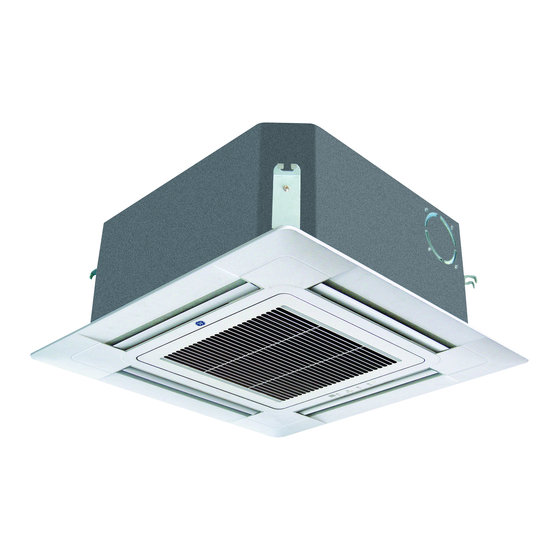
- Page 44 Cassette Unit Technical Overview Cassette Unit Components remote control and by commands from the outdoor unit ECU. Component Overview Refer to the Remote Control Information in the Reference section for louver control/remote procedures. The indoor cassette type units act as evaporator coils during cooling mode and condenser coils during heating mode.
- Page 45 CASSETTE UNIT TECHNICAL OVERVIEW Cassette Unit Indoor Circuit Board CN29 Louver Panel N Terminal CN1 Wired Remote L Terminal DIP Switches Communication Terminal CN14 Stepper Motor 3.15A 250V Fuse CN13 Sensors CN11 Fan Motor CN18 Float Switch CN9 Condensate Pump The indoor unit circuit board controls the switching functions display, check for line voltage at these connections.
- Page 46 CASSETTE UNIT TECHNICAL OVERVIEW Cassette Unit Components The Blower Assembly The Piping Temperature Sensor senses indoor coil temperature in the cooling mode and in the heating mode. The blower assembly consists of a plastic blower wheel that This sensor is used for Anti Freezing and Anti Cold Blow is connected to a PSC indoor blower motor.
- Page 47 CASSETTE UNIT TECHNICAL OVERVIEW Cassette Unit Components Accessing the blower motor and condensate pump Disconnect power to the outdoor unit. Remove the louver assembly. Condensate Tray Disconnect the main power wire to the indoor unit. Mounting Screw Unplug the condensate pump and float switch from wiring harness.
- Page 48 CASSETTE UNIT TECHNICAL OVERVIEW Cassette Unit Testing Procedures: Accessing Components/Removing Cover Indoor Fan Motor Test Procedure Indoor Motor If the indoor fan motor does not run. Disconnect power to the system. Remove the return air cover and access the circuit board connection CN-11. Reset power and turn the remote control fan command to Fan On mode.
- Page 49 CASSETTE UNIT TECHNICAL OVERVIEW Cassette Unit Sensor Testing Procedures Testing Temperature Sensors Temperature Sensor The easiest problems to solve will involve codes that are related to potential failure of temperature sensors. Common problems may include loose connections, open electrically, and out of calibration. Checking the condition of the sensors requires a temperature probe and an ohmmeter.
- Page 50 CASSETTE UNIT TECHNICAL OVERVIEW Cassette Unit Testing Procedures: Louver Motor Testing Louver Motors T ake electric box cover off If the louver does not operate with command from the remote control, either the indoor board is bad, or the louver motor is defective.
- Page 51 CASSETTE UNIT TECHNICAL OVERVIEW Cassette Unit Testing Procedures: Communication Circuit, Condensate Pump & Float Switch Testing Communication Circuit Check E7 If an Error E7 occurs, perform the following test to determine if the indoor control board is functioning properly to send data to the outdoor unit.
- Page 52 Slim Duct Unit Technical Overview Slim Duct The Slim Duct Indoor Unit will act as evaporator coils during cooling mode and condenser coils during heating mode. This unit can operate with a motorized supply air louver or it can have a LIMITED amount of ducting added to the unit’s return and supply air duct connection flanges.
- Page 53 SLIM DUCT OVERVIEW Slim Duct Components Layout of Components Drain Ports The layout of the system is very straightforward and The indoor unit has components are easily accessed should service be required. the option for either gravity drain systems • The circuit board is located under the electrical or the use of an control box cover.
- Page 54 SLIM DUCT TECHNICAL OVERVIEW Slim Duct Components Indoor Unit Circuit Board air temperature sensing functions. All operational decisions are controlled by the OUTDOOR UNIT ECU. The indoor unit circuit board controls the switching functions of the indoor unit. All control decisions are made by the The connections on the indoor board are shown here in the outdoor unit ECU.
- Page 55 SLIM DUCT TECHNICAL OVERVIEW Slim Duct Components SW1 DIP Switches Accessory Louver Motors The louver motors are stepper type motors that move the louvers up/down. The motors are controlled by pulsed voltage that cannot be measured. If the louver does not move when it should, check for a bind in the louvers.
-
Page 56: Testing
SLIM DUCT TESTING PROCEDURES Testing Temperature Sensors Procedure Test Condensate Pump and Associated Float Switch To test the electrical condition of a temperature sensor If the internal condensate pump does not operate, the pump perform the following: may be bad or the float switch may be defective. Perform the following test: Confirm the sensor is firmly attached to the circuit board connection plug. -
Page 57: Testing
SLIM DUCT TESTING PROCEDURES Testing Communication Circuit If an Error E7 occurs, perform the following test to determine if the indoor control board is functioning properly to send data to the outdoor unit. Perform this test with the unit powered and all wiring connected between indoor and outdoor unit. -
Page 58: Wired Controller
Wired Controller YR-E17 WIRED CONTROL PANEL FUNCTIONS Features and Interface Clock; Parameter setting/Inquiry; Malfunction display Timer ON/OFF; Sleep function; Parameter setting/Inquiry; Malfunction display ROOM/SET temp. and humidity display, each step is 0.5°C (1°F). For example, if the temp is 25°C (77°F), it will display 25.°C (77°F). Humidity display function is reserved. - Page 59 REMOTE CONTROLS WIRED CONTROLLER INSTALLATION Wired Controller Wiring Instructions Step By Step Guide To Slim Duct Unit Installation There are three methods to connect the wired controller to the indoor units. A. One wired controller controls one indoor unit; the indoor unit connects with the wired controller through a 3 conductor shielded cable.
- Page 60 WIRED CONTROLLER INSTALLATION Wired Controller Wiring Instructions Dimensions Unit: inch (mm) Dip Switch Dip Switch ON/OFF Function Default Setting Set as the slave controller SW1-1 Set as the master controller Ambient temp. display available SW1-2 Ambient temp. display unavailable Display ambient temp. from PCB of indoor SW1-3 Display ambient Temp.
- Page 61 WIRED CONTROLLER OPERATION Settings & Functions Switching between Fahrenheit & Celsius Initialization To switch from Celsius to Fahrenheit, select the mode you The wired controller will wish to operate (COOL, HEAT, DRY, INTELLIGENT/AUTO). momentarily display Press and hold the p key to reach 30 °C then continue holding all display icons upon the p key for 15 seconds until the display reads 86 °F.
- Page 62 WIRED CONTROLLER OPERATION Settings & Functions Timer Function Setting ECO Energy Saving Function NOTE: This function requires the ON/OFF key LED to be NOTE: The display backlight must be illumi- turned ON and the screen backlight to be illuminated. nated before proceeding. To turn the back- light on, press any key (MODE, FAN, pq, Press the SET key.
- Page 63 WIRED CONTROLLER OPERATION Settings & Functions Left/Right/Up/Down Swing Forced Cooling/Heating Note: This function requires the ON/OFF key LED to be The swing function deter- turned OFF and the screen backlight to be illuminated. mines air circulation. Forced Cooling 1. Press SET key to access When the system is turned off in cooling mode, press and hold Swing function circulation.
-
Page 64: Wired Controller
WIRED CONTROLLER OPERATION Settings & Functions Sleep Function Other Functions Note: These functions require the ON/OFF key LED to be NOTE: This function requires the ON/OFF key LED to be turned OFF and the screen backlight to be illuminated. turned ON and the screen backlight to be illuminated. Press the SET key. -
Page 65: Wireless Remote Controller
Wireless Remote Controller Note: TURBO/QUIET modes are only available when the unit is un- Functions der cooling or heating mode (not for auto or fan mode). Running the unit in QUIET mode for a long period of time may cause the room temperature to not reach the set temperature. - Page 66 WIRELESS REMOTE CONTROLLER OPERATION 4. Once the desired length of time is selected for the unit to Louver SWING Button - Vertical turn on, press the CONFIRM/CANCEL to confirm Air Flow Direction Adjustment this setting. Press the SWING UP/DOWN button to choose the position of the vertical airflow louvers.
- Page 67 WIRELESS REMOTE CONTROLLER OPERATION the time. After replacing batteries or a power failure occurs, function. the time setting will need to be reset. EXTRA FUNCTION Button According to the Time setting sequence of TIMER ON or Function: TIMER OFF, either Start-Stop or Stop-Start can be achieved. A) Refresh air - Feature not available on this series.
-
Page 68: Wireless Remote Controller
WIRELESS REMOTE CONTROLLER OPERATION G) Fahrenheit/Celsius mode shift on unit and remote - To switch between Fahrenheit and Celsius press the EXTRA FUNCTION button until either Celsius or Fahrenheit is displayed. Press the CONFIRM/CANCEL button to apply the change. H) 50°F low temperature heating - Feature not available on this series. -
Page 69: References
REFERENCES Troubleshooting Trouble shooting Outdoor Wired controller Cassette indoor display outdoor Wall mounted Outdoor unit fault possible reasons display(Hex)---for Timer lamp Running lamp indoor display display duct flash time flash time Faulty of outdoor unit EEPROM IPM overcurrent or short circuit Communication failure between Module and ECU Module operated overload Module low or high voltage... - Page 70 REFERENCES Resistance Values for Wall Mounted, Ducted, and Cassette Units Outdoor Unit Fan Motor Resistance Values Wall Mount Fan Motor Resistance Values Black White Yellow Blue Yellow Blue White Black Infinity Ω Infinity Ω Infinity Ω Infinity Ω Yellow Infinity Ω 345K Ω...
- Page 71 REFERENCES Error Detection The LED flashes when any of the following errors are detected: 1. When a protection device of the indoor or the outdoor unit activated or when the thermistor malfunctions, disabling equipment operation 2. When a signal transmission error occurs between the indoor and outdoor units. In either case. conduct the appropriate diagnostic procedures.
- Page 72 REFERENCES Problems & Solutions Problem Piping Length Limits Length Limits PAGE 72 REFERENCES...
-
Page 73: Component Ratings
REFERENCES Component Ratings REFERENCES PAGE 73... -
Page 74: Ductwork Installation
REFERENCES Duct work Installation Duct Work Installation Roof Installation Roof Return air box Air outlet grill Ceiling Air supply Unit Return air box Unit Return air Air supply Return air Soft connection or static Transition Rounded Indoor unit duct duct Tie-in of air distribution Air distribution... -
Page 75: Wiring
REFERENCES Wiring Cover plate of the outdoor unit to expose the terminal block connections. Line Voltage from Circuit Breaker/Disconnect to outdoor unit wire terminal Always follow local and national codes when installing electrical wiring. The required fuse size can be found in the product specification section of this manual. - Page 76 REFERENCES Wiring PAGE 76 REFERENCES...
- Page 77 REFERENCES Wiring REFERENCES PAGE 77...
- Page 78 REFERENCES Wiring PAGE 78 REFERENCES...
- Page 79 REFERENCES Wiring REFERENCES PAGE 79...
- Page 80 REFERENCES Wiring PAGE 80 REFERENCES...
- Page 81 REFERENCES Wiring REFERENCES PAGE 81...
- Page 82 REFERENCES Wiring CN20 Connector for room card PAGE 82 REFERENCES...
- Page 83 REFERENCES Wiring REFERENCES PAGE 83...
- Page 84 REFERENCES Wiring PAGE 84 REFERENCES...
- Page 85 REFERENCES Wiring PCB(1) CN36 CN10 CN11 CN15 CN16 CN17 CN18 CN19 CN20 CN21 CN22 CN25 CN28 CN23 CN24 REFERENCES PAGE 85...
- Page 86 REFERENCES CIRCUIT DIAGRAMS PAGE 86 REFERENCES...
- Page 87 REFERENCES CIRCUIT DIAGRAMS REFERENCES PAGE 87...
- Page 88 REFERENCES WIRING DIAGRAMS PAGE 88 REFERENCES...
- Page 89 REFERENCES WIRING DIAGRAMS REFERENCES PAGE 89...
-
Page 90: 2U - Piping Installation Dimensions
REFERENCES 2U - Piping Installation Dimensions PAGE 90 REFERENCES... - Page 91 REFERENCES 2U - Piping Installation Dimensions In case elevation B is more than 16 feet, the oil trap should be installed every 16 to 23 feet. In case the total pipe length (B1+B2) is more than 66 feet, the refrigerant should be charged according to 66 g/ft (20g/m) REFERENCES PAGE 91...
- Page 92 REFERENCES Refrigerant Diagram PAGE 92 REFERENCES...
- Page 93 REFERENCES Refrigerant Diagram REFERENCES PAGE 93...
- Page 94 REFERENCES 3U - Piping Installation Dimensions PAGE 94 REFERENCES...
- Page 95 REFERENCES 4U - Piping Installation Dimensions REFERENCES PAGE 95...
-
Page 96: Flow Charts
FLOW CHARTS flashes flashes flashes flashes When the thermistor input is more than4.92V or less than 0.08V during compressor operation Caution: Be sure to turn power off before connecting or disconnecting the connector, or parts may sustain damage. Check the connector connection Check the connector connection Is it normal? Correct the connection... - Page 97 FLOW CHARTS Indoor EEPROM error Outdoor EEPROM error; Outdoor LED flashes 1 time When the data of the EEPROM is in error or the EEPROM is damaged Caution: Be sure to turn power switch off before connecting or disconnecting the connector, or parts may sustain damage.
- Page 98 FLOW CHARTS When the detection rotation signal is not received in 2 minutes Operation halts due to broken connections inside the fan motor Fan motor overheat protection Operation halts due to broken fan motor lead wires Detection error due to faulty indoor unit PCB Caution: Be sure to turn power switch off before connecting or disconnecting the connector, or parts may sustain damage.
- Page 99 FLOW CHARTS Turn off the power supply and rotate the fan by hand Does fan rotate smoothly? Replace fan motor Turn power on and operate fan Does it run? Check output of fan motor connector Is motor power voltage DC310V generated? Is the feedback command pulse generated?
- Page 100 FLOW CHARTS LED 1 flashes 9 times DC fan motor error is detected by checking the fan running condition When the data of the EEPROM is in error or the EEPROM is damaged DC fan motor protection due to a fault in the DC fan motor •...
- Page 101 FLOW CHARTS LED 1 flashes 2 times IPM protection is detected by checking the operating condition of the compressor • The sytem leads to IPM protection due to overcurrent • A compressor fault leads to IPM protection • Circuit component of IPM is broken and leads to IPM protection •...
- Page 102 FLOW CHARTS FLOW CHARTS LED1 flashes 3 , 24, 25 times The current of the compressor is too high When the IPM module is damaged or the compressor is damaged. The power supply voltage is too high or too low. Caution: Be sure to turn power switch off before connecting or disconnecting connector, or Caution: Be sure to turn power switch off before connecting or disconnecting the parts may sustain damage.
- Page 103 FLOW CHARTS FLOW CHARTS LED1 flashes 4 times • The outdoor PCB is defective and will lead to a communication fault • The IPM module is defective and will lead to a communication fault •The outdoor PCB is defective •The IPM Module is defective •...
- Page 104 FLOW CHARTS LED1 flashes 6 times A voltage signal is fed from the voltage detection circuit to the microcomputer • Improper supply voltage •The IPM Module is defective • The outdoor PCB is defective Caution: Be sure to turn power switch off before connecting or disconnecting the connector, or parts may sustain damage.
- Page 105 FLOW CHARTS LED1 flashes 8 times When the temperature compressordischarge temperature is above 230°F Caution: Be sure to turn power switch off before connecting or disconnecting the connector, or parts may sustain damage. Turn on the unit with the remote control.
- Page 106 FLOW CHARTS LED1 flashes 15 times • A defective outdoor PCB can cause communication errors • A defective indoor PCB can cause communication errors •The indoor PCB is defective •The outdoor PCB is defective • The Module PCB is defective •...
- Page 107 FLOW CHARTS Check the indoor main board Measure the voltage between Jumpers 3 and 4 of IC1 on the indoor Test the outdoor power main board with a multimeter supply Is the voltage a consistent value of 0VDC to 5VDC? If 230VAC is available but 310VDC is not, the power module is damaged.
- Page 108 FLOW CHARTS LED1 flashes 18 times LED1 flashes 19 times When the wiring of the compressor is wrong or the connection is poor or the compressor is damaged Caution: Be sure to turn power switch off before connecting or disconnecting the connector, or parts may sustain damage.
- Page 109 FLOW CHARTS LED1 flashes 21 times Activated when the temperature being sensed by the heat exchanger rises above 149°F twice in 30 minutes Caution: Be sure to turn power switch off before connecting or disconnecting the connector, or parts may sustain damage. Use the remote control to turn on the unit.
-
Page 110: Sensors
SENSORS Value of Thermistor - Indoor Unit PAGE 110 REFERENCES... - Page 111 SENSORS REFERENCES PAGE 111...
- Page 112 SENSORS PAGE 112 REFERENCES...
- Page 113 SENSORS REFERENCES PAGE 113...
- Page 114 SENSORS PAGE 114 REFERENCES...
- Page 115 SENSORS REFERENCES PAGE 115...
- Page 116 SENSORS PAGE 116 REFERENCES...
- Page 117 SENSORS REFERENCES PAGE 117...
- Page 118 SENSORS PAGE 118 REFERENCES...
- Page 119 SENSORS REFERENCES PAGE 119...
- Page 120 SENSORS PAGE 120 REFERENCES...
- Page 121 SENSORS REFERENCES PAGE 121...
- Page 122 Model #: 2U18MS2VH, 3U24MS2VH, 4U36MS2VH, AB09SC2VH, AB12SC2VH, AB18SC2VH, AW07LC2VH, AW09LC2VH, AW12LC2VH, AW18LC2VH, AD07SL2VH, AD09SL2VH, AD12SL2VH, AD18SL2VH Haier America, Wayne, NJ 07470 Issued Date: August 2015 ©2015 Haier America Trading, LLC.