Table of Contents
Advertisement
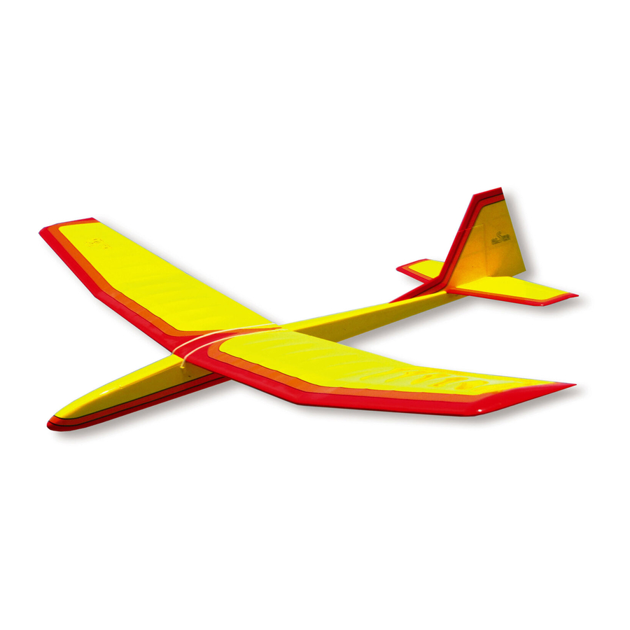
INTRODUCTION
Sailplanes are an easy and relaxing way to learn and enjoy radio control flying. To fly them well, however, takes a lot of skill
and knowledge about the air in which they fly. The RISER was designed with the beginner and sport flier in mind to create a
"floater" that's docile and predictable in flight. The RISER'S gentle handling characteristics doesn't mean it lacks
performance. Experts will find the RISER is capable of holding its own in two-meter sailplane competition.
The versatile RISER can even make a good R/C trainer! Many model clubs around the country like to train student pilots on
a sailplane because of their gentle and slow speed flying characteristics. The slow speed allows the beginner ample time to
develop the skills that are necessary for flying radio controlled models. If you have never flown an R/C model before, we
strongly recommend that you obtain the assistance of a skilled R/C pilot before attempting to fly your Riser for the first time.
Instructions for installing the optional wing spoilers are included with the kit on a separate sheet. Spoilers are essential for
making consistent spot landings and for other multi-task soaring events. Since they aren't necessary for everyday fun flying,
the materials for adding spoilers to your RISER are not included in the kit.
Notes Before Beginning Construction
Any references to right or left refers to your right or left as if you were seated in the cockpit.
To build good flying models, you need a good straight building board. Crooked models don't fly well! The building board can
be a table, a workbench, a reject "door core" from the lumber yard, or whatever - as long as it is perfectly flat and untwisted.
Cover the top surface of the building board with a piece of celotex-type wall board or foam board, into which pins can be
easily pushed. Don't hesitate to use plenty of pins during assembly to hold drying parts in correct position.
When pinning and gluing parts directly over the full-size plans, cover the plan with wax paper or plastic kitchen wrap to
prevent gluing the parts to the plans.
Advertisement
Table of Contents

Related Manuals for SIG RISER SIGRC52


Summary of Contents for SIG RISER SIGRC52
- Page 1 INTRODUCTION Sailplanes are an easy and relaxing way to learn and enjoy radio control flying. To fly them well, however, takes a lot of skill and knowledge about the air in which they fly. The RISER was designed with the beginner and sport flier in mind to create a "floater"...
- Page 2 Don't use a ball point pen for making marks on the model during construction. If not sanded off, these ink marks will show through the model's final finish. Use a pencil instead of a pen. Identifying Kit Parts Leave all die-cut parts in the sheets until needed in construction. Then remove the pieces from the sheets carefully. If difficulty is encountered, do not force the part from the sheet - use a modeling knife to cut it free.
-
Page 3: Radio Equipment Requirements
With CA, you can virtually build a structure from start to finish without having to wait for the glue to dry. Most brands, including SIG CA, come in three different viscosities: thin, medium, and thick. -
Page 4: Wing Construction
You can't get along without a good sanding block An assortment of different size sanding blocks are indispensable tools for model construction. A good general purpose block can be made by wrapping a 9"x11" sheet of sandpaper around a piece of hardwood or plywood. Use three screws along one edge to hold the overlapped ends of the sandpaper. - Page 5 a. Glue and pin the 3/16"x1/4" top spruce spar in place. b. Glue and pin the shaped leading edge in place. 9. Cut vertical grain pieces of 1/16"x3" balsa sheet for spar shear webs. Glue and pin these in place. Note that these extend oniy out to the fourth rib bay.
- Page 6 Outboard Wing a. Pin down the 1/16"x1" bottom sheeting. b. Pin down the 1/16"x3/16" spar cap strip. c. Pin down the 1/4"x1" trailing edge over the plans. 17. Cut pieces of 1/16"x3/16" balsa for the bottom rib cap strips. Glue and pin these as indicated on the plans. 18.
- Page 7 26. Glue and pin the 1/8"x1/4" spruce top spar in place. a. Glue the 1/16"x3/16" top spar cap strip on top of the spar. b. Glue and pin the 1/16"x1" top sheeting in place. a. Cut pieces of 1/16"x3/16" balsa for top rib cap strips.
- Page 8 39. Use the patterns supplied to make two WTT's and two WTB's. Cut these from the scrap 3/32" die-cut plywood brace 40. Trial fit the dihedral braces WTT & WTB. Trim the ribs if necessary, but do not glue the dihedral braces in yet. Repeat these procedures for the other outboard wing panel so that you will have one left panel and one right panel.
-
Page 9: Optional Spoilers
STOP: If you wish to add the spoiler option it.js best to do it before proceeding to the next step. (See "Optional Spoilers" at the end of this section). 44. Position the two wing halves over the plan. Pin the right half down so that its inboard panel is flat on the plan. - Page 10 4. Cut a piece of 1/16" x 1/2" balsa sheeting and glue in place on top of the 1/8" sq. balsa and flush with the top of the wing. 5. Cut a piece of 3/16" x 1/4" balsa to fit in between the ribs as shown on the plans. Drill a 1/8" hole through the center of it to allow the plastic tubing to fit through.
-
Page 13: Fuselage Construction
FUSELAGE CONSTRUCTION 49. Drill or cut out the 5/32" dowel holes in the fuselage sides. This will locate the holes after the plywood doublers have been glued in place. a. Cut pieces of 1/4" triangle stock, and b. 1/8"x3/16" balsa as indicated on the printed fuselage sides. 51. - Page 14 60. Pin the side in position over the top view of the plan. 61. Epoxy glue the other fuselage side to F-2 and F-3 over the plans. Check with a square before the glue sets up. 62. Pull the fuselage sides together at the rear using square weights (pieces of scrap iron shown here) and glue together. 63.
- Page 15 70. Secure the servo, using the manufacturer's mount or mount on hardwood rails. See "Radio Installation" for more information on mounting servos. 71. Cut off 2-1/2" at the threaded end of one of the threaded rods. Put a "Z" bend (or a "L"...
- Page 16 80. Mark a line 3" from the end on the fuselage top hatch sheet (1/4"x2-1/4"x8" balsa). This will indicate where to cut the hatch apart from the rest of the top. 81. Tack glue the top hatch sheet onto the fuselage.
-
Page 17: Tail Construction
92. Block sand all edges to smooth out any rough areas. 93. Remove the hatch and glue in a piece of scrap 1/8" Lite-ply for the hatch hold- down plate "HH" as indicated on the plans. Drill through hatch for the 2- 56x1/2"... - Page 18 101. Glue and pin the 1/8"x3/16" cross braces in place over the plan. 102. Completed stabilizer ready for sanding. 103. Block sand the stabilizer to smooth any rough areas. Be sure to sand the print off of the wood. 104. With a sanding block, shape the tips as indicated on the plans. Round the leading edge and the tips. 105.
-
Page 19: Final Assembly
Hinging The Control Surfaces with Sig Easy Hinges Sig's famous EASYHINGES have been included with your Riser kit for hinging the rudder and the elevator. Even though they are obviously super thin, EASYHINGES are actually a three-part laminate. - Page 20 Supercoat. For flexed. You may notice a slight stiffness in the joint. This can be that finishing touch, use Sig Super Trim eliminated by flexing the surface to full deflection each direction a self-adhesive trim sheets to add a bit of couple of dozen times.
- Page 21 Follow their instructions closely when applying the material, as different brand coverings can have slightly different handling characteristics and application temperatures. However, the basic techniques for applying iron-on plastic coverings of any brand are similar, and the following hints and photos should be helpful.
-
Page 22: Radio Installation
9. Cover the bottom of a fuselage first. When doing compound curves, as on the nose shown here, be sure to leave extra material around that area. Grip the covering and apply heat. As the covering becomes pliable pull the covering around the curve. -
Page 23: Receiver And Battery Installation
Elevator And Rudder Hookup Attach a small nylon control horn to the rudder and another to the elevator using #2x1/2" sheet metal screws. Mount the rudder control horn to the left side of the rudder and the elevator control horn on the bottom of the right elevator half, as shown on the plans. - Page 24 Let go and observe which wing panel to-build Sig Power Pods. The pod's falls to the table. Add very small amounts of weight to the opposite wing tip until main advantage is that it requires much it will balance on the dihedral joint at the center of the wing.
-
Page 25: Thermal Soaring
The main thing to remember when flying a sailplane is not to over control. If the model does get out of control, and you have sufficient altitude, a glider is so stable that you can usually just let go of the sticks momentarily and the model will right itself. -
Page 26: Slope Soaring
Now that the sailplane is at altitude, it is time to go thermal hunting. Start by trimming the RISER for a nice flat glide and head upwind flying a zig-zag pattern. Never cover the same ground twice while searching for thermals. Be looking for areas where you can see heat waves radiating up, or hawks circling, or swirling "dust devils"... - Page 27 LIMIT OF LIABILITY: In use of our products, Sig Mfg. Co.'s only obligation shall be to replace such quantity of the product proven to be defective. User shall determine the suitability of the product for his or her intended use and shall assume all risk and liability in connection...
Need help?
Do you have a question about the RISER SIGRC52 and is the answer not in the manual?
Questions and answers