Table of Contents
Advertisement
Quick Links
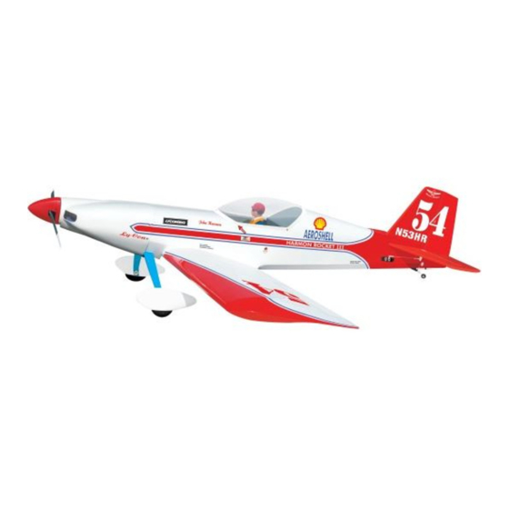
HARMON ROCKET III
Hand-made Almost Ready to Fly R/C Model Aircraft
Specifications
Wingspan---------------------------------------- 50.4 in---------------------------- 128cm.
Wing area--------------------------------------- 558sq.in----------------------- 36 sq.dm.
Approximate flying weight------------------ 6.2-6.4lbs-------------------- 2.8-2.9kg.
Length-------------------------------------------- 51.6 in---------------------------- 131cm.
Recommended engine size---------------.40-.46 cu.in-------------------- 2-stroke.
Radio System required 4 channel with 6 servos.
Flying skill level Intermediate/advanced.
Kit features.
•
Ready-made—minimal assembly & finishing required.
•
Ready-covered covering.
•
Photo-illustrated step-by-step Assembly Manual.
Made in Vietnam.
ASSEMBLY MANUAL
.52-.82 cu.in--------------------4-stroke.
Advertisement
Table of Contents

Related Manuals for Seagull Models HARMON ROCKET III


Summary of Contents for Seagull Models HARMON ROCKET III
- Page 1 HARMON ROCKET III Hand-made Almost Ready to Fly R/C Model Aircraft ASSEMBLY MANUAL Specifications Wingspan---------------------------------------- 50.4 in---------------------------- 128cm. Wing area--------------------------------------- 558sq.in----------------------- 36 sq.dm. Approximate flying weight------------------ 6.2-6.4lbs-------------------- 2.8-2.9kg. Length-------------------------------------------- 51.6 in---------------------------- 131cm. Recommended engine size---------------.40-.46 cu.in-------------------- 2-stroke. .52-.82 cu.in--------------------4-stroke. Radio System required 4 channel with 6 servos.
-
Page 2: Fuselage Assembly
ARTF , yet the design allows the aeroplane to be kept light. You will find that most of the work has been done for you already.Flying the Harmon Rocket III is simply a joy. - Page 3 Please trial fit all parts. Make sure you have the correct parts and that they fit and are aligned properly before gluing! This will ensure proper as- sembly as the Harmon Rocket III is made from natural materials and minor adjustments may have to be made.
-
Page 4: Hinging The Ailerons
HARMON ROCKET III. Instruction Manual. 4)Deflect the aileron and completely HINGING THE AILERONS. saturate each hinge with thin C/A glue. The ailerons front surface should lightly contact the Note: The control surfaces, including the wing during this procedure. Ideally, when the ailerons, elevators, and rudder, are hinges are glued in place, a 1/64”... -
Page 5: Hinging The Elevators
HARMON ROCKET III. Instruction Manual. 8) After both ailerons are securely hinged, 4)Deflect the elevator and completely firmly grasp the wing panel and aileron to saturate each hinge with thin C/A glue. The make sure the hinges are securely glued and elevators front surface should lightly contact cannot be pulled out. -
Page 6: Hinging The Rudder
HARMON ROCKET III. Instruction Manual. Note: The hinge is constructed of a special HINGING THE RUDDER. material that allows the C/A to wick or penetrate and distribute throughout the hinge, securely 1) Carefully remove the rudder from one of bonding it to the wood structure of the fuselage the fuselage panel. -
Page 7: Wing Assembly
HARMON ROCKET III. Instruction Manual. Carefully slide the two wing halves together WING ASSEMBLY. and firmly press them together, allowing the NOTE: We highly recommend using 30 excess epoxy to run out. There should not be minute epoxy as it is stronger and provides any gap in the wing halves. -
Page 8: Installing The Aileron Servos
HARMON ROCKET III. Instruction Manual. Remove covering. Using a small weight ( Weighted fuel pick-up ) and thread, feed the string through works well the wing as indicated. Glue attached. INSTALLING THE AILERON SERVOS. Small weight. Thread. Thread. Servo. Small weight. -
Page 9: Installing The Aileron Linkage
HARMON ROCKET III. Instruction Manual. Thread. Thread. Plastic tape. AILERON LINKAGE. INSTALLING THE AILERON LINKAGE. 1) Using a ruler & pen to draw a straight line as below picture. Straight line. Install the aileron servo tray into the servo mount. - Page 10 HARMON ROCKET III. Instruction Manual. 2) Locate the two nylon control horns, Aileron pushrod rod. two nylon control horn backplates and two Pen. machine screws. 2MM x 30 MM. Clevis. 3) Position the aileron horn on the bottom side of aileron. The clevis attachment holes should be positioned over the hinge line.
-
Page 11: Engine Mount
HARMON ROCKET III. Instruction Manual. 2) Using a modeling knife, cut one length ENGINE MOUNT. of silicon fuel line . Connect one end of the line to the weighted fuel pickup and the other See pictures below: end to the nylon pickup tube. -
Page 12: Mounting The Engine
HARMON ROCKET III. Instruction Manual. the flashing around the tank opening using a Vent tube. modeling knife. If flashing is present, make sure none falls into the tank. 6) With the stopper assembly in place, the weighted pickup should rest about 3/8”... - Page 13 HARMON ROCKET III. Instruction Manual. COWLING. 4.2- 4.5mm. 1) Slide the fiberglass cowl over the en- 4mm X 30mm. gine and line up the back edge of the cowl with the marks you made on the fuselage then trim and cut.
-
Page 14: Installing The Spinner
HARMON ROCKET III. Instruction Manual. 1.5mm wire (needle valve). INSTALLING THE SPINNER. Slide the cowl back over the engine 1) Install the spinner backplate, propeller and and secure it in place using four 3mm x 12mm spinner cone. The spinner cone is held in wood screws. - Page 15 HARMON ROCKET III. Instruction Manual. WHEEL AND WHEEL PANTS. PARTS REQUIRED (2) Washer. (2) Wheel Collar. Axle. Nut. 1) Assembling and mounting the wheel Wheel. pants as shown below pictures. Nut. 10MM. 2) Follow diagram below for wheel pant installation: Plywood Washer.
-
Page 16: Elevator - Rudder Servo Installation
HARMON ROCKET III. Instruction Manual. ELEVATOR - RUDDER SERVO INSTALLATION. Locate and cut out the covering film from the servo holes in both sides of fuselage. 4) A drop of C/A glue on the wheel collar screws will help keep them from coming lose during operation. - Page 17 HARMON ROCKET III. Instruction Manual. 5) Remove the stabilizer. Using the lines Center line. you just drew as a guide, carefully remove the covering from between them using a model- ing knife. 2)Using a modeling knife, carefully remove the covering at mounting slot of horizontal sta- bilizer ( both side of fuselage).
-
Page 18: Vertical Stabilizer Installation
HARMON ROCKET III. Instruction Manual. Covered wood filler piece. 3) While holding the vertical stabilizer VERTICAL STABILIZER firmly in place, use a pen and draw a line on INSTALLATION. each side of the vertical stabilizer where it meets the top of the fuselage. -
Page 19: Control Horn Installation
HARMON ROCKET III. Instruction Manual. 5) Slide the vertical stabilizer back in CONTROL HORN INSTALLATION. place. Using a triangle, check to ensure that 1) Locate the two nylon control horns, two the vertical stabilizer is aligned 90º to the hori- nylon control horn backplates and four zontal stabilizer. -
Page 20: Mounting The Tail Wheel Bracket
HARMON ROCKET III. Instruction Manual. 5) Rudder pushrods assembly follow Elevator control horn. picture below. Pushrod. Control horn. Rudder control horn. Metal clevis. Connector. ELEVATOR - RUDDER PUSHROD INSTALLATION. MOUNTING THE TAIL WHEEL BRACKET. Thread one nylon adjustable control horn on to each aileron control rod. Thread... -
Page 21: Installing The Switch
HARMON ROCKET III. Instruction Manual. 5) Slide the clasp back into position and 3) Secure the servos with the screws pro- carefully glue it into place using Kwik Bond Thin vided with your radio system. C/A. Hold the clasp in place until the glue com- pletely cures. -
Page 22: Installing The Receiver And Battery
Band 1) We highly recommend setting up the Modified Servo Arm Harmon Rocket III using the control throws listed at right. We have listed control throws for both Low Rate (initial test flying/sport fly- ing) and High Rate (aerobatic flying). -
Page 23: Preflight Check
Do not use the aerobatic settings for 2) Check every bolt and every glue joint initial test flying or sport flying. in the Harmon Rocket III to ensure that ev- erything is tight and well bonded. 3) Double check the balance of the air- 4) By moving the position of the adjust- plane.
Need help?
Do you have a question about the HARMON ROCKET III and is the answer not in the manual?
Questions and answers