Kyocera KM-6030 Service Manual
Hide thumbs
Also See for KM-6030:
- Operation manual (124 pages) ,
- Ftp transmission manual (2 pages) ,
- Command reference manual (410 pages)
Table of Contents
Advertisement
Quick Links
Advertisement
Table of Contents

Related Manuals for Kyocera KM-6030


Summary of Contents for Kyocera KM-6030
-
Page 1: Service Manual
KM-6030 KM-8030 SERVICE MANUAL Published in March 2006 842FB114 Rev. 4... - Page 2 CAUTION Danger of explosion if battery is incorrectly replaced. Replace only with the same or equivalent type recommended by the manufacturer. Dispose of used batteries according to the manufacturer’s instructions. CAUTION Double-pole/neutral fusing.
-
Page 3: Revision History
Revision history Revision Date Replaced pages Remarks 24 June 2005 Overall revised 2 December 2005 Overall revised 20 March 2006 Overall revised... - Page 4 This page is intentionally left blank.
-
Page 5: Safety Precautions
Safety precautions This booklet provides safety warnings and precautions for our service personnel to ensure the safety of their customers, their machines as well as themselves during maintenance activities. Service personnel are advised to read this booklet carefully to familiarize themselves with the warnings and precautions described here before engaging in maintenance activities. - Page 6 Safety warnings and precautions Various symbols are used to protect our service personnel and customers from physical danger and to prevent damage to their property. These symbols are described below: DANGER: High risk of serious bodily injury or death may result from insufficient attention to or incorrect compliance with warning messages using this symbol.
-
Page 7: Installation Precautions
1.Installation Precautions WARNING • Do not use a power supply with a voltage other than that specified. Avoid multiple connections to one outlet: they may cause fire or electric shock. When using an extension cable, always check that it is adequate for the rated current....................•... -
Page 8: Specifications 1
2.Precautions for Maintenance WARNING • Always remove the power plug from the wall outlet before starting machine disassembly....• Always follow the procedures for maintenance described in the service manual and other related brochures............................• Under no circumstances attempt to bypass or disable safety features including safety mechanisms and protective circuits. - Page 9 • Do not remove the ozone filter, if any, from the copier except for routine replacement..... • Do not pull on the AC power cord or connector wires on high-voltage components when removing them; always hold the plug itself...................... •...
-
Page 11: Table Of Contents
2FB/2FC CONTENTS 1-1 Specifications 1-1-1 Specifications............................1-1-1 1-1-2 Parts names............................1-1-3 (1) Copier..............................1-1-3 (2) Operation panel..........................1-1-5 1-1-3 Cross section view ..........................1-1-6 1-1-4 Drive system ............................1-1-7 (1) Drive system 1 (Optical section)......................1-1-7 (2) Drive system 2 (Cassette paper feed)....................1-1-8 (3) Drive system 3 (Deck paper feed).....................1-1-9 (4) Drive system 4 (Deck lift) ........................1-1-9 (5) Drive system 5 (Vertical paper feed) ....................1-1-10 (6) Drive system 6 (MP tray paper feed)....................1-1-11... - Page 12 2FB/2FC-4 (2) Paper misfeed detection conditions ....................1-5-2 (3) Paper misfeeds ..........................1-5-10 1-5-2 Self-diagnosis ............................1-5-24 (1) Self-diagnostic function ........................1-5-24 (2) Self diagnostic codes ........................1-5-26 1-5-3 Image formation problems ........................1-5-46 (1) No image appears(entirely white)....................1-5-48 (2) No image appears(entirely black)....................1-5-49 (3) Image is too light..........................1-5-50 (4) Background is visible........................1-5-51 (5) A white line appears longitudinally.
- Page 13 2FB/2FC-4 (31) The LSU fan motor does not operate....................1-5-62 (32) Developing fan motor 1 or 2 does not operate................1-5-63 (33) The image formation fan motor does not operate................1-5-63 (34) The developing duct fan motor does not operate................1-5-63 (35) PWB fan motor 1 or 2 does not operate..................1-5-64 (36) The power source fan motor does not operate.
- Page 14 2FB/2FC-3 1-6 Assembly and Disassembly 1-6-1 Precautions for assembly and disassembly....................1-6-1 (1) Precautions ............................1-6-1 (2) Running a maintenance item......................1-6-2 1-6-2 Paper feed section ..........................1-6-3 (1) Detaching and refitting the paper feed pulley, forwarding pulley and separation pulley of cassette 1 and 2....................1-6-3 (2) Detaching and refitting the paper feed pulley, forwarding pulley and separation pulley of cassette 3 and 4....................1-6-10 (3) Pressure adjustment of separation pulley (reference)..............1-6-14...
- Page 15 2FB/2FC-3 (4) Detaching and refitting the cleaning felt ..................1-6-73 (5) Detaching and refitting the fuser thermostat ...................1-6-75 (6) Detaching and refitting the fuser thermistor ..................1-6-75 (7) Detaching and refitting the fuser heater M, S and L................1-6-76 (8) Detaching and refitting the heat roller .....................1-6-79 (9) Detaching and refitting the heat roller separation claws..............1-6-80 (10) Detaching and refitting the fuser eject upper roller................1-6-81 1-6-11 Document processor (DP) section ......................1-6-82...
- Page 16 2FB/2FC-2.0 (6) Switches and sensors (DP) .......................2-2-9 (7) Others (DP) .............................2-2-10 2-3 Operation of the PWBs 2-3-1 AC power source PWB ...........................2-3-1 2-3-2 DC power source PWB ...........................2-3-4 2-3-3 Main PWB ...............................2-3-8 2-3-4 Engine PWB............................2-3-17 2-3-5 Scanner PWB ............................2-3-25 2-3-6 CCD PWB .............................2-3-29 2-3-7 Deck PWB.............................2-3-32 2-3-8 Cassette PWB............................2-3-37 2-3-9 Duplex PWB............................2-3-40...
-
Page 17: Specifications
2FB/2FC 1-1 Specifications 1-1-1 Specifications Copier Type ..........Console Copying system ......Indirect electrostatic system Originals.......... Sheets, books and three-dimensional objects Maximum size: A3/11" x 17" Original feed system ....... Fixed Copy paper ........Weight Cassette: 60 - 160 g/m MP tray: 45 - 200 g/m Types Cassette: Plain paper, colored paper... - Page 18 2FB/2FC Developing system ......Dry, reverse developing (single component system) Developer: 1-component, magnetism toner Toner replenishing: Automatic from a toner container Transfer system ......Transfer belt, approximately 1.5 kV Separation system ......Transfer belt and separation claws Fusing system......... Heat roller Heat source: Halogen heaters 120 V specifications Main 1080 W, sub 500 W, small size 1000 W...
-
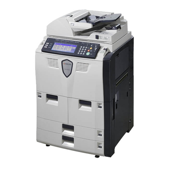
Page 19: Parts Names
2FB/2FC 1-1-2 Parts names (1) Copier Figure 1-1-1 Operation panel 12. Handles Operation panel lock lever 13. Main power switch Document processor (DP) 14. Main power switch cover Cassette 1 15. Document processor bottom cover Cassette 2 16. Original size indicator plates Cassette 3 17. - Page 20 2FB/2FC Figure 1-1-2 22. Original table 32. Paper conveyor 23. Original width guides 33. Knob A1 24. Cleaning cloth compartment 34. Lever A2 25. Original loaded Indicator 35. Knob A3 26. Document processor top cover 36. Duplex unit 27. Ejection guide 37.
- Page 21 2FB/2FC (2) Operation panel Figure 1-1-3 Brightness adjustment dial 11. Job accounting key Copy key/indicator 12. Interrupt key/indicator Printer key/indicator 13. Energy saver key/indicator Scanner key/indicator 14. Touch panel Document management key/indicator 15. Numeric keys Print management key/indicator 16. Reset key Repeat copy key/indicator 17.
-
Page 22: Cross Section View
2FB/2FC 1-1-3 Cross section view Light path Paper and original path Figure 1-1-4 Paper feed section Cleaning section Main charging section PTC section Optical section Fuser section Drum section 10. Feedshift and eject section Developing section 11. Duplex section Transfer section 12. -
Page 23: Drive System
2FB/2FC 1-1-4 Drive system (1) Drive system 1 (Optical section) Figure 1-1-5 Scanner motor Pulley scanner Belt scanner Front/Rear wire scanner Drum pulley Pulley moving idle Gear Z36 Pulley scanner Gear Z18/39 10. Pulley scanner 1-1-7... -
Page 24: Drive System 2 (Cassette Paper Feed)
2FB/2FC (2) Drive system 2 (Cassette paper feed) Figure 1-1-6 Paper feed motor 3 Paper feed motor 4 Gear cassette feed Gear cassette feed Upper gear paper feed Upper gear paper feed Joint drive 10. Joint drive Gear 16 idle 11. -
Page 25: Drive System 3 (Deck Paper Feed)
2FB/2FC (3) Drive system 3 (Deck paper feed) Figure 1-1-7 Paper feed motor 1 11. Upper gear paper feed Gear idle 50 12. Gear 16 idle Gear idle B 13. Pulley Leading feed Gear 27/24 one-way L 14. Paper feed motor 2 Gear deck 15. -
Page 26: Drive System 5 (Vertical Paper Feed)
2FB/2FC (5) Drive system 5 (Vertical paper feed) Figure 1-1-9 Vertical feed motor Gear 38 vertical feed Belt vertical feed Pulley 32 vertical feed Pulley 26 vertical feed Gear 38 vertical feed Gear 32 vertical feed 10. Gear 38 vertical feed Gear 38 vertical feed 11. -
Page 27: Drive System 6 (Mp Tray Paper Feed)
2FB/2FC (6) Drive system 6 (MP tray paper feed) Figure 1-1-10 MP feed motor Gear 54 MP tray Gear 54 MP tray Gear 44 MP tray 1-1-11... -
Page 28: Drive System 7 (Paper Conveying)
2FB/2FC (7) Drive system 7 (Paper conveying) Figure 1-1-11 Registration motor Gear 43 feed Gear 47 feed Gear 25 feed A Gear 21 feed 10. Gear 16 registration Gear Z18H feed 11. Pulley 26 one-way feed Gear Z18H-Z18S feed 12. Pulley 26 one-way feed Gear 16 registration 13. -
Page 29: Drive System 8 (Drive Motor And Developing Motor Drive Trains)
2FB/2FC (8) Drive system 8 (Drive motor and developing motor drive trains) Figure 1-1-12 Drive motor 10. Gear 44 Gear 183 drum drive 11. Gear 40 DLP Shaft drum drive 12. Gear 25 DLP Belt cleaning drive 13. Gear 70 DLP Pulley tension 14. -
Page 30: Drive System 9 (Transfer Motor, Fuser Motor Drive Train)
2FB/2FC (9) Drive system 9 (Transfer motor, fuser motor drive train) Figure 1-1-14 Transfer motor 14. Gear 29 duplex Gear 82 TFR 15. Gear 19/33 eject Gear 36 TFR 16. Pulley 20 TC ground roller 17. Pulley 24 eject Coupling TC drive 18. - Page 31 2FB/2FC Figure 1-1-15 Duplex section Gear 28/35 Pulley DU tension Belt rear feed Gear DU 30 one-way 10. Gear 37/24 DU conveying Duplex switchback motor 11. Gear 27/24 one-way L Gear 24 DU conveying 12. Pulley 30 DU Duplex feed motor 13.
-
Page 32: Drive System 10 (Toner Motor Drive Train)
2FB/2FC (10) Drive system 10 (Toner motor drive train) Figure 1-1-17 Toner motor Gear Z70/Z16S Gear Z56S/Z20S Gear 38 Gear joint CONT Coupling container 1-1-16... -
Page 33: Drive System 11 (Document Processor)
2FB/2FC (11) Drive system 11 (Document processor) Figure 1-1-18 Original conveying motor 22. Gear CIS roller 20 23. Gear CIS idle 21 Timing belt C motor 244 24. Gear CIS idle 21 Pulley C roller 99 25. Gear CIS roller 20 Original registration motor 26. -
Page 34: Drum
2FB/2FC 1-2Handling Precautions 1-2-1 Drum Note the following when handling or storing the drum. • When removing the drum, never expose the drum surface to strong direct light. ° ° ° ° • Keep the drum at an ambient temperature between -20 C/-4 F and 40 C/104... - Page 35 2FB/2FC a: 680 mm/26 " b: 783 mm/30 " 13/16 c: 1190 mm/46 " d: 1860 mm/73 " 3/16 e: 1465 mm/57 " 11/16 f: 1530 mm/60 " 3/16 Figure 1-2-1 Installation dimensions 1-2-2...
-
Page 36: Unpacking And Installation
2FB/2FC-4 1-3Installation 1-3-1 Unpacking and installation (1) Installation procedure Start Unpacking. Taking out the machine. Remove the tapes, pins, spacers and sheet. Remove the screws. Remove the tapes of transfer section and duplex unit. Installing the toner container. Adjusting the machine levelness. Connecting the power cord. - Page 37 2FB/2FC-2.0 Unpacking. Figure 1-3-1 Unpacking Main body 16. Sheet Skid 17. DP sheet Slopes 18. Rear sheets Lower left spacer 19. Hinge joints Lower right spacer 20. Plastic bag Upper left spacer 21. Operation guide Upper right spacer 22. Casette size plates Upper spacer 23.
- Page 38 2FB/2FC Taking out the machine. When taking out the machine, a space for machine rear requires approximately 2 m. 1. Remove the hinge joints, and then remove the upper case, the upper spacer, the upper left spacer, the upper right spacer, the outer case and the supports.
- Page 39 2FB/2FC 5. Remove the machine cover and pull out the handles on machine left and right. 6. Lift the machine each left and right one side, and then remove the lower left and right spacers. 7. Move the machine alongside slopes to slide to the floor.
- Page 40 2FB/2FC Remove the tapes, pins, spacers and sheet. 1. Remove nineteen tapes, DP spacer and DP sheet. DP spacer Tape Tapes Tapes DP sheet Tape Tape Tape Tapes Tapes Tapes Figure 1-3-4 2. Remove four tapes, two pins for light source Pin for unit 1 and pin for light source unit 2.
- Page 41 2FB/2FC 3. 120 V specifications Remove the two tapes of power cord. 230 V specifications Remove the tape of power cord. 120 V specifications 230 V specifications Tape Tapes Figure 1-3-6 4. Remove four tapes and two rear sheets. Tapes Tape Rear sheet Tape...
- Page 42 2FB/2FC 6. Pull out cassette 1 and 2, then remove two Deck spacer deck spacers. 7. Remove the tape from the deck spacer of Guide case cassette 1 and then remove the guide case. Tape Deck spacer Figure 1-3-9 8. Pull out cassette 3 and 4, then remove two cassette spacers and tapes.
- Page 43 2FB/2FC-4 Remove the tapes of transfer section and duplex unit. 1. Pull out the paper conveying unit. 2. Remove the tape from the transfer section. 3. Refit the conveying unit. Tape Figure 1-3-13 4. Pull out the duplex unit. 5. Remove two tapes from the duplex unit. 6.
- Page 44 2FB/2FC-3 Installing the toner container. 1. Set the toner container on a flat surface. * When setting it down with the gear-end fac- ing down, place some cushioning material underneath. 2. Tap the top of the toner container at least ten times.
- Page 45 2FB/2FC-4 Adjusting the machine levelness. 1. Verify levelness at the four coners of the contact glass using a level gauge, and adjust the level bolts at the bottom of the machine to optimize levelness. Connecting the power cord. 1. Connect the power cord to the inlet on lower left of the machine.
- Page 46 2FB/2FC-2.0 Attaching the language label (230 V specifications only). 1. According to need, attach the correspond language of operation unit label, MP label, DP labels and main power switch label. MP label Figure 1-3-18 DP labels Main power switch label DP label Figure 1-3-19 Installing the guide case.
-
Page 47: Setting Initial Copy Modes
2FB/2FC-3 1-3-2 Setting initial copy modes Factory settings are as follows: Maintenance Contents Factory setting item No. U253 Switching between double and single counts Double count for A3/11" x 17" paper only U254 Turning auto start function ON/OFF U258 Switching copy operation at toner empty detection SINGLE MODE, 200 U260 Changing the copy count timing... -
Page 48: Installing The Key Counter (Option)
2FB/2FC-3 1-3-3 Installing the key counter (option) Key counter installation requires the following parts: Key counter set (P/N 302A369705/2A369705) Contents of the set: Key counter cover (P/N 2A360010) Key counter retainer (P/N 66060030) Key counter cover retainer (P/N 66060022) Key counter mount (P/N 66060040) Key counter socket assembly (P/N 41529210) Four (4) M4 x 6 TP-A screws (P/N B4304060) One (1) M4 x 20 TP-A screw (P/N 7BB100420H/BB040740) -
Page 49: Figure 1
2FB/2FC-3 3. Cut out the aperture plate on the middle right cover using nippers. 4. Pass the 4-pin connector of the key counter through the apertures in the key counter cover retainer and middle right cover, and insert into the 4-pin connector inside the machine. 5. -
Page 50: Installing The Document Finisher (Option)
2FB/2FC-2.0 1-3-4 Installing the document finisher (option) • Output connector of the main machine is non-LPS. Please use the item below interconnecting cable. P/N: 3H327220 Circuit type: Non-LPS Circuit specs.: 24 V DC • Before installing the document finisher, press the Power key on the operation panel to off. Make sure that the Power lamp is off before turning off the main power switch. - Page 51 2FB/2FC-4 3. As shown in the figure, affix the sponge to Finisher the top cover of the finisher after wiping the cover with alcohol. Aligning the bottom of the sponge with the bottom of the top cover, affix the sponge in the center of the cover.
- Page 52 2FB/2FC 7. Remove the screw and pull out the connect- ing rail at the upper part of the finisher. Screw Connecting rail Figure 1-3-28 8. Cut out the hole covers at two locations on the machine. 9. Position the finisher and machine so the long pin of the connect- ing plate aligns with the back hole of the finisher, and the two short pins align with the holes of the connecting rail.
- Page 53 2FB/2FC-4 12. Secure it with the screw removed in step 6. Link lever Screw Figure 1-3-31 Retainer 13. Remove the tape. Remove the four blue screws locking each of the two separate retainers to the intermediate tray and detach both retainers. Blue screws 14.
- Page 54 2FB/2FC 16. Remove the tape inside the finisher. Tape Figure 1-3-34 17. Raise the release handle to open the inter- mediate tray and then remove the four tapes. Tapes Tapes Release handle Figure 1-3-35 18. Load two staple cartridges into the staple holders and press down on them until they Staple holders lock securely into place.
- Page 55 2FB/2FC 20. Insert the two nuts into the main tray. 21. Secure the main tray with two pins. 22. Install the sub tray by inserting it from above into the hole on the finisher. Nuts Main tray Sub tray Hole Pins Figure 1-3-37 23.
- Page 56 2FB/2FC 25. Refit the signal cable cover using the screw. Pass the signal cable through a cut of the signal cable cover as shown in the figure. Signal cable cover Figure 1-3-40 26. Remove the screw from the lower rear cover of the machine.
- Page 57 2FB/2FC [Correcting paper curling] 1. Set the machine in the non-sort mode and run paper through the machine to make a test copy. 2. Check if the paper that is ejected from the finisher is curled. If it is, make the following adjustment.
- Page 58 2FB/2FC 3. Rotate the upper lever by one mark in the direction of the higher numbers. There are 5 marks. 4. Close the front cover. 5. Run paper through the machine and check if it is still curled upward. 6. Repeat steps 1 to 5 until the ejected paper does not curl upward anymore.
-
Page 59: Installing The Side Feeder (Option)
2FB/2FC-2.0 1-3-5 Installing the side feeder (option) • Output connector of the main machine is non-LPS. Please use the item below interconnecting cable. P/N: 3JD27220 Circuit type: Non-LPS Circuit specs.: 24 V DC • Before installing the side feeder, press the Power key on the operation panel to off. Make sure that the Power lamp is off before turning off the main power switch. - Page 60 2FB/2FC M4 x 12 flat-head screw 5. Attach the switch contact plate to the right rear lower cover using the M4 x 12 flat-head screw. Switch contact plate Right rear lower cover Figure 1-3-49 6. Pull out the fixing plate of the side feeder, Right cover and insert it into the bottom of the machine's right cover.
- Page 61 2FB/2FC 9. Open the side feeder’s right cover and top cover, remove the two screws, and remove Screw Screw the anchor bracket. Anchor bracket Figure 1-3-52 10. Set the side feeder on the machine, and connect its signal cable to the connector on the back of the machine.
- Page 62 2FB/2FC [Correcting the inclination] • If the side feeder is not level, perform the following steps to adjust its inclination. 1. Loosen the two adjustment screws. 2. Slide the fixing plate in the direction indicated by the arrow, and then tighten the adjusting screws. 3.
-
Page 63: Installing The Printer Kit (Option)
2FB/2FC-2.0 1-3-6 Installing the printer kit (option) • Before installing the printer kit, press the Power key on the operation panel to off. Make sure that the Power lamp is off before turning off the main power switch. And then unplug the power cable from the wall outlet. Turning off the main power switch before pressing the Power key to off may cause damage to the equipped hard disk. - Page 64 2FB/2FC Install the optional hard disk. 1. Remove the two pins, and then remove the HDD cover. 2. Slide in the hard disk along the rails, and then secure it with the two pins. After installation, the hard disk must be for- matted.
- Page 65 2FB/2FC • Remove the screw of the lower rear cover. Fasten all the cables with the clamp and tighten the M3 screw to fix the clamp. Make sure that the clamp is facing as shown in the figure. M3 screw Clamp Figure 1-3-62 1-3-30...
-
Page 66: Installing The Scanner Kit (Option)
2FB/2FC-2.0 1-3-7 Installing the scanner kit (option) • Before installing the scanner kit, press the Power key on the operation panel to off. Make sure that the Power lamp is off before turning off the main power switch. And then unplug the power cable from the wall outlet. Turning off the main power switch before pressing the Power key to off may cause damage to the equipped hard disk. - Page 67 2FB/2FC • Remove the screw of the lower rear cover. Fasten all the cables with the clamp and tighten the M3 screw to fix the clamp. Make sure that the clamp is facing as shown in the figure. M3 screw Clamp Figure 1-3-66 1-3-32...
-
Page 68: Installing The Security Kit (Option)
2FB/2FC-2.0 1-3-8 Installing the security kit (option) • Before installing the security kit, press the Power key on the operation panel to off. Make sure that the Power lamp is off before turning off the main power switch. And then unplug the power cable from the wall outlet. Turning off the main power switch before pressing the Power key to off may cause damage to the equipped hard disk. - Page 69 2FB/2FC-2.0 3. Insert the board support into the elongate hole. Secure the board support by rotating either clockwise/counterclockwise for 90 degrees. Be careful not to pinch the power cable. 4. Connect the security board to the YC27 con- nector of the main PWB. Secure it with the board support.
-
Page 70: Maintenance Mode
2FB/2FC 1-4 Maintenance Mode 1-4-1 Maintenance mode The copier is equipped with a maintenance function which can be used to maintain and service the machine. (1) Executing a maintenance item Start Enter 10871087 using Maintenance mode is entered. the numeric keys. Enter the maintenance item number using the cursor up/down keys The maintenance item is... -
Page 71: Maintenance Mode Item List
2FB/2FC-3 (2) Maintenance mode item list Section Item Content of maintenance item Initial setting* General U000 Printing out an own-status report U001 Exiting the maintenance mode U002 Setting the factory default data U003 Setting the service telephone number *************** U004 Displaying the machine number U005 Copying without paper... - Page 72 2FB/2FC-3 Section Item Content of maintenance item Initial setting* Optical U060 Adjusting the scanner input properties 12/11 U061 Checking the operation of the exposure lamps U063 Adjusting the shading position U064 Adjusting the CCD level U065 Adjusting the scanning magnification U066 Adjusting the scanner leading edge registration 10/0...
- Page 73 2FB/2FC-3 Section Item Content of maintenance item Initial setting* Developing U135 Checking toner motor operation U137 Checking the toner level detection sensor U147 Setting for toner applying operation 6 (MODE6) U152 Setting developing motor mode U157 Checking the developing drive time U158 Checking the developing count Fuser and...
- Page 74 2FB/2FC-3 Section Item Content of maintenance item Initial setting* Operation U248 Changing the paper ejection device settings panel/ Adjustment of registration stop timing in punch mode Optional units Adjustment of the paper stop timing in punch mode Punch-hole scrap count *1, *2 Setting the booklet stapling position 0/0/0...
- Page 75 2FB/2FC-3 Section Item Content of maintenance item Initial setting* Other U901 Checking/clearing total copy counts by paper feed location *1, *2 U903 Checking/clearing the paper jam count *1, *2 U904 Checking/clearing the call for service counts *1, *2 U905 Checking/clearing count by optional devices U906 Resetting partial operational control *1, *2...
-
Page 76: Contents Of The Maintenance Mode Items
2FB/2FC-3 (3) Contents of the maintenance mode items Maintenance Description item No. Printing out an own-status report U000 Description Prints out a list of the current settings of all maintenance items, and occurrences of paper jams and service calls. Purpose To check the current setting of the maintenance items, or the occurrences of paper jams and service calls. - Page 77 2FB/2FC Maintenance Description item No. Setting the service telephone number U003 Description Sets the telephone number to be displayed when a service call code is detected. Purpose To set (during initial set-up of the machine) the telephone number for contacting service. Method Press the start key.
- Page 78 2FB/2FC-3 Maintenance Description item No. Copying without paper U005 Description Simulates the copy operation without paper feed. Purpose To check the overall operation of the machine. Remarks Execute this maintenance mode after pull out all four cassettes. Method 1. Press the start key. The screen for selecting an item is displayed. 2.
- Page 79 2FB/2FC-3 Maintenance Description item No. Displaying the ROM version U019 Description Displays the part number for the ROM fitted to each PWB. Purpose To check the part number or to decide, based on the last digit of the number, if the newest version of ROM is installed.
- Page 80 2FB/2FC-3 Maintenance Description item No. Memory initializing U021 Description Initializes all settings, except those pertinent to the type of copier, namely each counter, service call history and mode setting. Also initializes backup RAM according to region specification selected in maintenance item U252 “Setting the destination.”...
- Page 81 2FB/2FC-2.0 Maintenance Description item No. Evacuation of backup data U026 Description Transfers the backup data of the main PWB to the EEPROM. Purpose Used when replacing the main PWB. Method 1. Press the start key. The screen for executing is displayed. 2.
- Page 82 2FB/2FC-2.0 This page is intentionally left blank. 1-4-13...
- Page 83 2FB/2FC Maintenance Description item No. Checking the operation of the motors U030 Description Drives each motor. Description To check the operation of each motor. Method 1. Press the start key. The screen for selecting an item is displayed. 2. Select the motor to be operated. The selected item is displayed in reverse and the operation starts. Two or more motors can be selected.
- Page 84 2FB/2FC Maintenance Description item No. Checking switches for paper conveying U031 Description Displays the ON/OFF status of each paper detection switch on the paper conveying path. Purpose To check the operation of the switches for paper conveying. Method 1. Press the start key. A list of switches, the on-off status of which can be checked, are displayed. 2.
- Page 85 2FB/2FC Maintenance Description item No. Checking the operation of the solenoids U033 Description Applies current to each solenoid in order to check its ON status. Purpose To check the operation of each solenoid. Method 1. Press the start key. The screen for selecting an item is displayed. 2.
- Page 86 2FB/2FC-3 Maintenance Description item No. Checking the operation of the fan motors U037 Description Drives the fan motors. Description To check the operation of the fan motors. Method 1. Press the start key. The screen for selecting an item is displayed. 2.
- Page 87 2FB/2FC-3 Maintenance Description item No. Setting the adjustment of the motor speed U053 Description Performs fine adjustment of the speeds of the motors. Purpose Basically, the setting need not be changed. Modify settings by interlock setting only if faulty images occur. Method Press the start key.
- Page 88 2FB/2FC-3 Maintenance Description item No. Setting: separate setting U053 1. Select Separate setting at the screen for selecting an item. 2. Select the item to be adjusted. The selected item is displayed in reverse. 3. Change the value using the cursor up/down keys. Display Description Setting...
- Page 89 2FB/2FC-3 Maintenance Description item No. Setting fan motor mode U059 Description Specifies whether to rotate the fan motor in sleep mode. Purpose To rotate the fan motor for certain period of time to prevent rise in temperature inside the machine in sleep mode.
- Page 90 2FB/2FC-3 This page is intentionally left blank. 1-4-19...
- Page 91 2FB/2FC-3 Maintenance Description item No. Adjusting the scanner input properties U060 Description Adjusts the image scanning density in text, text and photo, or photo mode. Purpose Used when the entire image appears too dark or light. Adjusts when replacing CIS of DP. Method Press the start key.
- Page 92 2FB/2FC-3 Maintenance Description item No. Adjusting the shading position U063 Description Changes the shading position of the scanner. Purpose Used when the white line continue to appear longitudinally on the image after the shading plate is cleaned. This is due to flaws or stains inside the shading plate. To prevent this problem, the shading position should be changed so that shading is possible without being affected by the flaws or stains.
- Page 93 2FB/2FC Maintenance Description item No. Adjusting the scanning position for originals from the DP U068 Description Adjusts the position for scanning originals from the document processor. Performs the test copy at the five scanning positions after adjusting. Purpose Used when the image fogging occurs because the scanning position is not proper when the document proces- sor is used.
- Page 94 2FB/2FC Maintenance Description item No. Checking the scanner operation U073 Description Simulates the scanner operation under the arbitrary conditions. Purpose To check the scanner operation. Implementation 1. Press the start key. The screen for selecting an item is displayed. 2. Select the item to be operated. The selected item is displayed in reverse. Display Operation SCANNER MOT...
- Page 95 2FB/2FC-3 Maintenance Description item No. Adjusting the DP input light luminosity U074 Description Adjusts the luminosity of the exposure lamp for scanning originals from the DP. Purpose Used if the exposure amount differs significantly between when scanning an original on the contact glass and when scanning an original from the DP.
- Page 96 2FB/2FC-3 Maintenance Description item No. Executing DP automatic adjustment U076 Description Uses a specified original and automatically adjusts the following items in the DP scanning section. Adjusting the DP magnification (U070) Adjusting the DP scanning timing (U071) Adjusting the DP center line (U072) When you run this maintenance mode, the preset values of U070, U071 and U072 will also be updated.
- Page 97 2FB/2FC-3 Maintenance Description item No. Adjusting exposure in eco-print mode U080 Description Adjusts the image density in the eco-print mode. Purpose To increase or decrease the image density in the eco-print mode. Method Press the start key. The screen for adjustment is displayed. Setting 1.
- Page 98 2FB/2FC Maintenance Description item No. Outputting the MIP-PG pattern U089 Description Selects and outputs the MIP-PG pattern created by the copier. Purpose To check copier status other than scanner when adjusting image printing, using MIP-PG pattern output (with- out scanning). Method 1.
- Page 99 2FB/2FC-3 Maintenance Description item No. Adjusting the scanner automatically U092 Description Makes auto scanner adjustments in the order below using the specified original. Adjusting the scanner center line (U067) Adjusting the scanner leading edge registration (U066) Adjusting the scanner magnification in the auxiliary direction (U065) When this maintenance item is performed, the settings in U065, U066 and U067 are also changed.
- Page 100 2FB/2FC Maintenance Description item No. Adjusting the exposure density gradient U093 Description Changes the exposure density gradient in the manual density mode, depending on respective image quality modes. Purpose To set how the image density is altered by a change of one step in the manual density adjustment for respec- tive image quality modes.
- Page 101 2FB/2FC-3 Maintenance Description item No. Setting: Gradient in photo mode U093 1. Select the item to be set. The selected item is displayed in reverse. 2. Change the setting value using the cursor up/down keys. Display Setting Setting Default range setting PHOTO DARKER Change in density when manual density is set...
- Page 102 2FB/2FC Maintenance Description item No. Adjusting original size detection U099 Description Checks the operation of the original size detection sensor and sets the sensing threshold value. Purpose To adjust the sensitiveness of the sensor and size judgement time if the original size detection sensor mal- functions frequently due to incident light or the like.
- Page 103 2FB/2FC-3 Maintenance Description item No. Adjusting the surface potential U100 Description Performs the main charging output. Purpose To check the main charging. Do not change the preset value. Start Press the start key. The screen for selecting an item is displayed. Display Description DSP DATA...
- Page 104 2FB/2FC-3 Maintenance Description item No. Setting the other high voltages U101 Description Sets the developing bias control voltage, the transfer control voltage, and the reverse transfer bias control voltage or checks the output of these voltages. Purpose To check or change the developing bias, the transfer voltage, and the reverse transfer bias voltage. Method Press the start key.
- Page 105 2FB/2FC Maintenance Description item No. Setting the cleaning interval for the main charger U102 Description Executes a cleaning operation for the main charger and changes the intervals at which the main charger is cleaned. Purpose To check the cleaning operation for the main charger. Also to change the intervals for the operation. Making the intervals longer decreases the stand-by time when starting copying.
- Page 106 2FB/2FC Maintenance Description item No. Checking/clearing the drum drive time U111 Description Displays the drum drive time for checking, clearing or changing a figure, which is used as a reference when correcting the high voltage based on time. Purpose To check the drum status. Also used to clear the drive time after replacing the drum. Method Press the start key.
- Page 107 2FB/2FC-3 Maintenance Description item No. U129 When the setting value of TC ON is increased, transfer timing becomes late to improve the separability. 3. Press the start key. The value is set. Supplement While this maintenance item is being executed, copying from an original is available in the interrupt copying mode.
- Page 108 2FB/2FC-3 Maintenance Description item No. Checking the toner level detection sensor U137 Description Displays the detection status of the toner level detection sensor and toner container. Purpose To check the toner level in the developing unit and toner container. Method 1.
- Page 109 2FB/2FC-3 Maintenance Description item No. U147 When selecting 6 (MODE6), the first 10k controls by MODE3, and MODE0 to MODE5 is automatically set up according to the average of print coverage ratio of every 10k after it. In accordance with the average print coverage ratio of 500, toner placing width of the execution time of T7 control is decided.
- Page 110 2FB/2FC-3 This page is intentionally left blank. 1-4-37...
- Page 111 2FB/2FC-3 Maintenance Description item No. Setting developing motor mode U152 Description Sets the developing motor low speed driving. Purpose Basically, the setting need not be changed. Method Press the start key. The screen for executing is displayed. Setting 1. Select ON or OFF. The selected item is displayed in reverse. Display Description With a developing motor low speed drive setting...
- Page 112 2FB/2FC-3 Maintenance Description item No. Setting the fuser control temperature U161 Description Changes the fuser control temperature. Purpose Normally no change is necessary. However, can be used to prevent curling or creasing of paper, or solve a fuser problem on thick paper. Method 1.
- Page 113 2FB/2FC-3 Maintenance Description item No. Supplement U161 While this maintenance item is being executed, the copy of whole surface black can be outputted in the inter- rupt copying mode. Completion Press the stop/clear key at the screen for adjustment. The screen for selecting a maintenance item No. is displayed. Stabilizing fuser forcibly U162 Description...
- Page 114 2FB/2FC-3 Maintenance Description item No. Setting the fuser web drive U194 Description Sets the interval (number of copies) for turning on the fuser web solenoid. Purpose To be executed when the fuser web roller becomes extremely soiled. Method Press the start key. The screen for adjustment is displayed. Setting 1.
- Page 115 2FB/2FC-3 Maintenance Description item No. Displaying fuser heater temperature U199 Description Displays the detected fuser temperature, temperature and humidity outside the machine, and temperature and humidity inside the machine. Purpose To check the fuser temperature, temperature and humidity outside the machine, and temperature and humid- ity inside the machine.
- Page 116 2FB/2FC Maintenance Description item No. Operating DP separately U203 Description Simulates the original conveying operation separately in the DP. Purpose To check the DP. Method 1. Press the start key. The screen for selecting an item is displayed. 2. Place an original in the DP if running this simulation with paper. 3.
- Page 117 2FB/2FC Maintenance Description item No. Checking the operation panel keys U207 Description Checks operation of the operation panel keys. Purpose To check operation of all the keys and LEDs on the operation panel. Method 1. Press the start key. The screen for executing is displayed. 2.
- Page 118 2FB/2FC-3 Maintenance Description item No. Setting punch destination U234 Description Sets the destination of optional punch unit of document finisher. Purpose To be set when installing a different punch unit from the destination of the machine. Method Press the start key. The screen for selecting an item is displayed. Setting 1.
- Page 119 2FB/2FC Maintenance Description item No. Adjusting finisher stack quantity U237 Description Sets the number of sheets of stack on the main tray in the optional document finisher. Purpose To change the setting when a stack malfunction has occurred. Method Press the start key. The screen for selecting an item is displayed. Setting 1.
- Page 120 2FB/2FC Maintenance Description item No. Checking the operation of the finisher U240 Description Turns each motor and solenoid of the document finisher ON. Purpose To check the operation of each motor and solenoid of the document finisher. Method 1. Press the start key. The screen for selecting an item is displayed. 2.
- Page 121 2FB/2FC Maintenance Description item No. U240 3. To turn ON a solenoid with the motor driving, press the interrupt key before selecting the solenoid. The driving motor will start operation, and the selected clutch or the solenoid will remain ON until the interrupt key is pressed again.
- Page 122 2FB/2FC Maintenance Description item No. U241 Display Switches CRT_R_HP_SW Rear clincher home position sensor (CLNHPS-R) T_OPEN_SW Upper cover switch (UCSW) F_OPEN_SW Front cover switch (FCSW) JTRAY_DT_SW Multi job tray position sensor (MJTPS) JTRAY_P_SW1 Paper detection switch 1 (PDSW1) JTRAY_P_SW2 Paper detection switch 2 (PDSW2) JTRAY_P_SW3 Paper detection switch 3 (PDSW3) JTRAY_P_SW4...
- Page 123 2FB/2FC-3 Maintenance Description item No. Checking the operation of the DP motors U243 Description Turns the motors in the DP on. Purpose To check the operation of the DP motors. Method 1. Press the start key. The screen for selecting an item is displayed. 2.
- Page 124 2FB/2FC Maintenance Description item No. Checking messages U245 Description Displays a list of messages on the touch panel of the operation panel. Purpose To check the messages to be displayed. Method 1. Press the start key. 2. Select the item to be displayed. 3.
- Page 125 2FB/2FC Maintenance Description item No. Setting the paper ejection device U248 Description Adjusts the paper stop timing in the punch mode, the booklet stapling position, and the center folding position for the copier with an document finisher installed. Also, displays and clears the punch-hole scrap count. Purpose Adjustment or registration stop timing in punch mode Adjust if skewed paper conveying occurs or if the copy paper is Z-folded in punch mode.
- Page 126 2FB/2FC Maintenance Description item No. Setting the paper stop timing U248 1. Select PUNCH POSITION ADJUST at the screen for selecting an item. 2. Change the value using the cursor up/down keys. Description Setting Default Change in value range setting per step Adjustment of the paper stop timing in punch mode -10 to 10...
- Page 127 2FB/2FC Maintenance Description item No. U248 Copy sample 1 Copy sample 2 4. Press the start key. The value is set. 5. To return to the screen for selecting an item, press the stop/clear key. Setting the center folding position 1.
- Page 128 2FB/2FC Maintenance Description item No. Setting the punch limit U248 1. Select PUNCH PRESET at the screen for selecting an item. 2. Change the value using the * or # keys. Description Setting range Default setting Punch limit (max. number of punches) 0 to 999000 100000 The punch limit can be set to any value in increments of 1000.
- Page 129 2FB/2FC Maintenance Description item No. Setting the destination U252 Description Switches the operations and screens of the machine according to the destination. Purpose To be executed after initializing the backup RAM by running maintenance item U020, in order to return the set- ting to the value before replacement or initialization.
- Page 130 2FB/2FC-3 Maintenance Description item No. Switching between double and single counts U253 Description Switches the count system for the total counter and other counters. Purpose According to user (copy service provider) request, select if A3/11 x 17 or B4/Legal paper is to be counted as one sheet (single count) or two sheets (double count).
- Page 131 2FB/2FC-2.0 Maintenance Description item No. Switching copy operation at toner empty detection U258 Description Selects if continuous copying is enabled after toner empty is detected, and sets the number of copies that can be made after the detection. Purpose To change the copying operation after detection of toner empty status. Method Press the start key.
- Page 132 2FB/2FC Maintenance Description item No. Setting the paper ejection when copying from the DP U263 Description Sets whether the copies will be ejected in the same or opposite order as the originals when copying from the Purpose Set according to the preference of the user. Method Press the start key.
- Page 133 2FB/2FC Maintenance Description item No. Setting the number of days after which to automatically delete documents U266 Description Sets the number of days to save documents on the HDD before automatically deleting. Purpose To change the number of days to retain data that is saved within the auto-delete area of the HDD before auto- matically deleting.
- Page 134 2FB/2FC-3 Maintenance Description item No. Setting the black line cleaning indication U326 Description Sets whether to display the cleaning guidance when detecting the black line. Purpose Displays the cleaning guidance in order to make the call for service with the black line decrease by the rubbish on the contact glass when scanning from the DP.
- Page 135 2FB/2FC Maintenance Description item No. Setting the number of sheets to enter stacking mode during sort operation U330 Description Sets the number of copies at which copy ejection will be switched from the optional document finisher's sub tray to its main tray when sorting is turned ON in the setting for the output mode under user simulation. Purpose To be set as required according to the number of copies the user makes.
- Page 136 2FB/2FC-3 Maintenance Description item No. Setting the drum heater mode U335 Description Sets the drum heater to ON or OFF. If the image deletion occurs in an environment of a temperature and humidity widely varies, change the setting to ON2. Purpose Basically, the setting need not be changed.
- Page 137 2FB/2FC-3 Maintenance Description item No. Setting the ejection restriction U342 Description Sets or cancels the restriction on the number of sheets to be ejected continuously when the internal eject tray is selected as the eject location. Purpose According to user request, sets or cancels restriction on the number of sheets. Method 1.
- Page 138 2FB/2FC Maintenance Description item No. Setting the value for maintenance due indication U345 Description Sets when to display a message notifying that the time for maintenance is about to be reached, by setting the number of copies that can be made before the current maintenance cycle ends. When the difference between the number of copies of the maintenance cycle and that of the maintenance count reaches the set value, the message is displayed.
- Page 139 2FB/2FC-3 Maintenance Description item No. Adjusting the laser output position U472 Description Adjust the writing position of a laser output. Purpose Enter the numerical value indicated by the LSU cover in order to arrange the writing position of three laser when replacing the laser scanner unit.
- Page 140 2FB/2FC Maintenance Description item No. Setting the time out U506 Description Sets the communication timeout time for connection to a computer. Purpose To change the preset value if a communication error occurs after connection to a computer continues for a long time.
- Page 141 2FB/2FC Maintenance Description item No. Setting the enterprise mode U510 Description Sets whether or not the enterprise mode setting is enabled if an optional network scanner is installed. This maintenance mode is effective for only 120 V specifications. Purpose According to user request, changes the setting. Supplement It is not possible to turn setting simultaneously with U511 (Setting scan To FTP) to ON.
- Page 142 2FB/2FC Maintenance Description item No. Checking/clearing copy counts by paper feed locations U901 Description Displays or clears copy counts by paper feed locations. Purpose To check the time to replace consumable parts. Also to clear the counts after replacing the consumable parts. Method 1.
- Page 143 2FB/2FC Maintenance Description item No. Checking/clearing the call for service counts U904 Description Displays or clears the service call code counts by types. Purpose To check the service call code status by types. Also to clear the service call code counts after replacing consumable parts. Start Press the start key.
- Page 144 2FB/2FC Maintenance Description item No. Checking/clearing counts by optional devices U905 Description Displays or clears the counts of the DP or optional document finisher. Purpose To check the use of the DP and optional document finisher. Also to clear the counts after replacing consum- able parts.
- Page 145 2FB/2FC Maintenance Description item No. Checking/clearing the count value on each ejection location U907 Description Displays and resets the count value of ejected sheets on each ejection location. Purpose Checks the replacement period for maintenance parts. Also resets the count value after replacing the mainte- nance parts.
- Page 146 2FB/2FC Maintenance Description item No. Clearing the black ratio data U910 Description Clears the accumulated black ratio data for A4 sheet. Purpose To clear data as required at times such as during maintenance service. Method 1. Press the start key. 2.
- Page 147 2FB/2FC Maintenance Description item No. Checking/clearing the solenoid count value U922 Description Displays and clears the count value of solenoid. Purpose To check the period of replacement of solenoid. Also to clear the count value after replacement. Method Press the start key. Display Description FS SOL COUNT...
- Page 148 2FB/2FC-3 Maintenance Description item No. Relay board maintenance U935 Description Sets the machine status temporarily when call for service (C0060 and C0330) occurs. However, after the set- ting, call for service (C0060 and C0330) occurs again when progress of period. Method Press the start key.
- Page 149 2FB/2FC-2.0 Maintenance Description item No. Setting the cassette disconnection U965 Description Sets whether or not cancellation of cassette disconnection with the reset key is enabled after abnormal cas- sette has been detected. Purpose Enables cancellation of cassette disconnection by user. Method Press the start key.
- Page 150 2FB/2FC-2.0 Maintenance Description item No. HDD Scandisk U989 Description Restores data in the hard disk by scanning the disk. Purpose If power is turned off while accessing to the hard disk is performed, the control information in the hard disk drive may be damaged.
-
Page 151: Copier Management
2FB/2FC-2.0 1-4-2 Copier management In addition to a maintenance function for service, the copier is equipped with a management function which can be oper- ated by users (mainly by the copier administrator). In this copier management mode, settings such as default settings can be changed. -
Page 152: Job Accounting
2FB/2FC (2) Job accounting Total copy count Tracks the total copy counts of all departments and New account print the total in the form of job accounting reports. The Creates new accounts by entering an account ID code total copy count can be reset as necessary. (of up to eight digits), account name, and restrictions 1. -
Page 153: Default Settings For Copying
2FB/2FC Printing from unregistered sources (printer) (3) Default settings for copying Authorizes or prohibits printing from computers with Exposure mode printer drivers that do not support job accounting. Exposure mode changes the default for how the copier This setting is displayed only if Printer Job Accounting adjust how dark or light copying is made. - Page 154 2FB/2FC Selecting copy paper for zooming Adjusting automatic exposure for scanning text doc- Automatically sets the copy paper according to the uments selected zooming level or according to the size of the Adjusts the scanning exposure when the copier is original document.
-
Page 155: Common Default Settings
2FB/2FC-2.0 Erasing borders Customizing additional functions screen Sets the width for erasing borders. Customizes the layout of the additional functions 1. Select [Default erase width] using the cursor up/ screen. down keys and press [Change #]. 1. Select [Customize (User Choice)] ([Customize (Add 2. - Page 156 2FB/2FC Specifying the paper weight to the paper type Orientation of original document Assigns one of the paper weights to the paper type. Sets the orientation of the original document on the 1. Select [Paper Type (paper weight)] using the cursor contact glass.
-
Page 157: Weekly Timer
2FB/2FC-2.0 Adjusting date and time (5) Weekly timer Sets the date and time. Weekly timer Before proceeding to adjust the date and time, com- Sets the time to turn on and off the copier for each day plete Setting Time Difference (Time Zone). of the week. -
Page 158: Registering Non-Standard Sizes For Originals
2FB/2FC Specifying the paper type to the MP tray The password should be a number up to 8 digits. Sets the paper type when using the MP tray. If you prefer not to specify a password, press 1. Press [Select Paper Type]. [Clear]. -
Page 159: Checking Total Copy Count
2FB/2FC (11) Checking total copy count Checks the total copy count on the operation panel and print this information as a counter report. Before printing reports, be sure that the cassette is loaded with 11" x 8 " (or A4) paper. 1. -
Page 160: Paper Misfeed Detection
2FB/2FC 1-5 Troubleshooting 1-5-1 Paper misfeed detection (1) Paper misfeed indication When a paper misfeed occurs, the copier immediately stops copying and displays the jam location on the operation panel. Paper misfeed counts sorted by the detection condition can be checked in maintenance item U903. To remove paper jammed in the copier, open front cover, right cover or paper cassette. -
Page 161: Paper Misfeed Detection Conditions
2FB/2FC (2) Paper misfeed detection conditions OFSW ORSW DPTSW1 DPTSW2 SBESW FSSW FSW1 MPFDM DUPFSW DUPCSW1 DUPSBM DUPCSW2 FSW2 DUPCSW3 DUPSBM TIMSW1 DUPSRM DKCSW1 DKCSW2 PFM2 PFM1 FSW3 FSW4 TIMSW2 PFM3 FSW5 TIMSW3 PFM4 Figure 1-5-2 1-5-2... - Page 162 2FB/2FC Section Jam code Description Conditions System Cover open Cover is open during copying. Memory read ready time- Secondary paper feed does not start even if 30 s elapse after the registration switch (RSW) is turned on and primary paper feed is complete.
- Page 163 2FB/2FC-4 Section Jam code Description Conditions Paper feed Misfeed in copier vertical Feed switch 2 (FSW2) does not turn on within 600 ms of deck section paper conveying section 4 convaying switch 1 (DKCSW1) turning on (when paper is fed from cassette 2).
- Page 164 2FB/2FC-4 Section Jam code Description Conditions Paper feed Multiple sheets in cassette Feed switch 2 (FSW2) does not turn off within 1500 ms of tim- section paper feed section 4 ing switch 1 (TIMSW1) turning on. Feed switch 2 (FSW2) does not turn off within specified time <1590 ms (1166 ms) for 80 cpm/2046 ms (1166 ms) for 60 cpm>...
- Page 165 2FB/2FC Section Jam code Description Conditions Paper con- Misfeed in registration/ Registration switch (RSW) does not turn on within specified veying sec- transfer section (cassette/ time <459 ms (336 ms) for 80 cpm/590 ms (336 ms) for 60 tion MP tray/optional side cpm>...
- Page 166 2FB/2FC Section Jam code Description Conditions Duplex sec- Misfeed in duplex registra- Switchback exit switch (SBESW) does not turn off within spec- tion tion section ified time (2000 ms for 80 cpm/2573 ms for 60 cpm) of its turn- ing on. Exit switch (ESW) does not turn off within specified time (1136 ms for 80 cpm/1461 ms for 60 cpm) of duplex feed switch (DUPFSW) turning on.
- Page 167 2FB/2FC Section Jam code Description Conditions DP section System error jam The document processor top cover is opened during original feeding. CIS is opened during original feeding. DP is opened during original feeding. The power source is turned on when the original is remained in the original conveying path.
- Page 168 2FB/2FC Section Jam code Description Conditions Optional Jam in saddle tray section When the inside tray detection sensor (ITDS) does not turn on document within 5000 ms of the centerfold unit paper entry sensor finisher (CUPES) turning on. Jam in saddle eject sec- The folded edge detection sensor (FEDS) is not turned on tion even if 5000 ms elapse after centerfold operation starts.
-
Page 169: Paper Misfeeds
2FB/2FC-4 (3) Paper misfeeds Problem Causes/check procedures Corrective measures A piece of paper torn from Check visually and remove it, if any. A paper jam in the copy paper is caught paper feed, convey- around feed switches, deck ing, feedshift, eject or conveying switch, registra- duplex section is indi- tion switch, exit switch,... - Page 170 2FB/2FC-4 Problem Causes/check procedures Corrective measures Paper in cassette 3 is Change the paper. A paper jam in the extremely curled. paper feed section is Check if the paper feed pul- Check visually and replace any deformed pulleys. indicated during ley, forwarding pulley and copying (no paper separation pulley of cas-...
- Page 171 2FB/2FC-4 Problem Causes/check procedures Corrective measures Paper on the MP tray is Change the paper. A paper jam in the extremely curled. paper feed section is Check if the MP paper feed Check visually and replace any deformed pulleys. indicated during pulley, MP forwarding pulley copying (no paper and MP separation pulley of...
- Page 172 2FB/2FC-4 Problem Causes/check procedures Corrective measures (10) Broken feed switch 2 actua- Check visually and replace feed switch 2 if its actuator is broken. A paper jam in the tor. paper feed section is Defective feed switch 2. Run maintenance item U031 and turn feed switch 2 on and off indicated during manually.
- Page 173 2FB/2FC-4 Problem Causes/check procedures Corrective measures (12) Broken feed switch 5 actua- Check visually and replace feed switch 5 if its actuator is broken. A paper jam in the tor. paper feed section is Defective feed switch 5. Run maintenance item U031 and turn feed switch 5 on and off indicated during manually.
- Page 174 2FB/2FC-4 Problem Causes/check procedures Corrective measures (15) Broken feed switch 2 actua- Check visually and replace feed switch 2 if its actuator is broken. A paper jam in the tor. paper feed section is Defective feed switch 2. Run maintenance item U031 and turn feed switch 2 on and off indicated during manually.
- Page 175 2FB/2FC-4 Problem Causes/check procedures Corrective measures (17) Broken deck conveying Check visually and replace deck conveying switch 1 if its actuator A paper jam in the switch 1 actuator. is broken. paper feed section is Defective deck conveying Run maintenance item U031 and turn deck conveying switch 1 on indicated during switch 1.
- Page 176 2FB/2FC-4 Problem Causes/check procedures Corrective measures (20) Defective feed switch 1. Run maintenance item U031 and turn feed switch 1 on and off A paper jam in the manually. Replace feed switch 1 if indication of the corresponding paper conveying sec- sensor on the touch panel is not displayed in reverse.
- Page 177 2FB/2FC-4 Problem Causes/check procedures Corrective measures (24) Defective exit switch. Run maintenance item U031 and turn the exit switch on and off A paper jam in the manually. Replace the exit switch if indication of the correspond- fuser section is indi- ing sensor on the touch panel is not displayed in reverse.
- Page 178 2FB/2FC-4 Problem Causes/check procedures Corrective measures (31) Defective exit switch. Run maintenance item U031 and turn the exit switch on and off A paper jam in the manually. Replace the exit switch if indication of the correspond- eject section is indi- ing sensor on the touch panel is not displayed in reverse.
- Page 179 2FB/2FC-4 Problem Causes/check procedures Corrective measures (33) Defective switchback exit Run maintenance item U031 and turn the switchback exit switch A paper jam in the switch. on and off manually. Replace the switchback exit switch if indica- duplex section is indi- tion of the corresponding sensor on the touch panel is not dis- cated during copying played in reverse.
- Page 180 2FB/2FC-4 Problem Causes/check procedures Corrective measures (36) Broken duplex conveying Check visually and replace duplex conveying switch 2 if its actua- A paper jam in the switch 2 actuator. tor is broken. duplex section is indi- Defective duplex convey- Run maintenance item U031 and turn duplex conveying switch 2 cated during copying ing switch 2.
- Page 181 2FB/2FC-4 Problem Causes/check procedures Corrective measures (42) Defective DP registration Run maintenance item U244 and turn the DP registration switch An original jams in switch. on and off manually. Replace the DP registration switch if indica- the optional DP is tion of the corresponding switch on the touch panel is not dis- indicated during played in reverse.
- Page 182 2FB/2FC-4 Problem Causes/check procedures Corrective measures (47) The intermediate tray paper Check and, if it is dirty, clean it. A paper jam in the entry roller is dirty with optional document paper powder. finisher is indicated The intermediate tray paper Check and, if it is deformed or worn, fix or replace it.
- Page 183 2FB/2FC-4 Problem Causes/check procedures Corrective measures (53) Defective front/rear stapler If the voltage at CN6-14B and CN6-10B on the finisher main PWB A paper jam in the home position sensor. remain the same when the front/rear stapler home position sensor optional document is turned on and off, replace the front/rear stapler driver.
- Page 184 2FB/2FC-4 This page is intentionally left blank. 1-5-25...
- Page 185 2FB/2FC 1-5-2 Self-diagnosis (1) Self-diagnostic function This unit is equipped with a self-diagnostic function. When a problem is detected, copying is disabled and the problem dis- played as a code consisting of C followed by a number between 0060 and 9080, indicating the nature of the problem. A message is also displayed requesting the user to call for service.
- Page 186 2FB/2FC Partial operation control If any of the following calls for service is detected, partial operation control will be activated. After taking measures against the cause of trouble, run maintenance item U906 to reset partial operation control. Code Contents C0250 Network scanner board* communication problem C0410 DP communication problem...
-
Page 187: Self Diagnostic Codes
2FB/2FC (2) Self diagnostic codes *The option equipment. Remarks Code Contents Causes Check procedures/corrective measures C0060 Main PWB type mismatch error Poor contact in the Check the connection of connector YC26 on connector termi- the main PWB and relay board, and the con- nals. - Page 188 2FB/2FC-4 Remarks Code Contents Causes Check procedures/corrective measures C0210 CPU communication problem Defective main Replace the main PWB. • Synchronization cannot be taken PWB. between the main CPU and engine Poor contact in the Check the connection of connector YC1 on CPU.
- Page 189 2FB/2FC-4 Remarks Code Contents Causes Check procedures/corrective measures C0420 Side feeder* communication error Poor contact in the Check the connection of connector YC15 on • Reception is not normally completed connector termi- the engine PWB and the connector YC3 on even after 40 times of retry at startup nals.
- Page 190 2FB/2FC-4 Remarks Code Contents Causes Check procedures/corrective measures C0640 Hard disk problem Poor contact in the Check the connection of connector YC11 on • The hard disk cannot be accessed. connector termi- the engine PWB and the hard disk, and the nals.
-
Page 191: Gear
2FB/2FC-4 Remarks Code Contents Causes Check procedures/corrective measures C1010 Lift motor 1 error Broken gears or Replace lift motor 1. • When cassette 1 is inserted, lift limit couplings of lift switch 1 does not turn on within 33 s of motor 1. - Page 192 2FB/2FC-4 Remarks Code Contents Causes Check procedures/corrective measures C1030 Lift motor 3 error Broken gears or Replace lift motor 3. • When cassette 3 is inserted, lift limit couplings of lift switch 3 does not turn on within 33 s of motor 3.
- Page 193 2FB/2FC-4 Remarks Code Contents Causes Check procedures/corrective measures C1150 Side feeder lift motor going down Poor contact of Reinsert the connector. Also check for conti- error (optional side feeder) lower limit detec- nuity within the connector cable. If none, • Lower limit detection switch does not tion switch connec- repair or replace the cable.
- Page 194 2FB/2FC-4 Remarks Code Contents Causes Check procedures/corrective measures C2300 Fuser motor error Poor contact in the Check the connection of connector YC2 and • LOCK signal remains high for 1 s, 1 s fuser motor con- YC4 on the duplex PWB. Reinsert the con- after the fuser motor has turned on.
- Page 195 2FB/2FC-4 Remarks Code Contents Causes Check procedures/corrective measures C3200 Exposure lamp problem Defective scanner Replace the scanner PWB and check for • Check the CCD input value for the PWB. correct operation. lighting status of the exposure lamp Defective exposure Replace the exposure lamp or inverter 500 ms after the exposure lamp is lit lamp or inverter...
- Page 196 2FB/2FC-4 Remarks Code Contents Causes Check procedures/corrective measures C3500 Communication error between scan- Defective SHD Replace the SHD PWB and check for cor- ner and SHD PWB. rect operation. • An error code is detected. Poor contact in the Check the connection of connector YC3 on connector termi- the scanner PWB and YC4 on the SHD nals.
- Page 197 2FB/2FC-4 Remarks Code Contents Causes Check procedures/corrective measures C4120 BD initialization (C) problem Defective laser Replace the laser scanner unit (see page 1- • When power is turned on, only laser C scanner unit. 6-42). is output and ASIC of main PWB Defective main Replace the main PWB and check for cor- detects a BD error for 2000 ms.
- Page 198 2FB/2FC-4 Remarks Code Contents Causes Check procedures/corrective measures C5600 Drum surface potential problem 1 Deteriorated main Check the main charger wire and replace it if • Grid voltage at 4.5 V could not deter- charger. necessary (see page 1-6-33). mine the potential. Grid or main Clean the grid or main charger shield if nec- •...
- Page 199 2FB/2FC-4 Remarks Code Contents Causes Check procedures/corrective measures C6030 Fuser thermistor break error Defective engine Replace the engine PWB. • The fuser temperature remains at PWB. ° ° lower then 1 C/33.8 F for 30 s con- Defective AC Replace the AC power source PWB. tinuously when the fuser heater is on.
- Page 200 2FB/2FC-4 Remarks Code Contents Causes Check procedures/corrective measures C7210 Short-circuited internal thermistor Poor contact in the Check the connection of connector YC23 on • The thermistor input value is 0.5 V or connector termi- the engine PWB and the continuity across less.
- Page 201 2FB/2FC-4 Remarks Code Contents Causes Check procedures/corrective measures C8030 Document finisher* upper paper con- Phase shift of the Correct the phase of the upper paper con- veying belt problem upper paper con- veying belt and check for correct operation. • During initialization, the intermediate veying belt.
- Page 202 2FB/2FC-4 Remarks Code Contents Causes Check procedures/corrective measures C8140 Document finisher* main tray problem Loose connection Reinsert the connector. Also check for conti- • When the main tray is not detected by of the main tray nuity within the connector cable. If none, the main tray upper limit detection sen- elevation motor remedy or replace the cable.
- Page 203 2FB/2FC-4 Remarks Code Contents Causes Check procedures/corrective measures C8170 Document finisher* front upper side Loose connection Reinsert the connector. Also check for conti- registration guide problem of the front upper nuity within the connector cable. If none, • During initialization, the front upper side registration remedy or replace the cable.
- Page 204 2FB/2FC-4 Remarks Code Contents Causes Check procedures/corrective measures C8190 Document finisher* lower side regis- Loose connection Reinsert the connector. Also check for conti- tration guide problem of the lower side nuity within the connector cable. If none, • During initialization, the front/rear registration guide remedy or replace the cable.
- Page 205 2FB/2FC-4 Remarks Code Contents Causes Check procedures/corrective measures C8230 Document finisher* rear stapler prob- Loose connection Reinsert the connector. Also check for conti- of the rear stapler nuity within the connector cable. If none, • During initialization, the rear stapler is motor connector.
- Page 206 2FB/2FC-4 Remarks Code Contents Causes Check procedures/corrective measures C8310 Document finisher* centerfold unit Loose connection Reinsert the connector. Also check for conti- side registration guide problem of the side registra- nuity within the connector cable. If none, • During initialization, the front/rear side tion guide motor remedy or replace the cable.
- Page 207 2FB/2FC-4 Remarks Code Contents Causes Check procedures/corrective measures C8330 Document finisher* centerfold blade Loose connection Reinsert the connector. Also check for conti- problem of the centerfold nuity within the connector cable. If none, • During initialization, the centerfold blade motor con- remedy or replace the cable.
- Page 208 2FB/2FC-4 Remarks Code Contents Causes Check procedures/corrective measures C9060 DP EEPROM error Defective DP main Replace the DP main PWB and check for • Read and write data does not match. PWB. correct operation. • Data in the specified area of the Device damage of Contact the Service Administrative Division.
-
Page 209: Image Formation Problems
2FB/2FC-4 1-5-3 Image formation problems (1) No image (2) No image (3) Image is too (4) Background is (5) A white line appears appears light. visible. appears longitu- (entirely white). (entirely black). dinally. See page 1-5-48 See page 1-5-49 See page 1-5-50 See page 1-5-51 See page 1-5-51 (6) A black line... - Page 210 2FB/2FC-4 (21) There is a regu- (22) A line appears (23) A line appears lar error at the leading or periodically. between the trailing edge. leading edges of the original and copy image when the DP is used. 70mm 64mm 64mm 64mm See page 1-5-56...
- Page 211 2FB/2FC (1) No image appears Causes (entirely white). 1. No transfer charging. 2. No LSU laser is output. 3. No developing bias is output. Causes Check procedures/corrective measures 1. No transfer charging. A. The connector terminals of the transfer Reinsert the connector. Also check for continuity within the connector high voltage PWB make poor contact.
-
Page 212: No Image Appears(Entirely Black)
2FB/2FC (2) No image appears Causes (entirely black). 1. No main charging. 2. Exposure lamp fails to light. 3. CIS fails to light. 4. The laser of laser scanner unit has lit up all. Causes Check procedures/corrective measures 1. No main charging. A. -
Page 213: Image Is Too Light
2FB/2FC (3) Image is too light. Causes 1. Insufficient toner. 2. Deteriorated toner. 3. The transfer voltage is not output properly. 4. Defective developing bias output. 5. Surface potential is high. Causes Check procedures/corrective measures 1. Insufficient toner. If the display shows the message requesting toner replenishment, replace the toner container. -
Page 214: Background Is Visible
2FB/2FC-2.0 (4) Background is visible. Causes 1. Deteriorated toner. 2. Dirty main charger wire. Causes Check procedures/corrective measures 1. Deteriorated toner. Perform the drum refresh operation (see page 1-4-84). 2. Dirty main charger wire. Clean the wire or, if it is extremely dirty, replace it. (5) A white line appears Causes longitudinally. -
Page 215: A Black Line Appears Laterally
2FB/2FC (7) A black line appears laterally. Causes 1. Flawed drum. 2. Dirty developing section. 3. Leaking main charger housing. 4. Contact failure of developing bias terminal. Causes Check procedures/corrective measures 1. Flawed drum. Replace the drum (see page 1-6-56). 2. -
Page 216: Image Is Blurred
2FB/2FC (10) Image is blurred. Causes 1. Scanner moves erratically. 2. Deformed press roller. 3. Paper conveying section drive problem. Causes Check procedures/corrective measures 1. Scanner moves erratically. Check if there is any foreign matter on the front and rear scanner rails. If any, remove it. -
Page 217: Paper Creases
2FB/2FC (13) Paper creases. Causes 1. Paper curled. 2. Paper damp. 3. Defective pressure nuts. 4. Defective separation. Causes Check procedures/corrective measures 1. Paper curled. Check the paper storage conditions. 2. Paper damp. Check the paper storage conditions. 3. Defective pressure nuts. Tighten the fuser pressure nuts. -
Page 218: Fusing Is Poor
2FB/2FC-4 (16) Fusing is poor. Causes 1. Wrong paper. 2. Defective pressure nuts. 3. Flawed heat roller or press roller. 4. Defective fuser heater. Causes Check procedures/corrective measures 1. Wrong paper. Check if the paper meets specifications. Also check if the specifying the paper type of machine default is proper (see page 1-4-80). -
Page 219: There Is A Regular Error Between The Centers Of The Original And Copy Image When The Dp Is Used
2FB/2FC-4 (20) There is a regular error between Causes the centers of the original and 1. Misadjusted center line. copy image when the DP is used. Causes Check procedures/corrective measures 1. Misadjusted center line. Readjust the DP center line (see page 1-6-92). (21) There is a regular error between Causes the leading edges of the original... -
Page 220: Electric Problems
2FB/2FC-4 1-5-4 Electric problems Troubleshooting to each failure must be in the order of the numbered symptoms. Copier Problem Causes Check procedures/corrective measures 1. The power cord is not Check the contact between the power plug and the outlet. The machine does plugged in properly. - Page 221 2FB/2FC-4 Problem Causes Check procedures/corrective measures 1. Poor contact in the trans- Reinsert the connector. Also check for continuity within the con- The transfer motor fer motor connector ter- nector cable. If none, remedy or replace the cable. does not operate minals.
- Page 222 2FB/2FC-4 Problem Causes Check procedures/corrective measures (10) 1. Poor contact in the feed Reinsert the connector. Also check for continuity within the con- The feed motor does motor connector termi- nector cable. If none, remedy or replace the cable. not operate. nals.
-
Page 223: Lift Motor 1 Does Not Operate
2FB/2FC-4 Problem Causes Check procedures/corrective measures (14) 1. Poor contact in the toner Reinsert the connector. Also check for continuity within the con- The toner motor does motor connector termi- nector cable. If none, remedy or replace the cable. not operate. nals. - Page 224 2FB/2FC-4 Problem Causes Check procedures/corrective measures (23) 1. Poor contact in the Reinsert the connector. Also check for continuity within the con- The duplex side reg- duplex side registration nector cable. If none, remedy or replace the cable. istration motor does motor connector termi- not operate.
-
Page 225: The Lsu Fan Motor Does Not Operate
2FB/2FC-4 Problem Causes Check procedures/corrective measures (27) 1. Broken cooling fan motor Check for continuity across the coil. If none, replace cooling fan Cooling fan motor 3 3 coil. motor 3. does not operate. 2. Poor contact in cooling Reinsert the connector. Also check for continuity within the con- fan motor 3 connector nector cable. - Page 226 2FB/2FC-4 Problem Causes Check procedures/corrective measures (32) 1. Broken developing fan Check for continuity across the coil. If none, replace developing Developing fan motor motor 1 or 2 coil. fan motor 1 or 2. 1 or 2 does not oper- 2.
-
Page 227: The Duplex Fan Motor Does Not Operate
2FB/2FC-4 Problem Causes Check procedures/corrective measures (35) 1. Broken PWB fan motor 1 Check for continuity across the coil. If none, replace PWB fan PWB fan motor 1 or 2 or 2 coil. motor 1 or 2. does not operate. 2. -
Page 228: The Mp Solenoid Does Not Operate
2FB/2FC-4 Problem Causes Check procedures/corrective measures (40) 1. Broken MP solenoid coil. Check for continuity across the coil. If none, replace the MP sole- The MP solenoid noid. does not operate. 2. Poor contact in the MP Reinsert the connector. Also check for continuity within the con- solenoid connector termi- nector cable. -
Page 229: The Exposure Lamp Does Not Turn Off
2FB/2FC-4 Problem Causes Check procedures/corrective measures (46) 1. Poor contact in the expo- Reinsert the connector. Also check for continuity within the con- The exposure lamp sure lamp connector ter- nector cable. If none, remedy or replace the cable. does not turn on. minals. - Page 230 2FB/2FC-4 Problem Causes Check procedures/corrective measures (52) 1. Faulty connection of con- See 1-5-48. No transfer bias is nector of transfer high output. voltage PWB. 2. Defective engine PWB. 3. Defective transfer high voltage PWB. (53) 1. Defective original detec- If the level of YC9-2 on the scanner PWB does not go low when The original size is tion switch.
- Page 231 2FB/2FC-4 Problem Causes Check procedures/corrective measures (59) 1. Poor contact in paper Reinsert the connector. Also check for continuity within the con- The message empty switch 4 connector nector cable. If none, remedy or replace the cable. requesting paper to terminals.
-
Page 232: Others
2FB/2FC-4 Problem Causes Check procedures/corrective measures (63) 1. Poor contact in the MP Reinsert the connector. Also check for continuity within the con- The size of paper on paper length size switch nector cable. If none, remedy or replace the cable. the MP tray is not connector terminals. -
Page 233: The Dp Fan Motor Does Not Operate
2FB/2FC-4 Problem Causes Check procedures/corrective measures 1. Poor contact in the origi- Reinsert the connector. Also check for continuity within the con- The original feed nal feed motor connector nector cable. If none, remedy or replace the cable. motor does not oper- terminals. -
Page 234: The Cis Does Not Turn Off
2FB/2FC-4 Problem Causes Check procedures/corrective measures 1. Poor contact in the CIS Reinsert the connector. Also check for continuity within the con- The CIS does not connector terminals. nector cable. If none, remedy or replace the cable. turn on. 2. Defective DP inverter Run maintenance item U061 and check if the CIS turns on when PWB. -
Page 235: Mechanical Problems
2FB/2FC 1-5-5 Mechanical problems Copier Problem Causes/check procedures Corrective measures Check if the surfaces of the following pulleys Clean with isopropyl alcohol. No primary paper feed. are dirty with paper powder: paper feed pul- ley, forwarding pulley, separation pulley, MP paper feed pulley, MP forwarding pulley and MP separation pulley. -
Page 236: Abnormal Noise Is Heard
2FB/2FC Problem Causes/check procedures Corrective measures Check if the pulleys, rollers and gears operate Grease the bearings and gears. Abnormal noise is heard. smoothly. Check if the following motors are installed Check visually and remedy if necessary. correctly: paper feed motor 1, paper feed motor 2, paper feed motor 3, paper feed motor 4 and MP feed motor. -
Page 237: No Primary Original Feed
2FB/2FC Problem Causes/check procedures Corrective measures The surfaces of the DP forwarding pulleys or Check and clean them with isopropyl alcohol No primary original feed. DP feed belts are dirty with paper powder. if they are dirty. Check if the DP forwarding pulley is Check visually and replace any deformed deformed. -
Page 238: Precautions For Assembly And Disassembly
2FB/2FC-2.0 1-6 Assembly and Disassembly 1-6-1 Precautions for assembly and disassembly (1) Precautions Before starting disassembly, press the Power key on the operation panel to off. Make sure that the Power lamp is off before turning off the main power switch. And then unplug the power cable from the wall outlet. Turning off the main power switch before pressing the Power key to off may cause damage to the equipped hard disk. -
Page 239: Running A Maintenance Item
2FB/2FC (2) Running a maintenance item Start Enter 10871087 using Maintenance mode is entered. the numeric keys. Enter the maintenance item number using the cursor up/down keys The maintenance item is or numeric keys. selected. Press the start key. The selected maintenance item is run. Press the stop/clear key. -
Page 240: Paper Feed Section
2FB/2FC-2.0 1-6-2 Paper feed section (1) Detaching and refitting the paper feed pulley, forwarding pulley and separation pulley of cassette 1 and 2 Follow the procedure below to clean or replace the paper feed pulley, forwarding pulley or separation pulley of cassette 1 and 2. - Page 241 2FB/2FC-2.0 Detaching the paper feed pulley and forwarding pulley of cassette 1 6. Remove connector, band and two stop rings, and then open the primary paper feed unit of cassette 1. Stop ring Connector Primary paper feed unit Band of cassette 1 Stop ring Figure 1-6-3 7.
- Page 242 2FB/2FC-4 10. Release the hook of the paper feed pulley unit and push down the unit in the direction of the arrow. 11. Remove the paper feed pulley unit from the primary paper feed unit of cassette 1. Primary paper feed unit of cassette 1 Hook Paper feed...
- Page 243 2FB/2FC-4 15. Clean or replace the paper feed pulley and forwarding pulley, and refit the pulleys to the paper feed pulley unit. * When replacing the paper feed pulley, make sure that the one-way clutch of both the pul- ley and the gear is placed toward the rear side of the machine.
- Page 244 2FB/2FC-2.0 18. Clean or replace the separation pulley and then reattach the pulley to the separation Projection pulley unit. * When replacing the separation pulley, make sure that the projection of the torque limiter fits in the separation pulley groove. 19.
- Page 245 2FB/2FC-4 Detaching the paper feed pulley and forwarding pulley of cassette 2 23. Remove the stop ring and slide the joint in the direction of the arrow. 24. Remove two stop rings and open the pri- mary paper feed unit of cassette 2. Stop ring Stop ring Stop ring...
- Page 246 2FB/2FC-2.0 Removing the separation pulley of cassette 2 28. Remove the separation pulley unit from the Primary paper feed unit primary paper feed unit of cassette 2. of cassette 2 Separation pulley unit Figure 1-6-17 29. Remove the separation pulley from the sep- aration pulley unit, and then clean or replace the pulley (see page 1-6-6).
- Page 247 2FB/2FC-2.0 (2) Detaching and refitting the paper feed pulley, forwarding pulley and separation pulley of cassette 3 and 4 Follow the procedure below to clean or replace the paper feed pulley, forwarding pulley or separation pulley of cassette 3 and 4. Explanation of an detaching and refitting procedure is given only a cassette 3 since cassettes 3 and 4 are the same feed units.
- Page 248 2FB/2FC-4 5. Remove the stop ring and slide the joint in Stop ring the direction of the arrow. Stop ring 6. Remove each stop ring of the primary paper feed unit front and rear and open the unit in the direction of the arrow. Joint Stop ring Primary paper...
- Page 249 2FB/2FC-4 9. Remove two stop rings and bushes, and Bush then pull out the paper feed pulley shaft. 10. Remove the paper feed pulley and paper Paper feed pulley unit feed pulley gear from the paper feed pulley unit. Stop ring Paper feed pulley shaft Bush...
- Page 250 2FB/2FC-2.0 Detaching the separation pulley 13. Remove the separation pulley unit from the primary paper feed unit. Primary paper feed unit Separation pulley unit Figure 1-6-27 Stop ring 14. Remove the bush and stop ring from the separation pulley unit, and then remove the separation pulley.
-
Page 251: Pressure Adjustment Of Separation Pulley (Reference)
2FB/2FC-3 (3) Pressure adjustment of separation pulley (reference) Perform the following adjustment if no paper feed or multiple sheets of paper occurs for feeding from the cassette. Caution: Basically, adjustment is not needed. Perform the adjustment only when a paper feed performance gets worse remarkably with the paper type. -
Page 252: Adjusting The Center Line For Cassette 1 Or 2
2FB/2FC (4) Adjusting the center line for cassette 1 or 2 Perform the following adjustment if there is a regular error between the center lines of the copy image and original when the paper is fed from cassette 1 or 2. Caution After performing the following adjustment, adjust the position of the damper (see page 1-6-16). - Page 253 2FB/2FC Adjusting position of the damper Procedure When removing cassette 1 or 2 backwards; Pull and rotate the damper clockwise for the removed levels. When removing cassette 1 or 2 forwards; Pull and rotate the damper counter-clockwise for the removed levels. The damper is adjustable to 2-level in both clockwise and counter-clockwise directions.
-
Page 254: Detaching And Refitting The Mp Unit
2FB/2FC (5) Detaching and refitting the MP unit Procedure 1. Remove the screw and then remove the MP tray developing fan cover. 2. Open the MP tray. Developing fan cover Figure 1-6-34 3. Remove the two pins and then remove the lower right rear cover. - Page 255 2FB/2FC 5. Remove the connector and then remove the MP tray. Connector MP tray Figure 1-6-37 6. Remove the connector and two screws and then remove the MP unit. Connector MP unit Figure 1-6-38 1-6-18...
-
Page 256: Detaching And Refitting The Mp Paper Feed Pulley, Mp Forwarding Pulley And Mp Separation Pulley
2FB/2FC (6) Detaching and refitting the MP paper feed pulley, MP forwarding pulley and MP separation pulley Follow the procedure below to clean or replace the MP paper feed pulley, MP forwarding pulley and MP separation pulley. Procedure Projection 1. Remove the MP unit (see page 1-6-17). Upper MP unit 2. - Page 257 2FB/2FC 6. Release the MP solenoid lever in the direc- Stop ring tion of the arrow. Remove the stop ring and slide the joint in the direction of the arrow. MP solenoid lever Joint Figure 1-6-41 7. Remove two stop rings and bushes, and then remove the MP paper feed pulley unit from the upper MP unit.
- Page 258 2FB/2FC 8. Remove the stop ring and two bushes MP paper from the MP paper feed pulley unit and pull feed pulley out the MP paper feed pulley shaft. 9. Remove the MP paper feed pulley and MP MP paper feed MP paper feed pulley shaft paper feed pulley gear from the MP paper...
- Page 259 2FB/2FC Removing the MP separation pulley 13. Remove two springs from the lower MP unit. 14. Remove the MP separation pulley unit from the lower MP unit. 15. Remove two stoppers, bush and stop ring from the MP separation pulley unit, and then remove the MP separation pulley.
- Page 260 2FB/2FC 17. Refit he MP separation pulley unit to the lower MP unit. Refit the stoppers to the center grooves. Stopper Stopper Center groove Center groove Figure 1-6-48 18. Refit the MP paper feed pulley unit to the upper MP unit. 19.
-
Page 261: Pressure Adjustment Of Mp Separation Pulley
2FB/2FC (7) Pressure adjustment of MP separation pulley Perform the following adjustment if no paper feed or multiple sheets of paper occurs for feeding from the MP tray. Procedure Start Select the MP tray for Refit two springs and then paper feeding. -
Page 262: Adjustment After Roller And Motor Replacement
2FB/2FC-3 (8) Adjustment after roller and motor replacement Perform the following adjustment after refitting rollers and motors. (8-1) Adjusting the leading edge registration of image printing Make the following adjustment if there is a regular error between the leading edges of the copy image and original. Front (CCD adjustment) U402 U066... -
Page 263: Adjusting The Leading Edge Registration For Duplex Switchback Copying
2FB/2FC-3 (8-2) Adjusting the leading edge registration for duplex switchback copying Make the following adjustment if there is a regular error between the leading edge of the copy image on the front face and that on the reverse face during duplex switchback copying. Front (CCD adjustment) U402 U034... -
Page 264: Adjusting The Center Line Of Image Printing
2FB/2FC-3 (8-3)Adjusting the center line of image printing Make the following adjustment if there is a regular error between the center lines of the copy image and original. Front (CCD adjustment) U402 U067 U403 U072 U404 U034 (P. 1-6-55) (P. 1-6-92) (P. -
Page 265: Adjusting The Margins For Printing
2FB/2FC (8-4) Adjusting the margins for printing Make the following adjustment if the margins are not correct. U403 U404 U402 (P. 1-6-55) (P. 1-6-95) <Caution> Check the copy image after the adjustment. If the margins are still incorrect, perform the above adjustments in mainte- nance mode. -
Page 266: Adjusting The Amount Of Slack In The Paper
2FB/2FC-4 (8-5) Adjusting the amount of slack in the paper Make the following adjustment if the leading edge of the copy image is missing or varies randomly, or if the copy paper is Z-folded. <Procedure> Original Copy Copy example 1 example 2 Figure 1-6-55 Start... - Page 267 2FB/2FC-3 This page is intentionally left blank. 1-6-30...
-
Page 268: Main Charging Section
2FB/2FC 1-6-3 Main charging section (1) Detaching and refitting the main charger unit Procedure 1. Open front cover and turn the lever A2 to the left. 2. Remove the toner container. 3. Remove two screws and then pull out the image formation unit. -
Page 269: Detaching And Refitting The Main Charger Grid
2FB/2FC-2.0 (2) Detaching and refitting the main charger grid Follow the procedure below to clean or replace the main charger grid. Procedure 1. Remove the main charger unit (see page 1- Main charger grid 6-31). 2. Remove the screw and then remove the main charger grid. -
Page 270: Detaching And Refitting The Main Charger Wire
2FB/2FC-2.0 (4) Detaching and refitting the main charger wire Follow the procedure below when the charger wire is broken or to be replaced. Caution Use the specified tungsten wire for the charger wire. The part of the wire wrapped around the charger spring must not protrude from the charger housing. The cut end of the charger wire must not protrude more than 2 mm from under the charger wire retainer pin. -
Page 271: Optical Section
2FB/2FC-4 1-6-4 Optical section (1) Detaching and refitting the exposure lamp Follow the procedure below to replace the exposure lamp. Fitting requires following parts Band (P/N: M21AH010) Procedure 1. Remove two screws of hinge retainer at the rear side of the left hinge and then remove the retainer from DP. - Page 272 2FB/2FC-4 6. Remove the connector and band inside the scanner unit. * Cut out the band using nippers. Connector Band Figure 1-6-66 7. Release the inserted parts of wire guide and then remove the guide from the mirror 1 frame. 8.
- Page 273 2FB/2FC 12. Reattach the wire guide to mirror 1 frame. Connector Wire the electric wire from the exposure Wire guide lamp along the wire guide. (1) * Be sure that the electric wire along the wire Wire of guide is well-strained. the exposure lamp 13.
-
Page 274: Detaching And Refitting The Scanner Wires
2FB/2FC-4 (2) Detaching and refitting the scanner wires Take the following procedure when the scanner wires are broken or to be replaced. (2-1)Detaching the scanner wires Procedure 1. Remove three screws and slide the upper left cover to machine rear. Remove the upper left cover. - Page 275 2FB/2FC 7. Release the inserted part of the operation unit upper cover and then remove the cover. Inserted parts Operation unit upper cover Figure 1-6-74 8. Remove each screw, and then remove the slit holder plate and slit glass. Slit holder Slit glass plate Slit holder...
-
Page 276: Fitting The Scanner Wires
2FB/2FC-3 10. Remove the mirror 1 frame from the scanner Hole unit, passing the lever of mirror 1 frame rear through the hole of the scanner unit rear frame. Lever Mirror 1 frame Figure 1-6-77 11. Remove the round terminals of the scanner Round terminals wire in the scanner unit left side from the scanner wire spring. - Page 277 2FB/2FC 3. Hook the round terminals onto the catches on the inside of the scanner unit. (1) 4. Loop the scanner wires around the outer grooves in the pulleys on the mirror 2 frame, winding from below to above. 5. Loop the scanner wires around the grooves in the pulleys at the scanner unit right, winding from above to below. (3) 6.
- Page 278 2FB/2FC 14. Remove the scanner wire stoppers. 15. Remove two screws from each of the frame Frame securing tools securing tools and then the tools. 16. Focusing on the locating ball of the wire drum, move aside the wires to inside. 17.
-
Page 279: Detaching The Laser Scanner Unit
2FB/2FC-4 (3) Detaching the laser scanner unit Follow the procedure below to replace the laser scanner unit. Procedure 1. Remove the hinge retainer and open DP until it becomes perpendicular (see page 1- 6-34). 2. Remove the left upper cover, right upper cover and contact glass (see page 1-6-34). - Page 280 2FB/2FC 8. Remove two connectors of the machine left. Connectors Figure 1-6-85 9. Remove four screws holding the laser scan- ner unit from holes inside the laser scanner Holes unit. Holes Figure 1-6-86 10. Raise the laser scanner unit and release two inserted parts.
- Page 281 2FB/2FC-4 11. Replace the laser scanner unit and attach the unit. * When attaching the laser scanner unit, check that two projections of the unit are inserted to the holes of inside the machine. Hole Hole Laser scanner unit Projection Projection Figure 1-6-88 12.
- Page 282 2FB/2FC 18. Connect the power cord and turn the main power switch on. 19. Enter the maintenance mode. 20. Run the maintenance item U472 to enter the numerical value indicated by the LSU cover. 1-6-45...
-
Page 283: Detaching And Refitting The Isu (Reference)
2FB/2FC (4) Detaching and refitting the ISU (reference) Follow the procedure below to check or replace the ISU. Caution After replacing the ISU, perform (6-2) Adjusting the position of the ISU (see page 1-6-50). Fitting requires the following tools Two positions pins (P/N 18568120) Procedure 1. - Page 284 2FB/2FC 6. Check or replace the ISU. Positioning pins 7. Position ISU at the frame hole number as same as the number indicated on the lens of ISU image scanning unit and insert two positioning pins to the holes. * Example: When 7 is indicated on the lens, position ISU at the positioning hole 7 indi- cated on the scanner unit, and inset two positioning pins.
-
Page 285: Adjusting The Longitudinal Squareness (Reference)
2FB/2FC (5) Adjusting the longitudinal squareness (reference) Perform the following adjustment if the copy image is longitudinally skewed (longitudinal squareness is not obtained). Caution: Adjust the amount of slack in the paper at the registration roller first (see page 1-6-29). Check for the longitudinal square- ness of the copy image, and if it is not obtained, perform the longitudinal squareness adjustment. -
Page 286: Adjusting Scanner Image Lateral Squareness (Reference)
2FB/2FC-4 (6) Adjusting scanner image lateral squareness (reference) Perform the following adjustment if the copy image is laterally skewed (lateral squareness not obtained). Caution: Perform (6-1) Adjusting the position of the laser scanner unit first and check for lateral squareness of the copy image. If squareness is not obtained, perform (6-2) Adjusting the position of ISU (see page 1-6-50). - Page 287 2FB/2FC-4 New procedure Start Enter maintenance mode. Enter 089 using the numeric keys. Output Output Correct example 1 example 2 Press the start key. Figure 1-6-96-1 Select 1 dot-LINE. Retighten the screw. Retighten four screws to hold the LSU. Refit the LSU adjustment plate and Press the interrupt key.
- Page 288 2FB/2FC-4 This page is intentionally left blank. 1-6-51...
-
Page 289: Adjusting The Position Of The Isu
2FB/2FC (6-2)Adjusting the position of the ISU Perform the following adjustment if the leading and trailing edges of the copy image are laterally skewed (lateral square- ness not obtained). Caution: Before making the following adjustment, output a 1 dot LINE PG pattern in maintenance item U089 to use as the original for the adjustment. -
Page 290: Adjusting Magnification Of The Scanner In The Main Scanning Direction
2FB/2FC-3 (7) Adjusting magnification of the scanner in the main scanning direction Perform the following adjustment if the magnification in the main scanning direction is not correct. Front (CCD adjustment) U066 U067 U403 U070 U072 U404 U065 (P. 1-6-54) (P. 1-6-53) (P. -
Page 291: Adjusting Magnification Of The Scanner In The Auxiliary Scanning Direction
2FB/2FC-3 (8) Adjusting magnification of the scanner in the auxiliary scanning direction Perform the following adjustment if the magnification in the auxiliary scanning direction is not correct. Front (CCD adjustment) U066 U403 U070 U071 U404 U065 (P. 1-6-54) (P. 1-6-55) (P. -
Page 292: Adjusting The Scanner Center Line
2FB/2FC-3 (9) Adjusting the scanner center line Perform the following adjustment if there is a regular error between the center lines of the copy image and original. Front (CCD adjustment) U403 U072 U404 U067 (P. 1-6-55) (P. 1-6-92) (P. 1-6-55) Back (CIS adjustment) U072 U404... -
Page 293: Adjusting The Scanner Leading Edge Registration
2FB/2FC-3 (10) Adjusting the scanner leading edge registration Perform the following adjustment if there is regular error between the leading edges of the copy image and original. Front (CCD adjustment) U403 U071 U404 U066 (P. 1-6-55) (P. 1-6-93) (P. 1-6-95) Back (CIS adjustment) U071 U404... -
Page 294: Adjusting The Margins For Scanning An Original On The Contact Glass
2FB/2FC-3 (11) Adjusting the margins for scanning an original on the contact glass Perform the following adjustment if the margins are not correct. U404 U403 (P. 1-6-95) <Caution> Check the copy image after the adjustment. If the image is still incorrect, perform the above adjustments in maintenance mode. -
Page 295: Drum Section
2FB/2FC 1-6-5 Drum section (1) Detaching and refitting the drum Follow the procedure below to clean or replace the drum. Cautions: Avoid direct sunlight and strong light when detaching and refitting the drum. Hold the drum at the ends and never touch the drum surface. After removing the drum, keep it in the drum case or storage bag to protect the surface from light. -
Page 296: Detaching And Refitting The Drum Heater
2FB/2FC (2) Detaching and refitting the drum heater Follow the procedure below to replace the drum. Procedure 1. Remove the drum (see page 1-6-56). 2. Remove two screws and then remove the front drum flange from the drum. 3. Remove two connectors connected to the inner side in the front drum flange. - Page 297 2FB/2FC 5. Pull out the drum stay from the drum. 6. Remove the drum heater from the drum. Drum Drum stay Drum heater Figure 1-6-108 7. Replace the drum. 8. Insert the drum heater to the drum. 9. Refit the drum stay to the drum. 10.
-
Page 298: Detaching And Refitting The Drum Heater Electrode
2FB/2FC-2.0 (3) Detaching and refitting the drum heater electrode Follow the procedure below to replace the drum heater electrode. Procedure 1. Open the front cover. Turn lever A2 to left. 2. Remove the screw and then remove the cover. 3. Remove the connector. Connector Cover Figure 1-6-108-1... -
Page 299: Developing Section
2FB/2FC-4 1-6-6 Developing section (1) Detaching and refitting the developing unit Procedure 1. Open front cover and then remove the toner container. 2. Remove the inner cover (see page 1-6-59). 3. Remove two screws and pull out the image formation unit. 4. -
Page 300: Transfer Section
2FB/2FC 1-6-7 Transfer section (1) Detaching and refitting the transfer unit Procedure 1. Open the front cover and pull out the paper conveying unit. Rear transfer guide 2. Remove the screw and then remove the rear transfer guide. Figure 1-6-113 3. - Page 301 2FB/2FC 5. Remove the connector and band of the paper conveying unit front. Band Connector Figure 1-6-115 6. After sliding the transfer unit to end and pull- ing out the front shaft from the frame, pull Transfer unit out the rear coupling from the hole of the frame as shown in the figure, and remove the transfer unit from the paper conveying unit.
-
Page 302: Detaching And Refitting The Transfer Belt
2FB/2FC (2) Detaching and refitting the transfer belt Follow the procedure below to replace the transfer belt. Caution: When handling the transfer belt, hold the both end of the transfer belt (within 10 mm), never touch the surface with bare hand. - Page 303 2FB/2FC 5. Remove the transfer belt from the transfer unit. Transfer unit Transfer belt Figure 1-6-119 6. Replace the transfer belt and attach the belt to the transfer unit. * After installing the transfer belt, rotate the transfer belt roller 2 or 3 times, it turns, and check that the belt does not been stranded to the belt holder front and rear.
-
Page 304: Detaching And Refitting The Transfer Roller
2FB/2FC (3) Detaching and refitting the transfer roller Follow the procedure below to replace the transfer roller. Procedure 1. Remove the transfer unit (see page 1-6-61). 2. Remove the transfer belt (see page 1-6-63). 3. Remove the screw of the transfer unit rear and then remove the terminal, spring and pin. -
Page 305: Cleaning Section
2FB/2FC 1-6-8 Cleaning section (1) Detaching and refitting the cleaning unit Procedure 1. Open front cover and then remove the toner container. 2. Remove two screws and pull out the image formation unit. 3. Remove the connector of the image forma- tion unit left. -
Page 306: Detaching And Refitting The Cleaning Blade
2FB/2FC (2) Detaching and refitting the cleaning blade Follow the procedure below to replace the cleaning blade. Procedure 1. Remove the cleaning unit (see page 1-6- Upper cleaning cover 66). 2. Release two claws and then remove the upper cleaning cover from the cleaning unit. Claw Claw Cleaning unit... -
Page 307: Charge Erasing Section
2FB/2FC-2.0 1-6-9 Charge erasing section (1) Detaching and refitting the PTC unit Procedure 1. Open the front cover. Turn lever A2 to left. 2. Remove the inner cover (see page 1-6-59). 3. Remove the connector and pull out the PTC unit. -
Page 308: Detaching And Refitting The Ptc Wire
2FB/2FC-2.0 (3) Detaching and refitting the PTC wire Follow the procedure below when the charger wire is broken or to be replaced. Precautions Use the specified tungsten wire for the PTC wire. The part of the wire wrapped around the charger spring must not protrude from the PTC housing. The cut end of the PTC wire must not protrude more than 2 mm from under the charger pin. -
Page 309: Fuser Section
2FB/2FC-2.0 1-6-10 Fuser section (1) Detaching and refitting the fuser unit Procedure 1. Open the front cover and pull out the paper conveying unit. 2. Remove the rear transfer guide. 3. Remove the screw from the paper convey- ing unit front, and then remove the fuser unit retainer. -
Page 310: Detaching And Refitting The Lower Cleaning Roller
2FB/2FC (2) Detaching and refitting the lower cleaning roller Follow the procedure below to check or replace the lower cleaning roller. Procedure 1. Remove the fuser unit (see page 1-6-70). Fuser unit 2. Remove two screws and then remove the lower cleaning roller unit from the fuser unit. -
Page 311: Detaching And Refitting The Press Roller
2FB/2FC (3) Detaching and refitting the press roller Follow the procedure below to replace the press roller. Procedure 1. Remove the fuser unit (see page 1-6-70). Fuser unit 2. Remove the lower cleaning roller unit (see page 1-6-71). 3. Turn the nuts of the fuser unit front and rear with the box end wrench and release the fuser pressure. -
Page 312: Detaching And Refitting The Cleaning Felt
2FB/2FC (4) Detaching and refitting the cleaning felt Follow the procedure below to replace the cleaning felt. Procedure 1. Remove the fuser unit (see page 1-6-70). 2. Remove rear pin and front screw, and then Upper fuser cover remove the upper fuser cover. Screw Fuser unit Figure 1-6-140... - Page 313 2FB/2FC 5. Remove the right roller of the cleaning felt from the upper fuser frame pushing the roller on machine front. 6. Remove the left roller of the cleaning felt Upper fuser frame from the upper fuser frame pushing the roller on machine front.
-
Page 314: Detaching And Refitting The Fuser Thermostat
2FB/2FC (5) Detaching and refitting the fuser thermostat Follow the procedure below to check or replace the fuser thermostat. Caution Use the specified thermostat for replacement. Procedure 1. Remove the fuser unit (see page 1-6-70). Fuser thermostat 2. Remove the upper fuser cover (see page 1- 6-72). -
Page 315: Detaching And Refitting The Fuser Heater M, S And L
2FB/2FC (7) Detaching and refitting the fuser heater M, S and L Follow the procedure below to check or replace the fuser heater M, S and L. Procedure 1. Remove the fuser unit (see page 1-6-70). 2. Remove the upper fuser cover and upper Fuser unit fuser frame (see page 1-6-72). - Page 316 2FB/2FC Detaching the fuser heater M, S and L individually * When removing the heaters simultaneously, see step 9. 6. Remove each screw of fuser heater M, S Fuser heater L and L. Fuser heater M Fuser heater S Figure 1-6-149 7.
- Page 317 2FB/2FC 10. Remove two screws from the rear fuser housing. 11. Pull out the fuser heater M, S and L from the fuser unit rear with the rear fuser housing. Rear fuser housing Figure 1-6-152 12. Check or replace the fuser heater M, S and L, and refit the heaters to the fuser unit.
-
Page 318: Detaching And Refitting The Heat Roller
2FB/2FC-2.0 (8) Detaching and refitting the heat roller Follow the procedure below to replace the heat roller. Procedure 1. Remove the fuser unit (see page 1-6-70). 2. Release the fuser pressure. 3. Remove the fuser heater M, S and L with the rear fuser housing (see page 1-6-76). -
Page 319: Detaching And Refitting The Heat Roller Separation Claws
2FB/2FC-2.0 (9) Detaching and refitting the heat roller separation claws Follow the procedure below to replace the heat roller separation claws. Procedure 1. Open the eject section. 2. Remove the screw and then remove the metal fitting from the eject section. 3. -
Page 320: Detaching And Refitting The Fuser Eject Upper Roller
2FB/2FC-2.0 6. Remove seven springs from the separation claws and then pull out the separation claws shaft from the eject guide. Springs 7. Replace the separation claws and attach the claws to the eject guide. 8. Refit the eject guide. Spring Eject guide Separation... -
Page 321: Document Processor (Dp) Section
2FB/2FC-2.0 1-6-11 Document processor (DP) section (1) Detaching and refitting DP Procedure 1. Release two projections and remove the connector cover. Projection Connector cover Projection Figure 1-6-161 2. Remove two screws and then remove the Ground screw connector inner cover. 3. - Page 322 2FB/2FC-4 4. Remove two screws of hinge retainer at the rear side of the left hinge. Hinge retainer Figure 1-6-161-2 5. Remove the pin and screw of the left hinge and screw of the right hinge. * Note the graduation position of the right hinge.
- Page 323 2FB/2FC-2.0 This page is intentionally left blank. 1-6-84...
-
Page 324: Detaching And Refitting The Dp Original Feed Belt, Dp Forwarding Pulley And Dp Separation Roller
2FB/2FC (2) Detaching and refitting the DP original feed belt, DP forwarding pulley and DP separation roller Follow the procedure below to clean or replace the DP original feed belt, DP forwarding pulley and DP separation roller. Procedure 1. Open the document processor top cover. 2. - Page 325 2FB/2FC Detaching the DP original feed belt and DP forwarding pulley 5. Remove the original feed belt unit from the inserted parts of the original feed pulley unit. Original feed pulley unit Original feed belt unit Figure 1-6-165 6. Remove the stop ring, pulley and DP origi- nal feed pulley, and then remove the original feed belt shaft from the original feed belt unit.
- Page 326 2FB/2FC 8. Remove the stop ring and bush from the Original feed original feed pulley unit and pull out the for- pulley unit warding pulley shaft. 9. Remove the DP forwarding pulley from the original feed pulley unit. Forwarding pulley shaft Stop ring Bush DP forwarding pulley...
- Page 327 2FB/2FC 13. Remove the stop ring and then remove the DP separation roller DP separation roller. 14. Clean or replace the DP separation roller and attach the roller. Stop ring * When replacing the DP separation roller, be careful that the projection of torque limiter is firmly into the groove of the DP separation roller.
-
Page 328: Detaching And Refitting Cis
2FB/2FC (3) Detaching and refitting CIS Follow the procedure below to clean or replace CIS. Procedure 1. Open the document processor top cover. Original switchback guide 2. Remove two screws and then remove the original switchback guide. Figure 1-6-171 3. Remove the screw. 4. - Page 329 2FB/2FC 5. Remove the CIS SHD PWB and flexible flat Flexible flat cable cable from CIS. CIS SHD PWB Figure 1-6-173 6. Remove the connector and two screws and pull out CIS from DP. Note the position of the graduation of the retainer.
- Page 330 2FB/2FC 9. Insert the CIS to the DP. Flexible flat cable * Pass the flexible flat cable through between the roller and the frame as shown in the fig- ure. Figure 1-6-176 10. Connect other end of the flexible flat cable Flexible to the CIS SHD PWB.
-
Page 331: Adjusting The Tension Of Original Feed Belt
2FB/2FC (4) Adjusting the tension of original feed belt Perform the following adjustment if no original feed or multiple sheets of original occurs for feeding from DP. Procedure Start Place the some original sheets on the DP. Refit the upper original cover and Press the start key and close the document processor cover. -
Page 332: Adjusting The Dp Magnification
2FB/2FC-3 (5) Adjusting the DP magnification Adjust magnification in the auxiliary scanning direction if magnification is incorrect when the document processor is used. Front (CCD adjustment) U071 U404 U070 (P. 1-6-93) (P. 1-6-95) Back (CIS adjustment) U071 U404 U070 (P. 1-6-93) (P. -
Page 333: Adjusting The Dp Center Line
2FB/2FC-3 (6) Adjusting the DP center line Perform the following adjustment if there is a regular error between the centers of the original and the copy image. Front (CCD adjustment) U404 U072 (P. 1-6-95) Back (CIS adjustment) U404 U072 (P. 1-6-95) <Caution>... -
Page 334: Adjusting The Scanning Start Position When The Dp Is Used
2FB/2FC-3 (7) Adjusting the scanning start position when the DP is used Perform the following adjustment if there is a regular error between the leading or trailing edges of the original and the copy image. Front (CCD adjustment) U404 U071 (P. -
Page 335: Adjusting The Trailing Edge Registration
2FB/2FC (7-2)Adjusting the trailing edge registration <Procedure> Start Original Enter maintenance mode. Copy Copy Copy example 1 example 2 example 3 Figure 1-6-183 Enter 071 using the numeric keys and press the start key. Select the item to be adjusted Touch panel display on the touch panel. -
Page 336: Adjusting The Margins For Scanning The Original From The Dp
2FB/2FC (8) Adjusting the margins for scanning the original from the DP Perform the following adjustment if margins are not correct. U402 U403 U404 (P. 1-6-28) (P. 1-6-55) <Caution> Before making the following adjustment, ensure that the above adjustments have been made in maintenance mode. <Procedure>... -
Page 337: Others
2FB/2FC 1-6-12 Others (1) Detaching and refitting the waste toner box Follow the procedure below to replace the waste toner box. Procedure 1. Remove the two pins and then remove the lower right rear cover. Pins Lower right rear cover Figure 1-6-185 2. -
Page 338: Detaching And Refitting The Developing Rear Fan Filter
2FB/2FC-2.0 (2) Detaching and refitting the developing rear fan filter Follow the procedure below to replace the developing rear fan filter. Procedure 1. Remove the screw and then remove the developing fan cover. Developing fan cover Figure 1-6-187 2. Remove the developing rear fan filter from Developing fan cover the developing fan cover. -
Page 339: Detaching And Refitting The Image Formation Fan Filter
2FB/2FC-2.0 (4) Detaching and refitting the image formation fan filter Follow the procedure below to replace the image formation filter. Procedure 1. Remove the image formation fan cover while pushing the lever. Lever Image formation fan cover Figure 1-6-190 2. Remove the image formation fan filter from the image formation fan cover. -
Page 340: Detaching And Refitting The Front Cover Filters
2FB/2FC-2.0 (5) Detaching and refitting the front cover filters Follow the procedure below to replace the front cover filters. Procedure 1. Open the front cover. 2. Release three inserted parts of the duct Front cover inner cover and then remove the duct inner cover from the front cover. -
Page 341: Detaching And Refitting The Ozone Filters
2FB/2FC-4 (6) Detaching and refitting the ozone filters Follow the procedure below to replace the ozone filters. Procedure 1. Remove two screws and then remove the rear duct A. Remove three screws and then remove the rear duct B. Rear duct A Rear duct B Figure 1-6-194 2. - Page 342 2FB/2FC-2.0 Figure 1-6-196 4. Remove ozone filter 3 from the machine rear side. 5. Replace ozone filter 1, 2 and 3, and then attach the filters. 6. Refit the rear duct A and B. Ozone filter 3 Figure 1-6-197 1-6-101...
-
Page 343: Upgrading The Firmware
2FB/2FC-4 1-7 Requirements on PWB Replacement 1-7-1 Upgrading the firmware Follow the procedure below to upgrade the firmware on the main PWB and engine PWB. Firmware upgrading requires the following tools: Compact Flash (Products manufactured by SANDISK are recommended.) NOTE When writing data to a new Compact Flash from a computer, be sure to format it in advance. -
Page 344: Adjustment-Free Variable Resistors (Vr)
2FB/2FC-2.0 1-7-2 Adjustment-free variable resistors (VR) The variable resistors listed below are set at the factory prior to shipping and cannot be adjusted in the field. • Inverter PWB: VR1 1-7-3 Remarks on main PWB replacement Follow the procedure below to replace the main PWB. Caution When replacing the main PWB, run maintenance items U026 and U027. -
Page 345: Remarks On Engine Pwb Replacement
2FB/2FC-2.0 1-7-4 Remarks on engine PWB replacement When replacing the engine PWB, remove the EEPROM from the engine PWB that has been removed and then reattach it to the new engine PWB. Engine PWB Socket EEPROM Figure 1-7-4 1-7-5 Remarks on scanner PWB replacement When replacing the scanner PWB, remove the EEPROM from the scanner PWB that has been removed and then reattach it to the new scanner PWB. -
Page 346: Upgrading The Printer Board Firmware
2FB/2FC-3 1-7-6 Upgrading the printer board firmware Follow the procedure below to upgrade the firmware on the optional printer board. Firmware upgrading requires the following tools: Compact Flash (Products manufactured by SANDISK are recommended.) NOTE When writing data to a new Compact Flash from a computer, be sure to format it in advance. Procedure 1. -
Page 347: Paper Feed Section
2FB/2FC 2-1 Mechanical construction 2-1-1 Paper feed section This copier is designed to feed paper either automatically from four paper cassettes or manually from the MP tray. (1) Paper feed section 1 (cassette 1 and 2) Paper feed section 1 (cassette 1 and 2) consists of the paper holder with the deck base activated by lift motor 1 and 2, and the deck conveying unit for extracting and conveying the paper. - Page 348 2FB/2FC EPWB DKPWB DK SCLK YC3-A4 YC2-A10 DK RDY YC2-A9 YC3-A5 DK SDI YC2-A12 YC3-A2 DK SDO YC2-A11 YC3-A3 DK SEL YC2-A8 YC3-A6 FEED B SW YC3-A7 PF MOT1 /A, PF MOT1 A YC8-1, 8-3 PF MOT1 B, PF MOT1 /B YC8-4, 8-6 PF MOT2 A, PF MOT2 B YC8-7, 8-8...
-
Page 349: Paper Feed Section 2 (Cassette 3 And 4)
2FB/2FC (2) Paper feed section 2 (cassette 3 and 4) Paper feed section 2 (cassette 3 and 4) consists of the paper holder with the cassette operation plate activated by lift motor 3 and 4, and the pulleys, such as the forwarding pulley, the paper feed pulley and the separation pulley, for extract- ing and conveying the paper. - Page 350 2FB/2FC CSPWB EPWB CS RDY YC4-9 YC2-6 CS SEL YC4-10 YC2-5 CS SDI YC2-9 YC4-6 CS SDO YC2-8 YC4-7 CS SCLK YC2-7 YC4-8 FSW3 FSW C YC5-B5 FSW D YC5-B8 FSW E YC5-B11 FSW4 FEED D1 SW YC4-23 PESW3 PE SW3 YC4-9 TIMSW2 LMT SW3...
-
Page 351: Paper Feed Section 3
2FB/2FC (3) Paper feed section 3 Figure 2-1-5 Paper feed section 3 Left guide A (10) Feed switch 1 (FSW1) Feed switch 2 (FSW2) (11) Feed A upper guide Vertical feed roller (12) Registration lower roller Vertical feed right guide A (13) Registration upper roller Feed pulley (14) Registration upper guide... - Page 352 2FB/2FC EPWB DUPPWB DUP SCLK YC2-A8 YC2-A4 DUP SDI YC2-A10 YC2-A2 DUP SDO YC2-A3 YC2-A9 DUP SEL YC2-A6 YC2-A6 DUP RDY YC2-A5 YC2-A7 FEED A SW YC2-A10 REG SW YC2-A9 REG MOT CLK YC2-B10 YC2-B2 REG MOT REM YC2-B9 YC2-B3 REG MOT HLD YC2-B8 YC2-B4...
-
Page 353: Mp Tray And Mp Tray Paper Feed Section
2FB/2FC (4) MP tray and MP tray paper feed section The MP tray can be hold up to 100 sheets of paper at one time. When the start key is pressed, the MP solenoid (MPSOL) turns on. The paper placed on the MP tray comes into contact with the MP forwarding pulley, is primary paper fed by the rotating of the MP forwarding roller and is conveyed to the MP feed pulley and MP separation pulley. - Page 354 2FB/2FC EPWB DKPWB DK SDI YC3-A2 YC2-A12 DK SDO YC3-A3 YC2-A11 DK SCLK YC3-A4 YC2-A10 DK RDY YC3-A5 YC2-A9 DK SEL YC3-A6 YC2-A8 MP SOL PUL YC3-A8 MP SOL ATC YC3-A9 MPTSW MPSOL MP SET SW SIG MPPLSW YC3-A10 MPPESW MP MOT CLK YC3-B9 YC2-B5...
-
Page 355: Main Charger Section
2FB/2FC 2-1-2 Main charger section The main charging section consists of the main charger unit, drum, potential sensor and so on. The drum is electrically charged uniformly by means of a grid to form a latent image on the surface. The potential sensor (DPS) reads the drum surface potential and corrects surface potential. - Page 356 2FB/2FC-2.0 EPWB HVPWB MC REM YC7-9 MC ALM YC7-8 G CONT YC7-7 POTENTIAL SENS YC5-24 PTS (PWB) CL MOT MC FWD YC5-6 CL MOT MC REV YC5-8 Main charger output Main charger unit Grid GRID DRUM HEAT REM DRHPWB YC8-2 Drum Figure 2-1-10 Main charger section block diagram Figure 2-1-11 Main charger unit...
-
Page 357: Optical Section
2FB/2FC 2-1-3 Optical section The optical section consists of the scanner, mirror frame and image scanning unit for scanning and the laser scanner unit for printing. Figure 2-1-12 Optical section Laser scanner unit (LSU) Exposure lamp (EL) Mirror B (10) Mirror 1 frame Mirror B (11) ISU lens Scanner pulley... -
Page 358: Original Scanning
2FB/2FC (1) Original scanning The original image is illuminated by the exposure lamp (EL) and scanned by the CCD in the CCD PWB (CCDPWB) via the three mirrors and lens, the reflected light being converted to an electrical signal. The mirror 1 and 2 frames travel to scan on the optical rails on the front and rear of the machine to scan from side to side. The speed of the mirror 2 frame is half the speed of the mirror 1 frame. -
Page 359: Image Printing
2FB/2FC (2) Image printing The image data scanned by the CCD PWB (CCDPWB) is processed on the main PWB (MPWB) and transmitted as image printing data to the laser scanner unit (LSU). By repeatedly turning the laser on and off, the laser scanner unit forms a latent image on the drum surface. Figure 2-1-14 Laser scanner unit (LSU) Beam detect reflection mirror (10) Laser diode... - Page 360 2FB/2FC Figure 2-1-15 Laser scanner unit (LSU) Beam detect reflection mirror (11) Glass PP2 Polygon mirror (12) Glass PP Dust shield glass (13) Glass WP Polygon motor (PM) (14) Glass P PD PWB (PDWPWB) (15) Mirror LD Reflection mirror (16) Lens C Lens B (17) Coat glass Lens A...
-
Page 361: Developing Section
2FB/2FC 2-1-4 Developing section The developing section consists of the developing unit and the toner container. The developing unit consists of the developing roller where a magnetic brush is formed, the developing blade and the developing spirals that agitate the developer. The engine PWB (EPWB) turns on/off the toner motor according to the toner sensor output voltage, and supply toner in the toner container to the developing unit. - Page 362 2FB/2FC EPWB DKPWB DK SDI YC3-A2 YC2-A12 DK SDO YC3-A3 YC2-A11 DK SCLK YC3-A4 YC2-A10 DK RDY YC3-A5 YC2-A9 DK SEL YC3-A6 YC2-A8 TONER MOT /B, TONER MOT /A YC6-7, 6-8 TONER MOT B, TONER MOT A YC6-9, 6-10 CONT SENS YC3-A13 CONT SET SW YC3-B13...
-
Page 363: Single Component Developing System
2FB/2FC (1) Single component developing system This machine uses the single component developing system, and reversal processing is performed with a + charged drum (a-Si) and a + charged magnetic toner. With the single component developing system, toner is electrically charged by friction with the developing sleeve and + charged when it passes through the magnetic doctor blade. -
Page 364: Transfer Section
2FB/2FC 2-1-5 Transfer section The transfer section comprises the transfer charger belt for transferring the toner image on the drum onto the paper, and conveying the paper after transfer to the fuser section, the transfer roller for applying the transfer bias to the transfer charger belt, etc. -
Page 365: Cleaning Section
2FB/2FC 2-1-6 Cleaning section The machine employs a blade cleaning method with a cleaning brush. The cleaning section consists of the cleaning blade and cleaning brush which remove residual toner from the drum sur- face after transfer, the cleaning plate scraper that remove toner from the cleaning brush, and the cleaning spiral that car- ries the residual toner to the waste toner box. -
Page 366: Fuser Section
2FB/2FC 2-1-7 Fuser section The fuser section consists of the parts shown in the figure. When the paper reaches the fuser section after the transfer process, it passes through the gap between the press roller and heat roller, which is heated by fuser heaters M, S and L (FH-M, FH-S and FH-L). where pressure is applied by the pressure springs so that toner on the paper is melted and fused onto the paper When the fuser process is completed, the paper is separated from the heat roller and press roller by their separation claws and is ejected out of the copier by the rotation of the fuser eject pulley and roller. - Page 367 2FB/2FC FIX TH S SIG YC12-5 FIX TH M SIG YC12-3 FIX WEBSOL REM YC12-2 FCSW YC10-1 FRONT COV SIG YC10-3 ACPSPWB TAB5 AC LIVE IN TAB4 AC NEUTRAL OUT TAB3 AC LIVE OUT YC4-4 LIVE IN YC4-1 LIVE OUT EPWB FWSOL TAB1...
-
Page 368: Ptc Section
2FB/2FC 2-1-8 PTC section The PTC section intends to reduce improperly charged toner by discharging on the toner developed onto the drum and to improve copy performance by decreasing adhesiveness of the toner onto the drum. This increases adhesiveness of the toner onto the copied paper and prevents various poor images after copying. The PTC charger unit has the PTC cleaning motor (PCLM), PTC cleaning pad for automatic cleaning of the charger wire. - Page 369 2FB/2FC CL MOT PTC FWD YC5-20 CL MOT PTC REV YC5-22 EPWB PCLM Drum PTC shield unit PTC wire 400 V ZPWB HVPWB PTC ALM YC7-1 PTC output (AC + DC) PTC REM YC7-2 Figure 2-1-27 PTC section block diagram 2-1-23...
-
Page 370: Eject And Feedshift Section
2FB/2FC 2-1-9 Eject and feedshift section The feedshift and eject sections switches the paper path by copy mode and eject paper or convey the paper to the duplex section. For duplex copy mode, the paper for which copying on the rear side has been completed is conveyed to the duplex section by the feedshift section operation. - Page 371 2FB/2FC EPWB SBESW SB EJ SW SIG YC12-10 FS SOL PUL YC6-14 FSSOL FS SOL RTN YC6-16 FSSW DUPPWB FS SW YC6-11 EJECT SW YC2-A11 FUSER MOT CLK YC4-1 FUSER MOT ALM YC2-B10 FUSER MOT REM YC2-B11 DUP SDI YC2-A2 YC2-A10 DUP SDO YC2-A3...
-
Page 372: Duplex Section
2FB/2FC 2-1-10 Duplex section As paper is conveyed from the feedshift section into the duplex section, the DU switchback feedshift guide shifts the paper path to switch-back the paper for refeeding or reverse side ejection. The paper is then conveyed to the feedshift and eject section. - Page 373 2FB/2FC EPWB DUPPWB DUP SCLK YC2-A4 YC2-A8 DUP SDI YC2-A2 YC2-A10 DUP SDO YC2-A3 YC2-A9 DUP SEL YC2-A6 YC2-A6 DUP RDY YC2-A5 YC2-A7 DUP FEED SW YC7-1 DUP CONV SW A YC7-3 DUP SB SOL ATC YC7-16 DUP SB SOL PUL YC7-14 DUP SIDE REG SW YC7-11...
-
Page 374: Circulation System (4 Sheets Circulation)
2FB/2FC (1) Circulation system (4 sheets circulation) • Start scanning the originals. • First to fifth sheet of the originals are scanned front and back alternately (Scanning front and back simultaneously). • After scanning one original (page 1 and 2), run parallel to this scanning, start feeding and print the front page. •... -
Page 375: Document Processor (Dp) Section
2FB/2FC 2-1-11 Document processor (DP) section The document processor (DP) section consists of the parts shown in the figure. The original placed on the original table is fed sheet by sheet through the original feeding section and conveyed on the slit glass. - Page 376 2FB/2FC DPMPWB LM_B, LM B YC3-7, 3-8 LM A, LM _A YC3-9, 3-10 INV REM YC12-2 FM A, FM B YC3-3, 3-4 FM _A, FM _B YC3-5, 3-6 ODSW YC7-2 RM A, RM _A YC4-3, 4-4 RM B, RM _B YC4-5, 4-6 OFSW REGSW...
-
Page 377: Electrical Parts Layout
2FB/2FC-2.0 2-2 Electrical Parts Layout 2-2-1 Electrical parts layout (1) PWBs Machine front Machine inside Machine rear Figure 2-2-1 PWBs Engine PWB (EPWB)........Controls the other PWBs, electrical components and optional devices. Main PWB (MPWB) ........Controls the image processing, operation panel and laser scanner unit. AC power source PWB (ACPSPWB)... - Page 378 2FB/2FC-2.0 11. High voltage PWB (HVPWB) ....... Generates high voltage for main charging, PTC (charging), and develop- ing bias. 12. APC PWB (APCPWB) ......... Generates and controls the laser beam. 13. PD PWB (PDPWB) ........Defects horizontal synchronizing timing of laser beam. 14.
-
Page 379: Switches And Sensors
2FB/2FC (2) Switches and sensors 30 26 Machine front Machine inside Machine rear Figure 2-2-2 Switches and sensors Main power switch (MSW) ......Turns the AC power on and off. Feed switch 1 (FSW1) ......... Detects a paper misfeed. Feed switch 2 (FSW2) ......... Detects a paper misfeed. Feed switch 3 (FSW3) ......... - Page 380 2FB/2FC 15. Toner container sensor (TCS) ...... Detects the quantity of toner in a toner container. 16. Cassette 1 level sensor 1 (CAS1LS1) ..Detects the paper level in cassette 1. 17. Cassette 1 level sensor 2 (CAS1LS2) ..Detects the paper level in cassette 1. 18.
-
Page 381: Motors
2FB/2FC-2.0 (3) Motors Machine front Machine inside Machine rear Figure 2-2-3 Motors Drive motor (DM) ......... Drives the drum and cleaning unit. Scanner motor (SM)........Drives the optical system. Paper feed motor 1 (PFM1) ......Drives cassette 1 paper feed. Paper feed motor 2 (PFM2) ...... - Page 382 2FB/2FC-2.0 15. Toner motor (TM) ......... Replenishes toner. 16. Transfer motor (TRM) ........Drives the transfer belt. 17. Cleaning motor (CLM)........Cleans the main charger wire. 18. PTC cleaning motor (PCLM) ......Cleans the PTC wire. 19. Polygon motor (PM) ........Drives the polygon mirror. 20.
-
Page 383: Others
2FB/2FC (4) Others 9,10 Machine front Machine inside Machine rear Figure 2-2-4 Others MP solenoid (MPSOL) ......... Operates up/down of the MP forwarding pulley. Exposure lamp (EL) ........Exposes originals. Cleaning lamp (CL) ........Removes residual charge from the drum surface. Feedshift solenoid (FSSOL)...... -
Page 384: Pwbs (Dp)
2FB/2FC (5) PWBs (DP) Machine front Machine inside Machine rear Figure 2-2-5 PWBs (DP) DP main PWB (DPMPWB) ......Controls electrical components of the document processor. DP inverter PWB (DPINPWB)...... Controls the light source of built-in CIS. LED PWB (LEDPWB) ........Indicates presence of originals on the document processor or an original jam. -
Page 385: Switches And Sensors (Dp)
2FB/2FC (6) Switches and sensors (DP) 10 2 Machine front Machine inside Machine rear Figure 2-2-6 Switches and sensors (DP) DP safety switch 1 (DPSSW1)..... Breaks the safety circuit when the document processor is opened; resets original misfeed detection. DP safety switch 2 (DPSSW2)..... Breaks the safety circuit when the document processor top cover is opened;... -
Page 386: Others (Dp)
2FB/2FC (7) Others (DP) Machine front Machine inside Machine rear Figure 2-2-7 Others (DP) Original feed motor (OFM) ......Drives the DP original feed belt. Original conveying motor (OCM) ....Drives the original conveying sections. Original registration motor (ORM)....Drives the registration roller. DP lift motor (DPLIM) ........ -
Page 387: Ac Power Source Pwb
2FB/2FC 2-3 Operation of the PWBs 2-3-1 AC power source PWB ACPSPWB Secondary Primary 5VPD DCPS Drawer DH REM heater control circuit Fuser FH-M REM heater M control FH-M circuit EPWB FH-L REM Fuser heater L FH-L control circuit Fuser FH-S REM heater S control... - Page 388 2FB/2FC 100V TAB4 TAB5 TAB3 F003 F002 TAB1 F001 F007 F004 TAB2 F006 F005 200V TAB4 TAB5 TAB3 F003 F002 TAB1 F001 F007 F004 TAB2 F006 F005 Figure 2-3-2 AC power source PWB silk-screen diagram 2-3-2...
- Page 389 2FB/2FC Connector Pin No. Signal Voltage Description 5V PD 5 V DC 5 V DC power input Connected CS HEATER 0/5 V DC Drawer heater 1, 2 and 3: On/off to the DC HEATER1 0/5 V DC Fuser heater M: On/off power HEATER2 0/5 V DC...
-
Page 390: Dc Power Source Pwb
2FB/2FC-2.0 2-3-2 DC power source PWB DCPSPWB DH REM FH-M REM ACPSPWB FH-L REM FH-S REM 5VPD EPWB 24V1PD MPWB EPWB RELAY SOURCE DUPPWB CSPWB 5VPD RELAY REM DKPWB Relay Switching SPWB regulator FMDPWB circuit Optional 5VPD document finisher R24V1PD EPWB 5VPD Optional... - Page 391 2FB/2FC 100V IC1003 F2002 YC10 PC1003 F2004 PC1002 F2003 T1001 IC2005 IC1001 T1002 YC11 IC1002 IC2007 IC1004 IC2008 200V IC1003 F2002 YC10 PC1003 F2004 PC1002 F2003 T1001 IC2005 IC1001 T1002 YC11 IC1002 IC2007 IC1004 IC2008 Figure 2-3-4 DC power source PWB silk-screen diagram 2-3-5...
- Page 392 2FB/2FC-2.0 Connector Pin No. Signal Voltage Description 24 V DC 24 V DC power output Connected 24 V DC 24 V DC power output to the scan- PGND Power ground ner PWB PGND Power ground 5 V DC 5 V DC power output SGND Power ground SGND...
- Page 393 2FB/2FC Connector Pin No. Signal Voltage Description 5 V DC 5 V DC power output for main PWB Connected 5 V DC 5 V DC power output to the PWBs 5 V DC 5 V DC power output for cassette PWB 5 V DC 5 V DC power output for duplex PWB 5 V DC...
-
Page 394: Main Pwb
2FB/2FC 2-3-3 Main PWB MPWB Address bus/Data bus EEPROM SBFM Flash SDRAM SCAN Flash DIGKEY Buffer SDRAM OPWB RE, WE, CS, RESET CPUCLK controller 33 MHz Image data Optional CODE Basis signal(CLK, MRE, VSYNC) DIMM printer board Image data Image data Image Basis signal Pseudo BD signal... - Page 395 2FB/2FC YC17 U54 U52U56U55 U53 U57 U59 U60U61 U58 YC18 YC21 YC13 YC8 YC12 YC10 U70 U69 YC16 YC14 U18 U67 YC27 YC15 YC11 YC26 YC19 Figure 2-3-6 Main PWB silk-screen diagram 2-3-9...
- Page 396 2FB/2FC Connector Pin No. Signal Voltage Description EG_DATA 0/5 V DC LSU data signal Connected EG_CLK 0/5 V DC LSU clock signal to the (pulse) engine PWB EG_LOAD 0/5 V DC LSU load signal LDON 0/5 V DC LDON signal SGND Signal ground SGND...
- Page 397 2FB/2FC Connector Pin No. Signal Voltage Description WINCD_DIN_G 0/3.3 V DC Image data signal (pulse) Connected WINCD_DIN_G 0/3.3 V DC Image data signal to the SHD (pulse) SGND Signal ground SGND Signal ground SGND Signal ground SGND Signal ground SGND Signal ground SGND Signal ground...
- Page 398 2FB/2FC Connector Pin No. Signal Voltage Description SGND Signal ground Connected SGND Signal ground to the SHD SGND Signal ground SGND Signal ground WINCDCK_P 0/3.3 V DC CCD clock signal (pulse) WINCDCK_N 0/3.3 V DC CCD clock signal (pulse) WINCDHSY_P 0/3.3 V DC CCD HSYNC signal WINCDHSY_N...
- Page 399 2FB/2FC Connector Pin No. Signal Voltage Description WINCSCK_N 0/3.3 V DC CIS clock signal (pulse) Connected WINCSHSY_P 0/3.3 V DC CIS HSYNC signal to the DP WINCSHSY_N 0/3.3 V DC CIS HSYNC signal main PWB WINCSMRE_P 0/3.3 V DC CIS MRE signal WINCSMRE_N 0/3.3 V DC CIS MRE signal...
- Page 400 2FB/2FC Connector Pin No. Signal Voltage Description LCD LOAD 0/5 V DC LCD LOAD signal Connected LCD CP 0/5 V DC LCD CP signal to the opera- (pulse) tion PWB LCD VSS1 Signal ground LCD VDD 5 V DC 5 V DC power output LCD VSS2 Signal ground LCD DISP OFF...
- Page 401 2FB/2FC Connector Pin No. Signal Voltage Description DIG LED_3 0/5 V DC DIG LED_3 signal (pulse) Connected DIG LED_2 0/5 V DC DIG LED_2 signal to the opera- (pulse) tion PWB DIG LED_1 0/5 V DC DIG LED_1 signal (pulse) SCAN_4 0/5 V DC SCAN_4 signal...
- Page 402 2FB/2FC Connector Pin No. Signal Voltage Description YC16 SGND Signal ground Connected SGND Signal ground to the DC SGND Signal ground power SGND Signal ground source PWB SGND Signal ground SGND Signal ground 5VPD 5 V DC 5 V DC power input 5VPD 5 V DC 5 V DC power input...
-
Page 403: Engine Pwb
2FB/2FC-2.0 2-3-4 Engine PWB EPWB Serial Optional DEVC communication document DATA finisher/side feeder OUTPEN, PVSYNC EG SCLK, EG SDO, EG SBSY, EG SDIR, EG IRN, EG SDI Switches Sensor Address bus DKPWB Flash Motors Data/Address multiplex bus Solenoid (U305) Address Address latch Switches... - Page 404 2FB/2FC U307 U306 YC19 YC21 U402 U403 U1107 U303 U304 U1101 U305 U1105 U202 U1102 U1108 U1104 U1103 U101 U1106 U201 U308 U502 U903 U901 U1301 U1701 U1702 U1302 U501 U801 U902 U802 U904 U701 YC15 YC14 YC20 YC16 Figure 2-3-8 Engine PWB silk-screen diagram 2-3-18...
- Page 405 2FB/2FC Connector Pin No. Signal Voltage Description EG SCLK 0/5 V DC Engine PWB clock signal (pulse) Connected EG SDI 0/5 V DC Engine PWB serial communication signal to the main (pulse) EG SDO 0/5 V DC Engine PWB serial communication signal (pulse) EG SBSY 0/5 V DC...
- Page 406 2FB/2FC-2.0 Connector Pin No. Signal Voltage Description DK SCLK(O) 0/5 V DC Deck PWB clock signal (pulse) Connected DK RDY(I) 0/5 V DC Deck PWB ready signal to the deck DK SEL(O) 0/5 V DC Deck PWB SEL signal FEED B SW 0/5 V DC Feed switch 2: On/off MP SOL PUL...
- Page 407 2FB/2FC-2.0 Connector Pin No. Signal Voltage Description DLP EEPROM 0/5 V DC Developing counter clock signal (pulse) Connected CL EEPROM 0/5 V DC Cleaning counter clock signal to the image (pulse) formation DLP EEPROM 0/5 V DC Developing counter set signal unit, fan motors and CL EEPROM...
- Page 408 2FB/2FC Connector Pin No. Signal Voltage Description DLP DC REM 0/24 V DC Developing bias DC: On/off Connected G CONT Analog Grid control voltage to the high MC ALM 0/5 V DC Main charger alarm signal voltage MC REM 0/24 V DC Main charger: On/off PGND Power ground...
- Page 409 2FB/2FC-2.0 Connector Pin No. Signal Voltage Description DLP FAN F 24 to 20.92/ Developing fan motor 1/2: full speed/half speed/off YC13 20.92 to 0.5/ 0.5 to 0 V DC Connected PGND Power ground to the fan COOL FAN1 24 to 20.92/ Cooling fan motor 1/2 and PWB fan motor 1/2: motors drive 20.92 to 0.5/...
- Page 410 2FB/2FC-2.0 Connector Pin No. Signal Voltage Description YC17 R24V 24 V DC 24 V DC power output Connected PGND Power ground to the poly- PLG REM 0/24 V DC Polygon motor: On/off gon motor PLG READY 0/5 V DC Polygon motor ready signal PLG CLK 0/5 V DC Polygon motor clock signal...
-
Page 411: Scanner Pwb
2FB/2FC 2-3-5 Scanner PWB SPWB P24V, A24V DP SEL, DP SDI, DP SCLK DCPSPWB DP END, DP TMG, DP RDY, DP SDO Data bus SRAM SC SCLK Address Address bus (U10) SC SDI latch SC SDO (U11, U12) MPWB SC SBSY (U1) SC SDIR EESCLK... - Page 412 2FB/2FC Connector Pin No. Signal Voltage Description SFANON 24 V DC Lamp fan motor/scanner fan motor: On/off Connected P24V 24 V DC 24 V DC power output to the lamp 5 V DC 5 V DC power output fan motor, HPSW 0/5 V DC Scanner home position switch: On/off...
- Page 413 2FB/2FC Connector Pin No. Signal Voltage Description SC SDO 0/5 V DC Scanner serial communication signal (pulse) Connected SC SDI 0/5 V DC Scanner serial communication signal to the main (pulse) SC SCLK 0/5 V DC Scanner clock signal (pulse) DP END 0/5 V DC DP END signal...
- Page 414 2FB/2FC Connector Pin No. Signal Voltage Description SMOT B 0/24 V DC Scanner motor drive signal YC10 (pulse) Connected SMOT COM 24 V DC 24 V DC power output to the scan- SMOT BN 0/24 V DC Scanner motor drive signal ner motor (pulse) 2-3-28...
-
Page 415: Ccd Pwb
2FB/2FC 2-3-6 CCD PWB CCDPWB 1A-1, 2A-1, 1A-2, 2A-2 Drivers (U1,4) SH, RS, CP, 2B Driver (U2) SHDPWB Transistors CCDA[9:0] A[9:0] Buffer (Q5, Q7) (U6) sensor Front (U3) (U5) CLK, SDI, SEN Transistors (Q1, Q2) ISSCLKAFE ISSDIAFE Buffer ISSDOAFE SPWB (U9) ISSELAFE CLK, SDI, SEN... - Page 416 2FB/2FC Connector Pin No. Signal Voltage Description ADCLK-A 0/3.3 V DC CCD A/D clock signal (pulse) Connected RESETN-A 0/3.3 V DC CCD reset signal to the SHD Signal ground CCDA9 0/3.3 V DC Image data signal (pulse) CCDA8 0/3.3 V DC Image data signal (pulse) CCDA7...
- Page 417 2FB/2FC Connector Pin No. Signal Voltage Description CCDC2 0/3.3 V DC Image data signal (pulse) Connected CCDC1 0/3.3 V DC Image data signal to the SHD (pulse) CCDC0 0/3.3 V DC Image data signal (pulse) Signal ground FESHD-B 0/3.3 V DC CCD SHD timing signal (pulse) FECP-B...
-
Page 418: Deck Pwb
2FB/2FC-2.0 2-3-7 Deck PWB DKPWB LCF SW A, B R24V PE SW1, 2 DCSW1, 2 DCPSPWB LIM SW1,2 PESW1, 2 LCF SW A1 LILSW1, 2 Reset IC RESET TIMSW1 Motor PF MOT1 (U8) PFM1, 2 PF MOT2 drivers (U10, U11) LIFT MOT1 Motor LIM1, 2... - Page 419 2FB/2FC YC10 Figure 2-3-14 Deck PWB silk-screen diagram 2-3-33...
- Page 420 2FB/2FC-2.0 Connector Pin No. Signal Voltage Description 24 V DC 24 V DC power input Connected PGND Power ground to the DC SGND Signal ground power 5 V DC 5 V DC power input source PWB CONT SENS Analog Toner container sensor detection signal Connected MP TRY SW 0/5 V DC...
- Page 421 2FB/2FC-2.0 Connector Pin No. Signal Voltage Description 24 V DC 24 V DC power input Connected MP SOL PUL 0/24 V DC MP solenoid (activate): On/off to the MP MP SOL RTN 0/24 V DC MP solenoid (return): On/off tray unit 5 V DC 5 V DC power output MP PE SW...
- Page 422 2FB/2FC Connector Pin No. Signal Voltage Description 5 V DC 5 V DC power output Connected SGND Signal ground to the deck LIM SW2 0/5 V DC Lift limit switch 2: On/off conveying 5 V DC 5 V DC power output unit SGND Signal ground...
-
Page 423: Cassette Pwb
2FB/2FC 2-3-8 Cassette PWB CSPWB R24V PE SW3, 4 DCPSPWB LMT SW3, 4 PESW3, 4 LILSW3, 4 FEED SW D1, E1 Reset IC RESET TIMSW2, 3 (U4) PFM3, 4 PF MOT3 Motor PF MOT4 drivers LIFT MOT3 Motor (U6, U7) drivers LIFT MOT4 (U2) - Page 424 2FB/2FC Connector Pin No. Signal Voltage Description 24 V DC 24 V DC power input Connected PGND Power ground to the DC SGND Signal ground power 5 V DC 5 V DC power input source PWB 5 V DC 5 V DC power output Connected DISPOSL SIG 0/5 V DC...
- Page 425 2FB/2FC Connector Pin No. Signal Voltage Description LIFT3 ESW 2 0/5 V DC Cassette 3 paper empty detection signal Connected SGND Signal ground to lift motor LIFT3 ESW 1 0/5 V DC Cassette 3 paper empty detection signal 3/4, paper LIFT MOT3 L 0/24 V DC Lift motor 3: On/off...
-
Page 426: Duplex Pwb
2FB/2FC 2-3-9 Duplex PWB DUPPWB R24V DLP MOT CLK DCPSPWB DLP MOT REM DEVM DLP MOT ALM Reset IC RESET (U7) Motor DUP SIDE MOT driver DUPSRM DUP SB SOL ATC (U8) DUPSBSOL DUP SB SOL PUL Motor DUP FEED MOT driver DUPFDM DUP FS SOL ATC... - Page 427 2FB/2FC Figure 2-3-18 Duplex PWB silk-screen diagram 2-3-41...
- Page 428 2FB/2FC Connector Pin No. Signal Voltage Description 24 V DC 24 V DC power input Connected PGND Power ground to the DC SGND Signal ground power 5 V DC 5 V DC power input source PWB EJECT SW 0/5 V DC Exit switch: On/off Connected FEED A SW...
- Page 429 2FB/2FC Connector Pin No. Signal Voltage Description REG MOT/B 0/24 V DC Registration motor drive signal (pulse) Connected DUP FEED 0/24 V DC Duplex feed motor drive signal to the regis- MOT/B (pulse) tration 24 V DC 24 V DC power output motor, feed DUP FEED 0/24 V DC...
- Page 430 2FB/2FC Connector Pin No. Signal Voltage Description DUP FEED SW 0/5 V DC Duplex feed switch: On/off Connected Not used to the DUP CONV SW 0/5 V DC Duplex conveying switch 1: On/off duplex unit Not used DUP CONV SW 0/5 V DC Duplex conveying switch 2: On/off 24 V DC...
-
Page 431: Operation Pwb
2FB/2FC 2-3-10 Operation PWB OPWB KEY23 KEY24 KEY25 DIGKEY1 KEY26 CN1-1 KEY28 KEY29 KEY30 KEY27 KEY33 KEY34 KEY35 DIGKEY2 CN1-2 KEY31 KEY32 KEY36 DIGKEY3 KEY37 CN1-3 SCAN1 CN1-4 SCAN2 CN1-5 SCAN3 CN1-6 SCAN4 CN1-7 L7-1 L10-1 R100 DIGLED1 CN1-8 L7-3 L10-3 R102 DIGLED2... - Page 432 2FB/2FC SW19 SW20 SW21 SW22 SW10 SW16 SW14 SW11 SW17 SW12 SW18 SW15 K36 BZ1 Figure 2-3-20 Operation PWB silk-screen diagram 2-3-46...
- Page 433 2FB/2FC Connector Pin No. Signal Voltage Description DIG KEY_1 0/5 V DC DIG KEY_1 signal (pulse) Connected DIG KEY_2 0/5 V DC DIG KEY_2 signal to the main (pulse) DIG KEY_3 0/5 V DC DIG KEY_3 signal (pulse) SCAN_1 0/5 V DC SCAN_1 signal (pulse) SCAN_2...
- Page 434 2FB/2FC Connector Pin No. Signal Voltage Description DIG KEY_9 0/5 V DC DIG KEY_9 signal (pulse) Connected SCAN_5 0/5 V DC SCAN_5 signal to the main (pulse) SCAN_6 0/5 V DC SCAN_6 signal (pulse) SCAN_7 0/5 V DC SCAN_7 signal (pulse) SCAN_8 0/5 V DC...
-
Page 435: Dp Main Pwb
2FB/2FC 2-3-11 DP main PWB DPMPWB CISSHDPWB SSCLK WRSET SSDI PAGEST SSEL PLLSEL1 SSDO PLLSEL0 SRDY WSCLK ASIC TMG2 SPWB WSDO OVSYNC WSEL FEED WSDI +24V WRDY +A24V (U1) OVMONOUT RGDATA TMG1SW RGCLK DPTSW1 TMG2SW RGLD DPTSW2 FDSW RGRDWR OFSW REGSW RGOUT ORSW... - Page 436 2FB/2FC Connector Pin No. Signal Voltage Description 24 V DC 24 V DC power input Connected 24 V DC 24 V DC power input to the scan- 24 V DC 24 V DC power input ner PWB A24V 24 V DC 24 V DC power input A24V 24 V DC...
- Page 437 2FB/2FC Connector Pin No. Signal Voltage Description FMCOMA 24 V DC 24 V DC power output Connected FMCOMB 24 V DC 24 V DC power output to the origi- 0/24 V DC Original feed motor drive signal nal feed (pulse) motor and 0/24 V DC Original feed motor drive signal...
- Page 438 2FB/2FC Connector Pin No. Signal Voltage Description 5 V DC 5 V DC power output Connected FDSW 0/5 V DC Original feed switch: On/off to the origi- SGND Signal ground nal feed 5 V DC 5 V DC power output switch, origi- REGSW 0/5 V DC...
- Page 439 2FB/2FC-3 2-4-1...
- Page 440 2FB/2FC-3 2-4-2...
- Page 441 2FB/2FC-3 2-4-3...
-
Page 442: Image Quality
2FB/2FC Image quality Item Specifications ± 100% magnification Copier: 0.8% ± Using DP: 1.5% ± Enlargement/reduction Copier: 1.0% ± Using DP: 1.5% ± Lateral squareness (copier mode) Copier: 1.5 mm/375 mm ± Using DP: 2.5 mm/375 mm ± Lateral squareness (printer mode) 1.0 mm/375 mm ±... -
Page 443: Maintenance Parts List
2FB/2FC-2.0 Maintenance parts list Maintenance part name Alternative Fig. Ref. Part No. part No. Name used in service manual Name used in parts list Paper feed pulley PULLEY FEED 2FB06060 Forwarding pulley PULLEY LEADING FEED 2FB06040 Separation pulley LOWER PULLEY FEED 2FB06080 MP paper feed pulley PULLEY FEED... - Page 444 2FB/2FC-2.0 Maintenance part name Alternative Fig. Ref. Part No. part No. Name used in service manual Name used in parts list Fuser heater L HEATER L120 FUSER 2FB20480 HEATER L240 FUSER 2FB20510 Heat roller ROLLER HEAT 2FB20060 Heat roller separation claw SEPARATOR FUSER ASSY 302FB20250 2FB20250...
-
Page 445: Periodic Maintenance Procedures
2FB/2FC-2.0 Periodic maintenance procedures Maintenance Section Method Maintenance cycle Points and cautions Page part/location Test copy Perform at the maxi- Test copy Every service and test print mum copy size Maintenance Section Method Maintenance cycle Points and cautions Page part/location Paper feed Paper feed pulleys Replace... - Page 446 2FB/2FC-2.0 Maintenance Section Method Maintenance cycle Points and cautions Page part/location Optical Slit glass Clean Every service Clean with a dry cloth (do not section clean with a wet cloth nor alcohol). Contact glass Clean Every service Clean with alcohol and then a dry cloth.
- Page 447 2FB/2FC-2.0 Maintenance Section Method Maintenance cycle Points and cautions Page part/location Developing Developing unit Replace Every service P.1-6-60 section Maintenance Section Method Maintenance cycle Points and cautions Page part/location Transfer Transfer belt Replace Every service P.1-6-63 section Transfer roller Replace Every service P.1-6-65 Idle belt roller...
- Page 448 2FB/2FC-2.0 Maintenance Section Method Maintenance cycle Points and cautions Page part/location Fuser Lower cleaning roller Replace Every service P.1-6-71 section Press roller Replace Every service P.1-6-72 Press roller separation Clean Every service claws Cleaning felt Replace Every service P.1-6-73 Fuser thermistor Check and Every service Replace if the film is...
- Page 449 2FB/2FC-2.0 Maintenance Section Method Maintenance cycle Points and cautions Page part/location Eject section Eject roller Clean Every service Clean with alcohol or a dry cloth. Eject pulleys Clean Every service Clean with alcohol or a dry cloth. Guides Clean Every service Clean with alcohol or a dry cloth.
- Page 450 2FB/2FC-2.0 Maintenance Section Method Maintenance cycle Points and cautions Page part/location Other Waste toner box Replace Every service P.1-6-96 Developing rear fan Replace Every service P.1-6-97 filter Developing front fan Replace Every service P.1-6-97 filter 1 Developing front fan Replace Every service P.1-6-97 filter 2...
-
Page 451: Maintenance Kits
2FB/2FC-2.0 Maintenance kits Maintenance kit part name Altemative Part No. Part No. Name used in service manual Name Maintenance kit A <For 120 V specifications> MK-650A(A) 1702FB7US0 072FB7US PTC ASS'Y PTC unit Main charger unit MCH ASS'Y Transfer belt unit TC BELT ASS'Y Fuser unit FUSER ASS'Y 120... -
Page 452: Parts Kits
2FB/2FC-2.0 Parts kits Parts kit part name Altemative Part No. Part No. Name used in service manual Name Parts kit A PM-650A 1702FB0U10 072FB0U1 Cleaning felt FELT,CLEANING Heat roller separation claw SEPARATOR FUSER ASSY Forwarding pulley PULLEY LEADING FEED Paper feed pulley PULLEY FEED Transfer roller ROLLER TRANSFER... - Page 453 2FB/2FC-2.0 Wiring diagram No.1 DCPSPWB FINISHER YC3-6 Finisher YC11-1 S12V YC11-2 SGND HDD Power YC11-3 SGND YC11-4 SDCPSPWB YC3-3 R24V DUPPWB YC2-5 PGND YC4-13 SGND YC5-15 FINISHER YC2-7 REFERENCE YC3-5 R24V AC LIVE IN TAB 1 PGND CSPWB AC NEUTEAL IN TAB 2 YC2-3 PGND...
- Page 454 2FB/2FC Wiring diagram No.2 EGSCKN EG SGLK EGSI EG SDI SGND EGSO EG SDO FLDEN EGSBSY EG SBSY SGND EGSDIR EG SDIR ADJUSTA EGIRN EG IRN SGND OUTPEN OUTPEN ADJUSTB PVSYNC PVSYNC SGND LSU_5V WINCD_DIN_RP3 WINCD_DIN_RP3 ADJUSTC SGND SGND WINCD_DIN_RN3 WINCD_DIN_RN3 SGND SGND...
- Page 455 2FB/2FC Wiring diagram No.3 MPWB YC12 YC10 YC13 YC21 SGND SGND DB_DATA7 PRT_SET DIMM D0 INTA DB_DATA6 SGND DB_DATA5 DIMM D1 INTC SIE2P DIMM D2 DB_DATA4 SCLKN DIMM D3 DB_DATA3 SBSY VCC1 SGND DB_DATA2 SOP2E DB_DATA1 _RESET_PRT DIMM D4 PCI RST -CE1 DIMM D5 DB_DATA0...
- Page 456 2FB/2FC-2.0 Wiring diagram No.4 Image formation unit EG SGLK DRUM HEAT REM DRHPWB PTC ALM EG SDI R24V PTC REM EG SDO DLP PLS EG SBSY CL LAMP REM DLP CONT EG SDIR R24V DLP AC REM EG IRN DLP DC REM OUTPEN MPWB HVPWB...
- Page 457 2FB/2FC-2.0 Wiring diagram No.5 ADCLK-A ADCLK-A SGND RESETN-A ISRESETN CLK5V CLK5V SGND CCDA9 CCDA9 CLK5V CLK5V CCDA8 CCDA8 SGND WRSO CCDA7 CCDA7 CLK5V CLK5V WRSI CCDA6 CCDA6 AGND CCDA5 CCDA5 A24V A24V ERSTN AGND SGND CCDA4 CCDA4 A24V A24V CCDA3 CCDA3 SGND SGND...
- Page 458 2FB/2FC Wiring diagram No.6 YC2-3 YC3-2 R24V YC3-5 YC2-4 PGND MP MOT /A DCPSPWB YC6-8 YC4-14 SGND MP MOT A YC5-3 YC5-16 MPFDM MP MOT B CONT SENS MP MOT /B TONER MOT /B MP TRY SW MP PSD SW TONER MOT /A MP PE SW TONER MOT B...
- Page 459 2FB/2FC Wiring diagram No.7 YC3-5 LIFT3 ESW 2 YC2-3 PGND SGND DCPSPWB YC4-15 LIM3 SGND LIFT3 ESW 1 YC5-14 LIFT MOT3 L LIFT MOT3 H LIFT4 ESW 2 SGND LIM4 LIFT4 ESW 1 DISPOSL SIG(I) LIFT MOT4 L SGND LIFT4 MOT4 H DISPOSL SIG(O) CS SEL (I) CS RDY (O)
- Page 460 2FB/2FC Wiring diagram No.8 DUPCSW2 YC3-3 R24V DUP CONV SW B YC2-5 PGND DCPSPWB YC4-13 SGND DUPCSW3 YC5-15 DUP CONV SW C DUPSRM EJECT SW FEED A SW DUPSRSW DUP SIDE REG SW REG SW DUP PAUSE DUP SEL(O) DUPCSW1 DUP CONV SW A DUP RDY(I) DUP SCLK(O)
- Page 461 2FB/2FC Wiring diagram No.9 OSSW DPTSW1 DPTSW2 OWSW DPLULSW CISOCSW ORSW OLSW OFSW SHDPWB RGDATA/RGCLK RGLD/RGRDWR RGOUT/AGND AGND/+A24V +A24V/SGND DPLLLSW SGND/5V 5V/WREST GREEN PAGEST/PLLSEL0 LEDPWB PLLSEL1/WSCLK WSDO/WSDI WSEL/WRDY OVMONOUT/N.C. DPMPWB YC11 FMCOMA FMCOMB FM_A N.C. FM_B FRSTN DPLIM LM_A YC14 LM_B SGND DPSSW1...
- Page 462 2FB/2FC-2.0 Wiring diagram No.10 FMDPWB 2-10 DCPSPWB EPWB COOLING FAN REM 13-3 DLP FAN F REM 13-1 EPWB FAN STOP B12 3-B2 COOLING FAN 1 CFM1 COOLING FAN 2 CFM2 DLP FAN F1 DEVFM1 DLP FAN F2 DEVFM2 Imaging unit PCB FAN 2 PWBFM1 PCB FAN 1...
Need help?
Do you have a question about the KM-6030 and is the answer not in the manual?
Questions and answers