Table of Contents
Advertisement
Technical guidebook
Maintenance
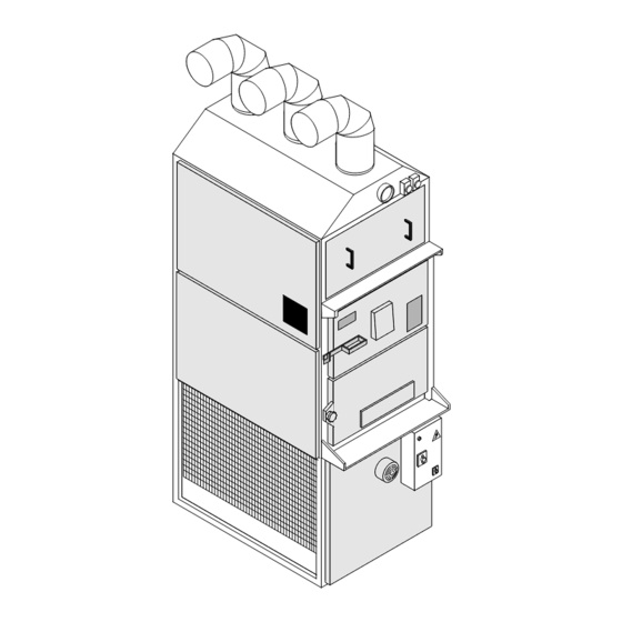
WARM AIR GENERATOR
MOD. F85
MOD. F120
MOD. F240
User guide
Assembling
FABBRI TERMOMECCANICA S.r.l.
Via Cangiotti, 10
61100 PESARO (PU)
Tel.0721/282537 Fax 0721/282970
www.fabbritermomeccanica.it
e-mail: info@fabbritermomeccanica.it
YEAR OF MANUFACTURING
SERIAL NUMBER
Text Version
11-09
Advertisement
Table of Contents

Summary of Contents for Fabbri Termomeccanica F85
- Page 1 Technical guidebook User guide Assembling Maintenance WARM AIR GENERATOR MOD. F85 YEAR OF MANUFACTURING MOD. F120 SERIAL NUMBER MOD. F240 Text Version 11-09 FABBRI TERMOMECCANICA S.r.l. Via Cangiotti, 10 61100 PESARO (PU) Tel.0721/282537 Fax 0721/282970 www.fabbritermomeccanica.it e-mail: info@fabbritermomeccanica.it...
- Page 2 LEGEND This symbol indicates danger, and will be used every time the operator’s safety is involved. This symbol indicates caution and is used to draw attention on very important operations needed for the proper and long-lasting use of the. This symbol represents an environmental note, and draws attention on rules to follow for the environment’s preservation.
- Page 3 For any repair operations, always refer to a manufacturer-authorized assistance centre, and ask for original spare parts. Disregarding any of the above might compromise the machine’s safety. MODEL SERIAL NUMBER YEAR OF MANUFACTURING FABBRI TERMOMECCANICA S.r.l. Via Cangiotti, 10 61100 PESARO Tel.0721/282537 Fax 0721/282970 www.fabbritermomeccanica.it e-mail: info@fabbritermomeccanica.it...
-
Page 4: Table Of Contents
2.6 MAINTENANCE SPACE ............................13 2.7 ELECTRIC PLUG-IN ............................... 14 3 OPERATION ..........................16 3.1 PRELIMINARY CONTROLS (version F85 CV - F120 - F240) ................16 3.2 STARTUP ................................... 16 3.2.1 STARTUP (summer) ............................... 16 3.3 TWIN THERMOSTAT FUNCTIONING ......................... 17 3.3.1 FAN FUNCTIONING ............................. -
Page 5: Technical Specifications
1 TECNICAL SPECIFICATIONS 1.1 MACHINE DESCRIPTION This machine is a warm air generator which operates with solid fuel. The framework is made up of a square profiled steel chassis and panels in galvanized polished steel. On the chassis’ lower part are located the vents for the air to be heated, which push the air inside the heat exchanger. -
Page 6: Work Station
EN 563 Machine safety – contact surface temperature. Ergonomic data to establish temperature va- lues limits for heated surfaces. (june 1994). UNI 8364 Heating systems – checkup and maintenance. Directive CEE 73-23 (Directive regarding low tension). EN 60204-1 Machine safety – electric equipment Part 1 general requirements. - 1992 (revision of EN 60204-1). -
Page 7: Models
MOD. F350 MOD. F55 S.V. MOD. F240 MOD. F55 C.V. MOD. F85 S.V. MOD. F85 C.V. 1.6 IDENTIFICATION When contacting the manufacturer, always provide the machine’s serial number and year of manufacturing, found on the plate affixed on the right hand side (see fig.3). -
Page 8: Encumbrance
1.6 IDENTIFICATION FIG.4 MODELS F55 S.V. F55 C.V. F85 S.V. F85 C.V. F120 F240 F350 1100 1220 A (mm) 1560 1750 1750 1980 1980 2200 2500 3000 B (mm) 1900 2100 2100 2400 2400 2600 3000 3400 B1 (mm) 1150... -
Page 9: Technical Specifications
1.9 TECHNICAL SPECIFICATIONS MODELS F120 F240 F350 DATA Fuel WOOD - CHIPPINGS – TURF Furnace power (Kcal/h) 29900 69000 99500 150000 300000 437000 (KW) Effective convention- (Kcal/h) 25000 55000 80000 120000 240000 350000 al power (KW) Air intake (m 3 /h) 2200 3500 6300... -
Page 10: Installation
2 INSTALLATION WARNING! The generator’s installation must be performed in observation of the current laws and technical rules, and its design must be performed by a freelance professional with regular profession registration HEATING SYSTEM DESIGN AND INSTALLATION Law n. 46, 5th May 1990. “Rules for systems safety”. -
Page 11: Transport
INSTALLATION RULES FOR THE ELECTRIC SYSTEM’S SAFETY. Law n. 186, 1st March 1968. “Rules for producing and installing electrical and electronic systems, materials, and machines.” Italian Electro-technical Committee Rule 64-8. Electric systems operating at a nominal tension non above 1000 V A/C and 1500 V D/C 2.1 TRANSPORT The machine can be transported via truck, ship, train, and plane. -
Page 12: Environmental Specifications
Install the various tracts of the warm air generator’s flue (pos.4, 5, 6 fig.7a-7b-7c). WARNING! You must install at least one special pipe T-shaped element in the flue (pos.7 fig.7a-7b-7c), which helps in cleaning operations. FIG.7a MODELS F85 WITH FUMES VENT 2÷3 mt. PROTECTION DURING PLUGGING OF THE ELECTRIC POWER CABLE... - Page 13 FIG.7b MODELS F85 WITHOUT FUMES VENT 2÷3 mt. PROTECTION DURING PLUGGING OF THE ELECTRIC POWER CABLE WARNING! The initial vertical section of the flue should never measure more than 2 or 3 meters in length (pos. 5 fig.7a-7b-7c) before applying the T-shaped tract (pos.7 fig.7a-7b-7c).
-
Page 14: Maintenance Space
That damage in not covered by the warranty. IMPORTANT: verify that the power cable is the right size. Turn the switch on the 0 position in the F85 CV-F120-F240 models (pos. A fig.11), in the F85 (pos. A fig.11B). - Page 15 FIG.9 FIG.10 In the F85 SV model, proceed as follows: - Turn on the general; - Press the “FAN” button to start up the vents (fig.10b); - Make sure the vents’ orientation in correct (refer to the arrows on the fans)
-
Page 16: Operation
3 OPERATION In the F85CV - F120- F240 models 3.1 PRELIMINARY CONTROLS WARNING! Before starting up the machine make sure that: - The power grid’s general switch is turned off (pos. OFF). - The machine’s general switch is turned on 0 (pos.A fig. 11). - All installation and assembling has been performed correctly, especially during FIG.11... -
Page 17: Twin Thermostat Functioning
3.3 TWIN THERMOSTAT OPERATION The thermostat’s sensor is placed on the suction vent. It can start and stop the ventilation system (FAN function), and regulates the overheating alarm mechanism (LIMIT function) when it is available. 3.3.1 FAN FUNCTION When the ambient temperature near the sensor reaches the value set on the twin thermostat’s board (40°C), an electric contact in the thermostat will be closed, and the ventilation system will activate. -
Page 18: Preliminary Controls (Version F85 Sv)
Model F85 SV only. 3.1 PRELIMINARY CONTROLS WARNING! Before starting up the machine make sure that: The power grid’s general switch is turned off (pos. OFF). The machine’s general switch is turned on 0 (pos.1 fig. 11). All installation and assembling has been performed correctly, especially during orientation of the vents. -
Page 19: Startup (Summer)
To adjust combustion, regulate suction power in the lower door (pos.3 in fig.13). When temperature reaches 45°C, the air vents will activate automatically (pos.5 in fig.16), and they will automatically switch off as well when temperature drops below 41°C. The alarm’s thermostat is already set to activate at 90°C. 3.2 STARTUP (summer) IMPORTANT: to turn on cold air circulation, press the fumes vent button (pos.3 fig.16) in absence of combustion. -
Page 20: Operation
3.4 OPERATION The machine must only be loaded with fuel via the upper door (pos. 1 in fig.13). Fuel examples include: - Dry wood not treated with chemicals. - Wood chippings pressed in bundles. WARNING! Do not use powdered wood, nor liquid fuel, during startup and combustion. Removing ashes. -
Page 21: Ordinary Maintenance
4 ORDINARY MAINTENANCE FIG.18 4.1 PRELIMINARY CONTROLS WARNING! Before maintenance, make sure that: - The power grid’s general switch is turned off (pos. OFF). - The machine’s general switch in on 0 (Fig. 18), that a padlock is placed on the appropriate lock, and its keys given to the safety operator. -
Page 22: Wiping Off The Ash
4.2.1 WIPING OFF THE ASH Every time the machine is stopped, the ash on the bottom of the combustion chamber must be removed 4.2.2 CLEANING THE FLUE To proceed with cleaning you must: - Unplug suction (pos. A in fig. 19). - Unplug the flue from the suction (pos. -
Page 23: Replacing The Thermostat Probe (Version F85 Sv)
4.4 REPLACING THE THERMOSTAT PROBE (model F85 SV only) To replace the thermostat probe: - unscrew the probe holder (pos.A fig.21); - remove the probe holder and remove the central screw (pos.B fig.21) in the probe’s lodge; - unplug the probe’s lodge by unscrewing it (pos.C and pos.D fig.21);... -
Page 24: End Of Service
5 END OF SERVICE When the machine’s lifetime is up, you should: - remove all rubber parts (O-ring, gaskets, girds, etc...). - remove all recyclable plastic components (thermoplastic parts) and separate them from the unrecyclable ones (thermo-resistant parts). - remove all copper parts (cables). Dispose of the different materials according to your Country’s laws. -
Page 25: Spare Parts Catalogue
7 SPARE PARTS CATALOGUE HOW TO ORDER SPARE PARTS To order spare parts, the following specifications must be presented: - Machine type (model, serial number, year of manufacturing. - Spare part description. - Quantity needed. - Any indications the spare part might have engraved on a plate. N°... -
Page 26: Tav. 1 Spare Parts F85
TAV.1 SPARE PARTS F85... -
Page 27: Tav. 2 Spare Parts F120-240
TAV.2 SPARE PARTS F120-F240... -
Page 28: Tav. 3 Electric Plan F85-1Sv
ELECTRIC PLAN F85-1 WITHOUT FUMES VENT TAV.3... -
Page 29: Tav. 4 Electric Plan F85-2Sv
ELECTRIC PLAN F85-1 WITH FUMES VENT TAV.4... -
Page 30: Tav. 5 Electric Plan F85-1Cv
ELECTRIC PLAN F85-1 WITH FUMES VENT TAV.5... -
Page 31: Tav. 6 Electric Plan F85-2Cv
ELECTRIC PLAN F85-2 WITH FUMES VENT TAV.6... -
Page 32: Tav. 7 Electric Plan F120-1
ELECTRIC PLAN F120-1 TAV.7... -
Page 33: Tav. 8 Electric Plan F120-2
ELECTRIC PLAN F120-2 TAV.8... -
Page 34: Tav. 9 Electric Plan F240-1
ELECTRIC PLAN F240-1 TAV.9... -
Page 35: Tav. 10 Electric Plan F240-2
ELECTRIC PLAN F240-2 TAV.10...
Need help?
Do you have a question about the F85 and is the answer not in the manual?
Questions and answers