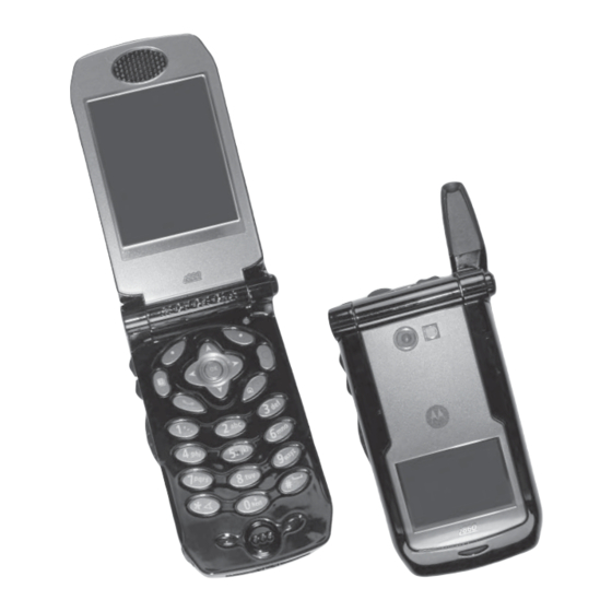
Motorola INTELLIGENCE EVERYWHERE I860 Field Service Manual
Iden digital multi-service, data-capable portable basic and field level test procedures
Hide thumbs
Also See for INTELLIGENCE EVERYWHERE I860:
- User manual (202 pages) ,
- Fact sheet (3 pages) ,
- Manual (155 pages)
Table of Contents
Advertisement
Quick Links
Advertisement
Table of Contents
Troubleshooting

Related Manuals for Motorola INTELLIGENCE EVERYWHERE I860


Summary of Contents for Motorola INTELLIGENCE EVERYWHERE I860
- Page 2 i860 Digital Multi-Service, Data-Capable Portable Field Service Manual Basic and Field Level Test Procedures July 8, 2004 68P80400P73-A...
- Page 3 Motorola’s prior written consent. Furthermore, the purchase of Motorola products shall not be deemed to grant either directly or by implication, estoppel, or otherwise, any license or rights under the copyrights, patents, or patent applications of Motorola, except for a nonexclusive license to use the Motorola product and the Motorola computer programs with the Motorola product.
-
Page 4: Safety And General Information
To maintain compliance with FCC RF exposure guidelines, if you wear a radio product on your body when transmitting, always place the radio product in a Motorola approved clip, holder, holster, case or body harness for this product. Use of non-Motorola-approved accessories may exceed FCC RF exposure guidelines. -
Page 5: Medical Devices
SAFETY AND GENERAL INFORMATION ALL MODELS WITH FCC ID AZ489FT5833 MEET THE GOVERNMENT'S REQUIREMENTS FOR EXPOSURE TO RADIO WAVES. Your wireless phone is a radio transmitter and receiver. It is designed and manufactured not to exceed the emission limits for exposure to radiofrequency (RF) energy set by the Federal Communications Commission of the U.S. -
Page 6: Operational Cautions
Operational Warnings For Vehicles Equipped with an Air Bag Do not place a portable radio product in the area over the air bag or in the air bag deployment area. Air bags inflate with great force. If a portable radio is placed in the air bag deployment area and the air bag inflates, the radio product may be propelled with great force and cause serious injury to occupants of the vehicle. - Page 7 SAFETY AND GENERAL INFORMATION • Use of a non-recommended attachment to a battery charger may result in a risk of fire, electric shock, or injury to persons. • Make sure the battery charger power cord is located so that it will not be stepped on, tripped over, or subjected to damage or stress.
-
Page 8: Model Information
MODEL INFORMATION This manual applies to the following iDEN i860 Digital Portable models: H73XAN6RR4AN 806-940 MHz, Multi-Service, Data-Capable Portable MODEL NUMBERING SYSTEM Typical Model Number: Position: Position 1 - Type of Unit H = Hand-Held Portable M = Mobile Product Positions 2 and 3 - Model Series 40 = i85s/i55sr/i50sx Products 41 = i90c Products... -
Page 9: Model Specifications
MODEL SPECIFICATIONS MODEL SPECIFICATIONS GENERAL FCC Designation: AZ489FT5833 Receiver Type: Operational Modes: Phone Private Group Circuit Data 800 MHz Band only: Packet Data Temperature Range: Operating –10°C to +60°C Storage (w/o battery) –40°C to +85°C Power Supply: Battery Type Lithium Ion Recommended Battery: SNN5704C... -
Page 10: Table Of Contents
CONTENTS SAFETY AND GENERAL INFORMATION ..MODEL INFORMATION ..... MODEL SPECIFICATIONS....CONTENTS . -
Page 11: Contents
CONTENTS Self-Test Errors............Self-Test Reset Errors. - Page 12 Connecting the Unit to the RSS Workstation ......Codeplug Repair Procedure..........Codeplug Troubleshooting .
- Page 13 CONTENTS Camera Test ..........APPENDIX A ORDERING REPLACEMENT PARTS AND KITS .
-
Page 14: Preface
The iDEN i860 Digital Multi-Service, Data-Capable Portable Field Service Manual contains the information necessary to identify and fix problems in the Motorola i860 Digital Portable. This unit is based on digital technology and is designed to operate on iDEN systems. -
Page 15: Conventions Used In This Manual
PREFACE: Conventions Used in This Manual Conventions Used in This Manual The following conventions are used throughout this manual: italics Used for emphasis and new terms bold Defines menu items, fields, and buttons Used for sample input and output code Related Publications The following publications are available separately: iDEN i860 Digital Multi-Service Data-Capable Phone User’s Guide... -
Page 16: Overview
CHAPTER 1 OVERVIEW To achieve a high spectrum efficiency, the i860 digital multi-service, data-capable portable uses a unique modulation technology and sophisticated voice-compression algorithm. The voice of the person speaking into the microphone is converted into a digital bit stream consisting of zeros (0) and ones (1). - Page 17 OVERVIEW: iDEN Digital Modulation Technology RL 0dBm Power (dB) Figure 1-1. Spectrum of iDEN Quad 16QAM Quadrature Phase Shift Keying (QPSK) is one of the most common modulation techniques for satellite communications. In QPSK, a digital data stream is taken two bits at a time to generate four possible phase states of the transmitted carrier.
-
Page 18: Iden Voice Compression Technology
algorithms and one digital-signal processor (DSP) to perform voice compression/decompression and RF modulation/demodulation. Base Station Control Channel Transmitting 6 of 6 slots continually. 15ms 15ms 15ms 15ms 15ms 15ms Receiver 4ms delayed Portable Unit When turned on, scans for control station, then transmits one slot every six slots. 15ms 15ms 15ms... -
Page 19: Calling Area Coverage
OVERVIEW: iDEN Voice Compression Technology (GPS) system. Each burst is numbered; the number is referred to as the slot number. All bursts occurring at a given time carry the same slot number. Inbound transmission bursts (sent from the unit) are offset 19 milliseconds from the outbound burst; the inbound burst begins 4 milliseconds after the end of the outbound burst (see Figure 1-2 on page 1-3). -
Page 20: Global Positioning System (Gps) Section
Global Positioning System (GPS) Section The U.S. Department of Defense (DoD) has built a 24-satellite constellation for the purpose of pinpointing locations anywhere on the planet. The satellites circle the earth every 12 hours, transmitting radio signals at a fixed frequency of 1575.42 MHz. The satellites share the 1575.42 MHz spectrum with each other through the use of CDMA modulation. - Page 21 OVERVIEW: SIM Cards To remove a SIM card (Figure 1-3): CAUTION: Do not touch the gold-colored area of the SIM card. 1. Power off the unit and remove the battery cover and battery. 2. Turn the unit face down so that the antenna is at the upper left corner. 3.
-
Page 22: Components, Icons, And Indicators
CHAPTER 2 COMPONENTS, ICONS, AND INDICATORS To conduct basic troubleshooting and maintenance of the i860 unit, you must become familiar with the components, display icons, and status indicators associated with the unit. Component Views Earpiece Full-sized Display Volume Controls Push-To-Talk (PTT) Button Audio Jack Audio Jack... -
Page 23: Display Icons
COMPONENTS, ICONS, AND INDICATORS: Display Icons Display Icons Icons for this unit provide information that is useful for troubleshooting and testing purposes. All features can be accessed through the main menu. When using a feature, the icon for that feature appears in the upper left corner of the display. Depending upon features and options chosen, the following icons can appear on the unit’s display. -
Page 24: Status Icons
Recent Calls: list of calls recent calls menu Call Setup menu Shortcuts Profiles: new profile form list of profiles Profiles menu Call Alert: list of call alerts Call Alerts menu Camera: Media Center: 2.2.2 Status Icons Status icons appear in the two rows at the top of the display. Some appear at all times. Others appear only when your phone is engaged in certain activities or when you have activated certain features. -
Page 25: Call Icons
COMPONENTS, ICONS, AND INDICATORS: Display Icons Ringer Off — your phone is set not to ring. Vibrate On — your phone is set vibrate. Speaker Off — Sets Direct Connect and Group Connect sound to come through the earpiece rather than through the speaker. Your phone does not ring for DC and GC calls if Alert Type is set to SILENT or Vibrate. -
Page 26: Contacts Type Icons
Information stored in Contacts is saved on your SIM card. If you move your SIM card to another SIM-based Motorola phone, you can access information stored in Contacts from that phone. Each number or address stored must be assigned a Contacts type. Contacts type icons that appear on... - Page 27 COMPONENTS, ICONS, AND INDICATORS: Display Icons This page intentionally left blank. 68P80400P73-O...
-
Page 28: Displays, Messages, And Alerts
Powering On Note: After Powering On the carrier logo will appear and next the T9 text input logo. Some carriers may not include T9 or other Motorola features in the power up display 2. No SIM Display Insert SIM Cancel... -
Page 29: Power-Down Sequence
DISPLAYS, MESSAGES, AND ALERTS: Power-Down Sequence Power-Down Sequence To power down the unit, press p for one second or more. Messages 3.3.1 Self-Test Errors The following table contains the list of self-test non-reset errors. These errors are displayed as SELF CHECK ERROR YXXXX (YXXXX represents the identifier for that error). -
Page 30: Service Messages
Target unit not authorized to Do not call unauthorized unit receive call Problem detected with the GPS Reboot unit. If problem persists, contact Motorola circuitry Unit does not have clear view of Make sure user is out in clear sky and stationary. If GPS satellites problem persists, reboot unit. -
Page 31: Alert Tones
DISPLAYS, MESSAGES, AND ALERTS: Alert Tones Alert Tones This unit can send alert tones to the earpiece, speaker, or external speaker. Press t to determine where some of the tones are sent. As shown in the following table, alert tones have specific frequencies and cadences/durations. They are grouped according to function;... - Page 32 Table 3-4. Alert Tones (Continued) Tone High Message Volume Set Spkr Spkr Net Alert Spkr One Minute Beep Phone Fast Busy Phone Redial Alert Spkr Spkr Phone Ring (U.S.) Spkr Spkr Phone Ring Back Private Call Spkr Spkr Received Reject Spkr Ringer Volume Set Spkr...
-
Page 33: Using The Optional Vibrate Function
DISPLAYS, MESSAGES, AND ALERTS: Using the Optional Vibrate Function Table 3-4. Alert Tones (Continued) Tone High Self-Test Fail Spkr Spkr Speaker Volume Set Spkr Spkr System Busy Spkr Talk Permit Spkr Talk Prohibit Spkr TOT Warning Spkr Valid Key Press Voice Mail Spkr Spkr... - Page 34 DISPLAYS, MESSAGES, AND ALERTS: Using the Optional Vibrate Function To set unit to vibrate for Direct Connect and Group Connect calls only: 1. From the main menu, select Settings > 2-Way Radio > Alert Type. 2. If Alert Type does not appear, from the main menu select Ring Tones. Make sure Vibrate All or Silent All is set to Off.
- Page 35 This page intentionally left blank.
-
Page 36: Preparing For Basic Level Testing
PREPARING FOR BASIC LEVEL TESTING Test Equipment The following equipment is useful when testing an i860 unit: a reference unit, a reference SIM card, and reference accessories. For a list of recommended test and programming equipment used to troubleshoot this unit, see Appendix A: Ordering Replacement Parts and Kits. 4.6.1 Reference Unit Use a reference unit (i860 unit known to be in good working order) to verify the accuracy of some tests. - Page 37 This page intentionally left blank.
-
Page 38: Basic Level Checks And Self Tests
CHAPTER 5 BASIC LEVEL CHECKS AND SELF TESTS Before you perform basic troubleshooting and self tests on an i860 unit, determine if any special conditions could affect testing and check the units for defective parts. There are five categories of basic tests: •... -
Page 39: Camera Test
BASIC LEVEL CHECKS AND SELF TESTS: Basic-Level Test Checklist Basic-Level Test Checklist Use the following checklist to ensure that all the necessary tests are performed and to provide a tracking mechanism in case the unit is sent to the next level of service. Check the appropriate box for each test performed and indicate whether or not the test was completed successfully. -
Page 40: Mechanical And Electrical Checks
Mechanical and Electrical Checks Before conducting more complex tests, clean and check the unit for any mechanical defects that might cause or contribute to the problem. The following tests constitute the mechanical and electrical consistency of the unit: • Shock and Pressure •... -
Page 41: Accessory Swap Test
BASIC LEVEL CHECKS AND SELF TESTS: Mechanical and Electrical Checks 5. Power on the unit, and verify that the test SIM card works with the unit. If the unit works, the customer’s SIM card is defective and should be replaced, or the problem is due to operator error, system, or carrier. -
Page 42: Battery Connections Test
5.5.4 Battery Connections Test Use this test to check the battery connections in the unit. The battery connections test time is approximately 5 minutes: 1. Remove the battery cover and battery from the unit. 2. Inspect the battery for physical damage. If damage is evident, replace the battery. -
Page 43: Voltage Recognition Test
BASIC LEVEL CHECKS AND SELF TESTS: Mechanical and Electrical Checks 7. Press RFRSH. The unit will respond with “Scanning for Satellites” or “Satellite Data Is Outdated, Continue?” depending upon whether the GPS Almanac is up-to-date or not. 8. If the unit responds with “Satellite Data is Outdated, Continue?” press YES, otherwise, no action is required. -
Page 44: Troubleshooting
4. If the image is defective, the camera may need to be replaced via a new flip assembly. 5. Repeat steps 1 to 3. 6. If the image is defective, the main display may need to be replaced via a new flip assembly. 7. -
Page 45: Programming Menu Settings Check
BASIC LEVEL CHECKS AND SELF TESTS: Self-Test Procedures 5.7.2 Programming Menu Settings Check Use this test to verify that the unit’s menu settings perform correctly. The settings check test time is approximately 10 minutes: Display/Info: The Display/Info menu controls how the keypad and display appear: •... - Page 46 • Auto Ans — sets your phone to automatically answer an incoming call after a specified number of rings. When this feature is on, the phone answers by connecting you to the caller; it does not send the call to voice mail, unless you are out of coverage or on the line. •...
- Page 47 BASIC LEVEL CHECKS AND SELF TESTS: Self-Test Procedures Scroll to Last Call. Press • PTT Picture — • AlertType — sets your phone to make no sound when you receive DC and GC calls. To set your phone to vibrate instead of making a sound when you receive DC and GC calls, even if you want your phone to ring for other features: From the main menu, select Settings >...
- Page 48 • Line2 — sets ringer volume for phone line 2. • Messages — sets the volume of message notifications. • Earpiece — sets the volume of sound coming out of the earpiece. • Speaker — sets the volume of sound coming out of the speaker. •...
- Page 49 BASIC LEVEL CHECKS AND SELF TESTS: Self-Test Procedures • GPS PIN — enables and disables your phone’s GPS PIN security feature. To turn the GPS Enabled security feature on or off: From the main menu, select Settings > Security > GPS PIN. Scroll to On or Off.
-
Page 50: Call Performance Test
• Return to Home — controls how long the recent calls list displays after calls. • Airplane Mode — User option to stop unit from receiving/transmitting radio frequency. Settings > Advanced > Airplane Mode > OK > Off. Settings > Advanced > Airplane Mode > OK > On. Settings >... - Page 51 This page intentionally left blank.
-
Page 52: Basic Level Test Modes And Procedures
CHAPTER 6 BASIC LEVEL TEST MODES AND PROCEDURES To complete basic testing of an i860 unit, you must enter a test mode to retrieve data from the unit, and perform the technician tests in the correct sequence with the appropriate equipment. Test procedures are listed in the order in which they should be implemented. -
Page 53: Display Screens
BASIC LEVEL TEST MODES AND PROCEDURES: Test Modes 6.1.2 Display Screens Display screens on this unit provide information that is useful for troubleshooting purposes. These displays appear only when the unit is placed in debug mode (see “Entering Debug Mode” on page 6-1). -
Page 54: Entering Test Mode
Table 6-1. Display Screens (Continued) Name IMEI/SIM ID Registr Log Err/Chan Codes Current Freq Dispatch IDs Band Info Bandmap Hardware Fatal Err/# Flags Resets Coin Cell CE Status 6.1.3 Entering Test Mode Use this procedure to access test mode. To enter test mode: 1. -
Page 55: Test Mode Test Procedures
BASIC LEVEL TEST MODES AND PROCEDURES: Test Mode Test Procedures 3. Press *. 4. Press Menu three times. 5. Press the left Scroll key. 6. Press Menu twice. 7. Press the left Scroll key. 8. Press Menu. You now are in test mode. To exit test mode, press the option key under Exit. -
Page 56: Esn And Imei Matching Test
9. Press the Start option key to begin the actual audio test in the TX On mode. 10. Talk into the microphone. The audio from the earpiece should sound clear. If there is a problem with the microphone or the earpiece, power down the unit and repeat the test. - Page 57 BASIC LEVEL TEST MODES AND PROCEDURES: Test Mode Test Procedures c. Press Select to view the Codeplug Version. The first half of the line displays the codeplug structure and default version; the second half displays the codeplug bandmap. d. Press Back to return to the Unit Info display, and then scroll down to highlight the CSD Ver choice.
- Page 58 e. Summary selection contains time and longitude/latitude expressed in degrees. Accuracy in meters is also displayed. GPS Version contains information about the custom Sirf software used in the unit. 13. Press Back to return to the Trace Mode display. 14. Scroll down to highlight IMEI/SIM ID, and then press OK to view the IMEI/SIM ID display. The IMEI is the global name assigned to the mobile station at manufacturing time and should correspond to the serial-number tag of the unit.
-
Page 59: Technician Test Procedures
BASIC LEVEL TEST MODES AND PROCEDURES: Technician Test Procedures 28. Scroll down to highlight Hardware, and then press OK to view the Hardware display. This screen displays RF Xtal (RF Crystal), a factory-tuned parameter that adjusts the output frequency; Xtal Offset (RF Crystal Warp offset), which is derived during frequency compensation;... -
Page 60: Connecting The Unit To The Rss Workstation
BASIC LEVEL TEST MODES AND PROCEDURES: Connecting the Unit to the RSS Workstation Connecting the Unit to the RSS Workstation Some technician tests enter programming information into the unit. To perform these tests, the unit must be correctly connected to the test equipment. Recommended equipment: data cable RS232 (NKN6560A) or USB data cable (NKN6559A), computer workstation with RSS installed. -
Page 61: Codeplug Repair Procedure
BASIC LEVEL TEST MODES AND PROCEDURES: Connecting the Unit to the RSS Workstation 6.5.1 Codeplug Repair Procedure If the codeplug is corrupted, the unit displays a SELF CHECK ERROR 0800 message. The procedure for repairing a corrupted codeplug is described in the RSS online Help System. Equipment Required: Computer workstation with RSS installed, data cable RS232 or USB, To access the codeplug Help topic in Windows: 1. -
Page 62: Preparing For Field Level Testing
• Ground the working surface of your service bench. If possible, use the Motorola Static Protection Assembly (P/N 0180386A82) to ground your service bench. This assembly contains a wrist strap, two ground cords, a table mat, and a floor mat. -
Page 63: Using Rss
Prior to touching any printed-circuit board, touch an electrical ground to remove any static charge that might have accumulated. Refer to Service and Repair Note SRN-F1052 for more information. This note is available through: Motorola Literature Distribution Center 2290 Hammond Drive Schaumburg, IL 60173... - Page 64 5.0 to 12.0 Vdc Power Supply To connect the unit to the R-2660: 1. Ensure the unit is powered off, and then turn on the R-2660. 2. Remove the battery cover and battery from the unit, and insert the reference SIM card. 3.
-
Page 65: Operating The R-2660
PREPARING FOR FIELD LEVEL TESTING: Operating the R-2660 10. Power up the subject unit. Refer to the R-2660 Digital Communications System Analyzer Operator’s Manual for more information on how to use this equipment. Operating the R-2660 Most of the technician tests performed with the R-2660 Communications System Analyzer require that the analyzer use the Initial Registration test mode. -
Page 66: Disassembling And Reassembling The Unit
Disassembling and Reassembling the Unit Motorola recommends the service technician follow a prescribed disassembly sequence to access specific items or components of the unit. This product is an efficiently designed package that incorporates the physical overlap and integration of some modular components. Refer to the Disassembly Sequence flowchart for a suggested path to reach specific components. -
Page 67: Battery Cover
PREPARING FOR FIELD LEVEL TESTING: Battery Cover Battery Cover 7.7.1 Remove: 1. Place thumb or fingernail against release latch (see Figure 7-2). 2. Push button down until cover releases and pull cover away. 3. Push cover up to release from top clips. 7.7.2 Install: 1. -
Page 68: Antenna
Antenna Required Tools: T-4 Torx bit, sharp scribe. 7.9.1 Remove: 1. Extend antenna whip fully. 2. Remove valence plug at base of antenna to expose T4 screw head (see Figure 7-3). 3. Loosen T-4 counterclockwise. Remove completely. 4. Hold unit stationary while pulling at antenna collar until antenna assembly releases. -
Page 69: Back Housing
PREPARING FOR FIELD LEVEL TESTING: Back Housing 7.10 Back Housing Required Tools: T-6 Torx bit, black stick. Preparation: Remove battery cover, extend antenna. Open audio jack seal and accessory connector seal. 7.10.1 Remove: 1. Remove four T-6 screws—one in the antenna tube channel. 2. -
Page 70: Coin Cell
7.11 Coin Cell Required Tools: Black stick. 7.11.1 Remove: 1. Locate coin cell at flex strip near speaker (see Figure 7-6). 2. Pull up coin cell flex strip carefully with stick. Do not crease or fold flex (see Figure 7-7). 3. -
Page 71: Main Board, Microphone Seal, And Keypad
PREPARING FOR FIELD LEVEL TESTING: Main Board, Microphone Seal, and Keypad 7.12 Main Board, Microphone Seal, and Keypad Required Tools: Black stick. 7.12.1 Remove: 1. Wedge black stick under 50-pin flex connector. Gently pry upwards along length until release (see Figure 7-9). 2. -
Page 72: Flip Assembly
(see Figure 7-17). 5. Once engaged, gently pull the tool/ mechanism while maintaining alignment of the tool line and MOTOROLA name. Adjust flip angle within 3 to 5 degrees to maintain alignment (see Figure 7-18). 6. Twist flip assembly slightly while prodding flex strip out through slot in front housing (see Figure 7-12). - Page 73 PREPARING FOR FIELD LEVEL TESTING: Flip Assembly Figure 7-14. Figure 7-16. 7-12 Figure 7-15. Figure 7-17. Figure 7-18. 68P80400P73-A...
- Page 74 4. Insert the mechanism/tool into the flip knuckle hole (see Figure 7-20). Maintain alignment of the tool’s line with the MOTOROLA name. 5. Push in the tool/mechanism until it stops then, rotate the tool clockwise approximately 9 degrees while pushing simultaneously (see Figure 7-21).
- Page 75 PREPARING FOR FIELD LEVEL TESTING: Flip Assembly 7-14 Figure 7-20. Figure 7-21. 68P80400P73-A...
-
Page 76: Exploded View And Parts List
7.14 Exploded View and Parts List This section contains the component parts list and exploded view for the i860 unit. 68P80400P73-A PREPARING FOR FIELD LEVEL TESTING: Exploded View and Parts List 7-15... -
Page 77: 7.14.1 Component Parts List
PREPARING FOR FIELD LEVEL TESTING: Exploded View and Parts List 7.14.1 Component Parts List Table 7-2. Component List Description Housing, Flip Assembly Hinge Cover, Flip Knuckle, Left Housing, Front Screw, Center Cap, Hinge Button, Right Cover, Hinge Button, Right Housing, Back Assembly Antenna, Retract. -
Page 78: 7.15.2 Exploded View
PREPARING FOR FIELD LEVEL TESTING: Exploded View and Parts List 7.15.2 Exploded View 10 11 12 7-17 68P80400P73-A... - Page 79 This page intentionally left blank.
-
Page 80: Field Level Test Modes And Procedures
CHAPTER 8 FIELD LEVEL TEST MODES AND PROCEDURES To perform field level testing on the i860 unit, you must enter a test mode to retrieve data from the unit, and perform the technician tests in the correct sequence with the appropriate equipment. NOTE: All tests should be performed in an RF interference-free environment. -
Page 81: Required Test Equipment
FIELD LEVEL TEST MODES AND PROCEDURES: Required Test Equipment The following tests are performed in test mode: • TX Power Test • BER Tests 800BER1 800BER2 800BER3 800BER4 900BER1 900BER2 900BER3 NOTE: The Power, MPX, and MOD test parameters are for factory use only and should not be adjusted by field service personnel. - Page 82 FIELD LEVEL TEST MODES AND PROCEDURES: Field-Level Test Checklist Table 8-1. Field-Level Test Checklist Done Technical Tests Pass Fail Registration/Call TX Power 800BER1 800BER2 800BER3 800BER4 900BER1 900BER2 900BER3 Power-Up Keypad Audio Reset Reset Log GPS Receiver Camera Test 68P80400P73-A...
-
Page 83: Registration/Call Test
Registering failures. (Use a reference unit to get a baseline.) Note: For 900 MHz verification, please perform the BER Test. May require ordering additional option for test. Contact Motorola Customer Service (see Appendix A). Set up the R-2660 for iDEN Mobile operation, and connect the unit to the RF IN/OUT connector. -
Page 84: Sqe Test
SQE Test Use this test on a unit having any of the following symptoms: No service failures or poor SQE/ RSSI (poor performance in known good coverage area). Set up the R-2660 for iDEN Mobile operation, and connect the unit to the RF IN/OUT connector. -
Page 85: Tx Power Test
FIELD LEVEL TEST MODES AND PROCEDURES: TX Power Test TX Power Test Use this test on a unit on a unit having bad transmission (TX) or intermittent service failures. (This is a transmitter test only.) Set up the R-2660 for Spectrum Analyzer display, and connect the unit to the RF IN/OUT connector. -
Page 86: Ber Test
BER Test Use this test on a unit having any of the following symptoms: resets (RAAAA Type), No Service failures. Set up the R-2660 for iDEN BER Test, and connect the unit to the RF IN/OUT connector. Connect the battery eliminator to the unit. -
Page 87: Power-Up Test
FIELD LEVEL TEST MODES AND PROCEDURES: Power-Up Test Power-Up Test Use this test to check power-up. Symptoms: dead battery, short battery life, or unit does not power Try to power up the unit. Pass Verify that the display pixels light up. Pass Check the battery-level... -
Page 88: Keypad Test
Keypad Test Use this test to check the operation of the unit’s keypads and display. Symptoms: unit locked, or stuck key Power up the unit. Enter the Model Assembly (MA) Test Mode. Verify that all the display tests complete correctly. Pass Proceed to the MA Test... -
Page 89: Audio Test
FIELD LEVEL TEST MODES AND PROCEDURES: Audio Test 8.10 Audio Test Use this test to check the audio portion of the unit. Set up the R-2660 for iDEN Mobile operation, and connect the unit to the RF IN/OUT connector. Place an interconnect call. -
Page 90: Reset Test
8.11 Reset Test Use this test on a unit having any of the following symptoms: unit resets, or unit powers off and then Set up the R-2660 for iDEN Mobile operation, and connect the unit to the RF IN/OUT connector. Power up the unit. -
Page 91: Reset Log Test
FIELD LEVEL TEST MODES AND PROCEDURES: Reset Log Test 8.12 Reset Log Test Use this test to check the reset log in the unit. To perform the reset log test: 1. Power on the unit and wait until registration is complete. 2. -
Page 92: 8.13 Model Assembly (Ma) Test Mode Test
8.13 Model Assembly (MA) Test Mode Test Model Assembly Test Mode is an embedded series of operational tests of the unit's user interface and functional features. Motorola iDEN recommends MA Test Mode be performed after any servicing of the unit. - Page 93 FIELD LEVEL TEST MODES AND PROCEDURES: Model Assembly (MA) Test Mode Test 8.13 Model Assembly (MA) Test Mode Test (Continued) 8-14 68P80400P73-A...
-
Page 94: Gps Receiver
8.14 GPS Receiver Use this test on a unit to check functionality of the GPS. Find an open sky area. Turn unit Activate Phone returns location coordinates 68P80400P73-A FIELD LEVEL TEST MODES AND PROCEDURES: GPS Receiver Obtain reference receiver. Location coordinates match reference... - Page 95 FIELD LEVEL TEST MODES AND PROCEDURES: Camera Test 8.15 Camera Test Use this test to check camera module. Symptoms: Bad view finder (noise, poor color, synchronization error). Power up the unit. Enter the Model Assembly (MA) Test Mode. Verify that the viewfinder shows the captured image correctly.
-
Page 96: And Kits
ORDERING REPLACEMENT PARTS AND KITS Parts should be replaced with identical replacement parts. Replacement parts and kits for i860 units can be ordered directly from the Motorola Accessories and Aftermarket Division (AAD) at 1-800-422-4210 and listen to the prompts; or FAX 800-622-6210. -
Page 97: Replacement Kits
Replacement Kits When ordering replacement kits, the complete kit number should be included. If the correct number cannot be located, call Motorola Parts Identification at 1-800-422-4210. Refer to the exploded view and parts list in Chapter 7. Table A-2. i860 Replacement Kits... - Page 98 UK Plug Aus/NZ Plug Korean Plug Escutcheon Labels: Label, i860 Escutcheon - Korea Label, i860 Escutcheon - Motorola Label, i860 Escutcheon - EZENFREE Label, i860 Escutcheon - Nextel Label, i860 Escutcheon - GRID Label, i860 Escutcheon - Nextel International Label, i860 Escutcheon - Avantel...
-
Page 99: Recommended Test Equipment And Tools
Torx Bit, T-6 Torx Driver, calibrated Wrist Strap, Static ground Kit Number NNTN5486A NNTN5804A NNTN5805A NNTN5481A NNTN5483A Part Number NNTN5589A SLN7223A NNTN5175A Contact Motorola Motorola R-2660 NKN6560A NKN6559A Keithly 2001 or eq. 6664616H01 6664617H01 6680384A33 S1348D 6680343A16 NTN9208 Commercially available Commercially available... -
Page 100: Recommended Programming Equipment
Recommended Programming Equipment The following tables list the programming equipment and software recommended for troubleshooting i860 units at the field level of service. Table A-4. Recommended Programming Equipment Name Cable, Data, RS232 Cable, Data, USB Cable, Data (2.5mm) Cable, Data (for GPS interface) Computer, IBM PC-Compatible (RSS Workstation) Table A-5. - Page 101 This page intentionally left blank.
-
Page 102: Index
INDEX accessories reference 4-1 Accessory Swap test 5-4 alert tones 3-4 allocating time 1-2 altering RF signals 1-1, 1-2 antenna considerations 5-1 Audio Loopback test 6-4 Audio test 8-10 bands primary 6-3 secondary 6-3 base station 1-4 basic test procedures 6-1 basic-level test checklist 5-2 Battery Connections test 5-5... - Page 103 INDEX Keypad test 8-9 kits ordering A-1 replacement A-2 Lockup test 5-4 mechanical checks Accessory Swap 5-4 Audio Loopback 6-4 basic 5-1 Battery Connections 5-5 Lockup 5-4 Voltage Recognition 5-6 menu settings 5-8 messages, service 3-3 mode debug 6-1 dispatch 1-4 Initial Registration 7-4 interconnect 1-4 test 6-1, 6-3, 8-1...
- Page 104 replacement parts domestic orders A-1 international orders A-1 reset condition 5-1 reset errors 3-2 Reset Log test 8-12 Reset test 8-11 allocation 1-2 altering signals 1-1, 1-2 checking cables 7-1 transmission bursts 1-3 QuickComm feature 6-9 See Radio Service Software using 7-2 version A-5 workstation A-5...
- Page 105 INDEX See also self-test procedures See also technician tests SQE 8-5 TX Power 8-6 Voltage Recognition 5-6 time allocation 1-2 Time Division Multiple Access overview 1-2 RF signal time allocation 1-2 tones, alert 3-4 tools, recommended A-4 transmission bursts 1-3 troubleshooting 5-7, 6-10 TX Power test 8-6 unit...
- Page 106 © 2004 by Motorola, Inc. 8000 W. Sunrise Blvd. Ft. Lauderdale, FL 33322 Printed in U.S.A. 6/04. All Rights Reserved. Motorola Confidential Proprietary @6880400P73@ 68P80400P73-A...