Table of Contents
Advertisement
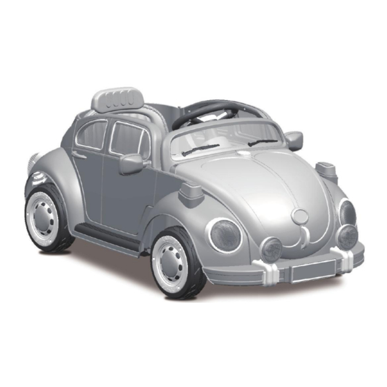
CHILDREN'S ELECTRIC RIDE-ON
With remote control function
Styles and colours may vary.
Made in China.
The owner's manual contains important safety information as well as assembly, use and
maintenance instructions.
The Ride-On car must be assembled by an adult who has read and understands the
instructions in this manual.
Keep the package away from children and dispose of properly before use.
Keep this manual for future reference.
Owner's Manual
with Assembly Instructions
Advertisement
Table of Contents

Summary of Contents for Maplin N74DG
- Page 1 CHILDREN'S ELECTRIC RIDE-ON With remote control function Owner's Manual with Assembly Instructions Styles and colours may vary. Made in China. The owner's manual contains important safety information as well as assembly, use and maintenance instructions. The Ride-On car must be assembled by an adult who has read and understands the instructions in this manual.
- Page 2 About Your New Ride-On 1 Details on the purchase of your new Ride-On car. This Ride-On car will provide your child with many hours of riding of enjoyment. To help assure you and your child a safe experience, we ask you to please read this manual carefully, and keep it for future reference.
-
Page 3: Parts List
Parts List 2 Q'ty (pcs) PART REMARKS PART NAME Gear box Driving wheel • 12 washer • 10 locknut Bushing Normal wheel Motor hood Vehicle body Rear axle Steering column Headlight View mirror Front axle One pair Seat M5x12 machine screw Placed on the vehicle body Steering wheel M5x35 machine screw... -
Page 4: Parts Diagram
Parts Diagram 3 NOTE: Some parts shown are assembled on both sides of vehicle... - Page 5 Attach the Side Support 4 WARNING! FOR THE SAFETY OF YOUR CHILD, PLEASE READ ALL WARNINGS AND ASSEMBLY/USE INSTRUCTIONS. KEEP THIS GUIDE FOR FUTURE REFERENCE. • ADULT ASSEMBLY REQUIRED. The product contains small parts, which are for adult assembly only. Keep children away when assembling. •...
- Page 6 Attach the Rear Axle 5 • 4x12 flat screws, part A 1. Fit the front axle to the vehicle body. 2. Tighten four Ø4x12 screws flat head screwis, part A to secure it. 3. Repeat for the other side. Remove all the parts from the rear axle.
- Page 7 Attach the Rear Wheels 6 Rear axle Tools required: Spanner 1. Slide the gearbox onto the rear axle (Left Side). 2. Slide the driving wheel onto the rear axle. And make the driving wheel line up with the gearbox. 3.
- Page 8 Attach the Rear Wheels 7 Rear axle 1. Slide the gearbox onto the rear axle (Left Side). "R" labelled gear box should be fit to the "R" side of vehicle body; "L" labeled gear box should be fit to "L" side of vehicle body. 2.
- Page 9 Attach the Front (Normal) Wheels 8 Front axle Tools required: Spanner 1. Slide a Ø12 washer onto the front axle. 2. Slide the bushing (ring end first) onto the front axle. 3. Slide the normal wheel (with wheel hubcap) onto the rear axle. and keep the normal wheel lined up with theBushing.
- Page 10 Attach the Steering Column 9 Hole in the front axle linkage Steering Gear Box Turn the vehicle body on its side. 1. Attach the R/C driver to the steering gearbox, then make it match with steering 1. Slide a Ø10 washer onto the steering column and the straight end or the gearbox.
- Page 11 and column up through the hole. Insert the R/C diver through the vehicle body from end of steering and out through the the hole in the steering gearbox from the bottom side, and out through the hole. 4. Insert the bent end of steering column through the hole in the front axle in the dash linkage.
-
Page 12: Attach The & Steering Wheel
Attach the & Steering Wheel 10 Turn the vehicle body upright. 1. Fit the headlight to the vehicle body, and push until you hear it click. 2. Repeat for the other headlight. Remove the M5x35 machine screw and • 5 nut from the steering wheel. -
Page 13: Connect The Power Supply
Connect the Power Supply 11 • 4x12 flat screws, part A Battery 1. Fit the motor hood on the motor. 2. Tighten four Ø4x12 flat head screws, part A to secure it. 1. Fit the motor hood on the motor. 2. - Page 14 Attach the Motor Hood 12 Vehicle connector Fuse box Battery Motor connector Red fuse connector 1. Plug the Vehicle Connector into the Motor Connector on body as shown above. 2. Plug the Red fuse connector into the terminal on battery. 1.
-
Page 15: Attach The Seat
Attach the Seat 13 1. Insert the rear view mirror into the slots of the rear view mirror bracket located on the door. 2. Insert a M5x20 machine screw through the top of the hole in the rear view mirror and rear mirror bracket (a nut inside the rear mirror bracket). -
Page 16: Attach The Rear View Mirrors
Attach the Rear View Mirrors 14 Remove the M5X12 machine screws *2 from the vehicle body. 1. Fit the tabs at back of the seat to the holes in the vehicle body. 2. Tighten two M5x12 machine screws with a screwdriver. -
Page 17: Rules For Safe Riding
Safety 15 WARNING! PREVENT INJURIES AND DEATHS: • NEVER LEAVE CHILD UNATTENDED. DIRECT ADULT SUPERVISION IS REQUIRED. Always keep child in view when child is in vehicle. • This toy should be used with caution since skill is required to avoid falls or collisions causing injury to the user or third parties. - Page 18 Use Your Ride-on 16 IMPORTANT! Always stop vehicle when changing the speed or direction to avoid damage the gears and motor. 1. Power Switch: Turns the vehicle on and off. 2. Shift Lever: Changes the direction the vehicle moves from forward to reverse. ●...
-
Page 19: Battery Information
Use the Remote Controller 17 ADULT OPERATING REQUIRED LEFT JOY STICK INDICATOR LIGHT RIGHT JOY STICK ON-OFF SWITCH ASSEMBLY 1. Insert the antenna into the controller by tweak the antenna clock- wisely; 2. Lift the battery compartment door on the back of the controller and insert two AA(LR6) batteries. - Page 20 Charging 17 ONLY AN ADULT CAN CHARGE AND RECHARGE THE BATTERY! WARNING! • PREVENT FIRE AND ELECTRIC SHOCK: - Use the only rechargeable battery and charger supplied with your vehicle. NEVER substitute the battery or the charger with another brand. Using another battery or charger my cause a fire or explosion. - Do not use the battery or charger for any other product.
- Page 21 Charging 18 • If your ride-on with a the magnitude of voltage will tell Digital voltmeter(OPTIONAL), you how much power is remaining in the battery when you must recharge the battery. Make sure the vehicle is stop! BATTERY M A G N I T U D E O F BATTERY STATE The battery is full.
- Page 22 This product with CHARGING PROTECTION: When charging, all the functions will be cut off!
-
Page 23: Battery Replacement And Disposal
Fuse & Battery Replacement 19 Battery Replacement & Fuse 20 Fuse The battery features a thermal fuse with a rest fuse that will automatically trip and cut all power to the vehicle if the motor, electric system or battery is overloaded. The fuse will reset and power will be restored after the unit is turned OFF for five Minutes and then turned ON again. -
Page 24: Troubleshooting Guide
Troubleshooting Guide 20 Possible Cause Solution Problem Vehicle dose not run Battery low on power Recharge battery. Thermal fuse has tripped Reset fuse, see <Fuse> Check that the battery connectors are firmly plugged Battery connector or wires into each other. If wires are loose around the motor are loose .contact your distributor please. - Page 25 21 Maintaining • It is parents' responsibility to check main parts of the toy before using, Must regularly examine for potential hazard, such as the battery, charge,cable or cord, plug, screws are fastening enclosure of other parts and that in the event of such damage, the toy must not be until that damage had been properly removed.
- Page 26 Our products are suitable for ASTM F963; GB6675; EN71 and EN62115 standard.
Need help?
Do you have a question about the N74DG and is the answer not in the manual?
Questions and answers