Table of Contents
Advertisement
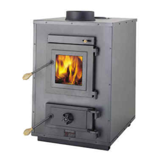
INSTALLATION AND OPERATION MANUAL
MODELS: 28-3500 , 50-SHW35 & 50-TRW35
WOOD ADD-ON FURNACE
Thank you for purchasing this product from a fine line of heating equipment.
Please read this manual before attempting to move or install your unit.
We wish you many years of safe heating pleasure with your new heating appliance.
Visit our web site at
www.heatredefined.com
for helpful information, frequently asked questions,
parts & accessory orders and more.
Please Note the Following Precautionary Statements:
England's Stove Works highly recommends the use of smoke detectors and Carbon
Monoxide detectors with any hearth product, including this unit. Follow all manufacturer's
instructions when using smoke and Carbon Monoxide detectors.
CAUTION:
This unit must be installed in accordance with these instructions and must comply with local
building and fire codes. Failure to do so could result in a chimney or house fire.
Keep children, furniture, fixtures and all combustible materials away from any heating appliance.
Maintain a minimum clearance of 18" (18 inches) from the flue pipe to any combustibles. Refer
to information in this manual and on the unit, and to all pipe manufacturers' instructions.
This unit is not mobile home approved.
Do not install this unit in a mobile home!
READ THESE INSTRUCTIONS CAREFULLY BEFORE INSTALLING THIS MODEL.
SAVE THESE INSTRUCTIONS FOR FUTURE REFERENCE.
INSTALLATION SHOULD BE PERFORMED BY A QUALIFIED INSTALLER.
NOTE: IF YOU HAVE A PROBLEM WITH THIS UNIT, DO NOT RETURN IT TO THE
DEALER. PLEASE CONTACT CUSTOMER SERVICE at (800) 245-6489.
FUEL: WOOD
HEATING CAPACITY: Approx. 3,000 SQ. FT (when fed into existing ductwork)
TESTED TO: UL 391, CSA-B366.1, ETLM 78.1
Rev: 4/2015
Advertisement
Table of Contents

Related Manuals for England’s Stove 28-3500

Summary of Contents for England’s Stove 28-3500
- Page 1 INSTALLATION AND OPERATION MANUAL MODELS: 28-3500 , 50-SHW35 & 50-TRW35 WOOD ADD-ON FURNACE Thank you for purchasing this product from a fine line of heating equipment. Please read this manual before attempting to move or install your unit. We wish you many years of safe heating pleasure with your new heating appliance.
- Page 2 A letter from our Technical Support department: Thank you for purchasing this fine product from England’s Stove Works! England's Stove Works was started, and is still owned by, a family that believes strongly in a "Do It Yourself" spirit – that’s one reason you found this product at your favorite “Do It Yourself”...
-
Page 3: Safety Notice
SAFETY NOTICE IF THIS UNIT IS NOT PROPERLY INSTALLED, A HOUSE FIRE MAY RESULT. FOR YOUR SAFETY AND PROTECTION, FOLLOW ALL OF THE INSTALLATION INSTRUCTIONS. INSTALLATION SHOULD BE PERFORMED BY A QUALIFIED INSTALLER. CONTACT YOUR LOCAL BUILDING OR FIRE OFFICIALS FOR RESTRICTIONS AND INSTALLATION INSPECTIONS REQUIRED IN YOUR AREA. - Page 4 C: Installation of a New Flue System 1. Masonry Flue: If you are considering a masonry flue (see Figure 1), you should contact your local building officials for the proper procedures required in the construction. We recommend that you consult with and have your flue built by a licensed, bonded contractor.
-
Page 5: Installation
INSTALLATION Venting Introduction Venting Guidelines This wood stove operates on a • ALWAYS install vent pipe in strict natural draft system, in which the chimney adherence to the instructions and system pulls air through the stove. This unit clearances included with your must be installed in accordance with the venting system. - Page 6 Installation Diagrams and Thermostat Wiring This appliance requires a masonry or pre-manufactured chimney listed to UL103HT, sized correctly. 18” Min. 18” Min. 18” Min. Figure 2 – Installation into a HT Pipe Flue System. LEFT – Through the Roof RIGHT – Through the Wall IMPORTANT NOTE: Do NOT connect this furnace to an external thermostat.
-
Page 7: Section Ii: Floor And Wall Protection
SECTION II: FLOOR AND WALL PROTECTION A. Floor Protection There is no protection required if your floor is constructed of a noncombustible material such as concrete. If your floor is constructed of a combustible material such as hardwood, carpet or linoleum some type of floor protection will be required. -
Page 8: Section Iv: The Function Of The Add-On Furnace
Chimney Connector Pipe This black pipe must be 6” (6 inches) in diameter and a 24-gauge or heavier pipe. Do not use aluminum or galvanized steel, as they cannot withstand the high temperatures of a wood fire. Do not use single wall pipe as a chimney. -
Page 9: Section V: Hot Air Hook-Up (See Fig. 3)
SECTION V: HOT AIR HOOK-UP (See Fig. 3) NOTE: The warm air supply-duct system should be constructed of materials with a minimum temperature rating of 250 deg. F. Also, the plenums installed to the furnaces are to be constructed of metal. NOTE: The hot air supply outlet of this supplementary furnace should not be connected to the cold-air return inlet of the central furnace, since a possibility exists that components of the central furnace could overheat in... -
Page 10: Section Vii: Operating Instructions
B. Thermostat Installation The thermostat, blower and power cord are all prewired (see Figure 4 for thermostat instructions); however, the thermostat must be connected to the furnace after installation of the blower. Do this by inserting the probe portion into the stove (remove the cover first, to reveal the mounting plate) and fastening the thermostat to the unit with the four screws that are mounted on the furnace. - Page 11 Notice: The surface of your new furnace and the connector pipe may smoke for a short time, and this is no cause for alarm. This is called “cooking out,” and it is advisable to open doors and windows in your dwelling during the first two hours (approximately) of operation.
- Page 12 Practical Tips for Building a Fire Once your wood-burning appliance is properly installed, building an effective fire requires good firewood (using the right wood in the right amount) and good fire building practices. The following practical steps will help you obtain the best efficiency from your wood stove or fireplace.
- Page 13 Safe Wood-burning Practices Once your wood-burning appliance is properly installed, follow these guidelines for safe operation: Keep all flammable household items—drapes, furniture, newspapers, and books—far away from the appliance. Start fires only with newspaper, dry kindling and all natural or organic fire starters.
- Page 14 may cause backpuffing into the room and ‘plugging’ of the chimney or the catalyst. Inadequate draft will cause the appliance to leak smoke into the room through appliance and chimney connector joints. An uncontrollable burn or excessive temperature indicates excessive draft.
- Page 15 5. Close the door completely, leaving both draft controls in the open position, and allow the furnace to burn in this manner for another 5 to 10 minutes. 6. Close both draft controls, then open both controls to your desired setting as described previously in “Building a Fire.”...
- Page 16 After emptying the ashes, the ash pan can be placed back into the unit and the small door closed. Never leave the ash door open or the unit unattended. G. Creosote Creosote – Formation and Need for Removal When wood is burned slowly, it produces tar and other organic vapors, which combine with expelled moisture to form creosote.
-
Page 17: Section Viii: Care And Maintenance
Refer to the list at the rear of this manual for part numbers. You may order parts by calling SECTION VIII: CARE AND MAINTENANCE (800) 516-3636 or logging on to (Unit must be cool and power unplugged www.heatredefined.com before performing any maintenance) A. -
Page 18: Section Ix: Chimney And Flue Pipe Maintenance
deactivates the blower when the temperature drops to 95 degrees Fahrenheit. By shutting off at 95 degrees, it allows the furnace to recover as the heat is extracted from the unit and forced through the duct system. We recommend that you leave the thermostat at the factory settings until the unit has been burned for at least 30 days. - Page 19 system. A typical example of this would be the flue system cooling down and the smoke not being able to exit the system, thereby building up in the chimney. The chimney will then “back puff” if there is wind blowing across the top of the flue system.
- Page 20 You may write your unit’s Manufacture Date and Serial Number in the blank spaces on this sample tag, for future reference. This sample tag also shows the safety info. such as UL testing standard, etc. for your local officials, or anyone else who may need reference information.
- Page 21 LIMITED 5 YEAR WARRANTY FROM THE DATE OF PURCHASE TO THE ORIGINAL OWNER The manufacturer extends the following warranties: Five Year Period: 1. Carbon steel and welded seams in the firebox are covered for 5 years against splitting. 2. The cast iron door, hasp and hinges are covered for 5 years against cracking. One Year Period: 3.
- Page 22 ADD-ON FURNACE PARTS / OPTIONS LIST (Check your model for paint color, trim color, etc. if ordering a replacement for an original part). AC-G9 GLASS (9” X 9”), with Gasket AC-GGK GLASS GASKET KIT (gasket only, no glass) AC-MBSP BLACK SPRAY PAINT AC-1339 THERMOSTAT AC-DGKC...
-
Page 23: Dealer Information
WARRANTY REGISTRATION for England’s Stove Works Purchased by (Name) ______________________________________________ Address _________________________________________________________ City ________________________ State __________ Zip _________________ Telephone _______________________________________________________ Email Address ___________________________________________________ DEALER INFORMATION Purchased From (Dealer) ___________________________________________ Address _________________________________________________________ City ________________________ State __________ Zip _________________ UNIT INFORMATION (Please be sure to refer to sticker on back of manual or box to complete this section) Model Number _____________________ Purchase Date _________________ Purchase Price ____________________ Serial Number _____________________ Mfg.
Need help?
Do you have a question about the 28-3500 and is the answer not in the manual?
Questions and answers
What is the minimum venting flue height for the 28-3500. Thank you.
The minimum venting flue height for England’s Stove model 28-3500 must comply with the 10-3-2 rule: the chimney must terminate at least 3 feet above the point where its centerline passes through the roof and at least 2 feet above any part of the dwelling within a 10-foot radius.
This answer is automatically generated