MTD 607 Operator's Manual
Auto drive
Hide thumbs
Also See for 607:
- Operator's manual (48 pages) ,
- Owner's manual (38 pages) ,
- Operator's manual (48 pages)
Table of Contents
Advertisement
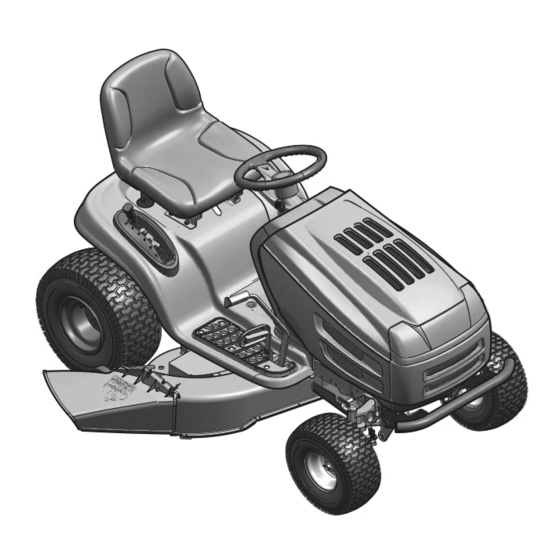
Operator's Manual
Auto Drive
Lawn Tractors
Models 607 & 608
IMPORTANT: Read safety rules and instructions carefully before operating equipment.
Warning:
This unit is equipped with an internal combustion engine and should not be used on or near any unimproved forest-covered,
brush-covered or grass-covered land unless the engine's exhaust system is equipped with a spark arrester meeting applicable local or state
laws (if any). If a spark arrester is used, it should be maintained in effective working order by the operator. In the State of California the above
is required by law (Section 4442 of the California Public Resources Code). Other states may have similar laws. Federal laws apply on federal
lands. A spark arrester for the muffler is available through your nearest engine authorized service dealer or contact the service department,
P.O. Box 361131 Cleveland, Ohio 44136-0019.
PRINTED IN U.S.A.
FORM NO. 770-10130G.fm
(11/2003)
Advertisement
Table of Contents

Related Manuals for MTD 607


Summary of Contents for MTD 607
- Page 1 Operator’s Manual Auto Drive Lawn Tractors Models 607 & 608 IMPORTANT: Read safety rules and instructions carefully before operating equipment. Warning: This unit is equipped with an internal combustion engine and should not be used on or near any unimproved forest-covered, brush-covered or grass-covered land unless the engine’s exhaust system is equipped with a spark arrester meeting applicable local or state...
-
Page 2: Finding Model Number
This information will be necessary to use the manufacturer’s web site and/or help from the Customer Support Department or an authorized service dealer. Copy the model number here: Copy the serial number here: MTD LLC P. O. BOX 361131 CLEVELAND,OH 44136 330-220-4683 www.mtdproducts.com... -
Page 3: Section 1: Important Safe Operation Practices
SECTION 1: IMPORTANT SAFE OPERATION PRACTICES WARNING: This symbol points out important safety instructions which, if not followed, could endanger the personal safety and/or property of yourself and others. Read and follow all instructions in this manual before attempting to operate this machine. Failure to comply with these instructions may result in personal injury. - Page 4 27. Use only accessories and attachments approved for this Do not tow heavy pull behind attachments (e.g. loaded machine by the machine manufacturer. Read, dump cart, lawn roller, etc.) on slopes greater than 5 understand and follow all instructions provided with the degrees.
-
Page 5: Your Responsibility
Never fill containers inside a vehicle or on a truck serviced professionally by your Troy-Bilt dealer. or trailer bed with a plastic liner. Always place Check brake operation frequently as it is subjected to containers on the ground away from your vehicle wear during normal operation. -
Page 6: Section 2: Slope Gauge
SECTION 2: SLOPE GAUGE... -
Page 7: Section 3: Tractor Set-Up
SECTION 3: TRACTOR SET-UP NOTE: This manual covers specifications of several models. Please follow instructions and parts numbers pertaining to your tractor only. Attaching the Battery Cables NOTE: The positive battery terminal is marked Pos. (+). The negative battery terminal is marked Neg. (–). 1. -
Page 8: Attaching The Seat
Attaching The Seat Seat styles vary by tractor model and there are three Standard Adjustment different styles available: • Standard Adjustment Hex Screws • Quick Adjustment & • Knob Adjustment Refer to Figure 3 to identify your tractor’s seat style and follow applicable instructions below. -
Page 9: Gas And Oil Fill-Up
Gas and Oil Fill-Up The gasoline tank is located under the hood and depending on the model of tractor, has a capacity of either two or three gallons. Do not overfill. WARNING: Use extreme care when handling gasoline. Gasoline is extremely flammable and the vapors are explosive. -
Page 10: Section 4: Operation
SECTION 4: OPERATION Know the Controls Read this owner’s manual and safety rules before operating your lawn mower. Compare figure below with your lawn tractor to learn about the loction and purpose of various controls and adjustments. Save this manual for future reference. - Page 11 Throttle Control Lever Choke The throttle control lever controls the speed of the engine. When set in a (Model only) given position, the throttle will maintain a uniform engine speed. Fast Choke Control Moving the throttle lever all the way forward activates the engine’s choke control.
- Page 12 Ignition Switch On/Lights Ignition switch is activated to start the engine. Insert key into the ignition switch and turn clockwise to the START position. Release the key into the ON position once engine has fired. Never leave a running machine unattended. Always WARNING: disengage PTO, move shift lever into neutral position, set parking brake, stop engine and remove key to prevent unintended starting.
-
Page 13: Safety Interlock Switches
Cruise Control Button The cruise control feature should only be utilized while traveling in the forward direction. To engage the cruise control, follow these steps: 1. Place shift lever in FORWARD position, then slowly depress the drive pedal until desired speed is achieved. 2. - Page 14 Starting the Engine NOTE: Refer to the TRACTOR SET-UP on page 7 manual for gasoline and oil fill-up instructions. IMPORTANT 1. Insert the tractor key into the ignition switch. 2. Disengage the PTO (Blade Engage) lever/knob. 3. Engage the tractor’s parking brake. 4.
- Page 15 • For best results it is recommended that the first two laps be cut with the discharge thrown towards the center. After the first two laps, reverse the direction to throw the discharge to the outside for the balance of cutting. This will give a better appearance to the lawn.
-
Page 16: Section 5: Making Adjustments
SECTION 5: MAKING ADJUSTMENTS WARNING: Never attempt to make any adjustments while the engine is running, except where specified in the operator’s manual.Disconnect spark plug wire(s) and ground against the engine before performing any adjustments, repairs or maintenance. Seat WARNING: Before operating this machine, Hex Screws make sure the seat is engaged in the seat stop,... -
Page 17: Leveling The Deck
Front tire toe-in can be measured as follows: 1. Place the steering wheel in position for straight ahead travel. 2. In front of the axle, measure the distance horizontally from the inside of the left rim to the inside of the right rim. Note the distance. -
Page 18: Parking Brake Adjustment
Parking Brake Adjustment Hex Nut WARNING: Never attempt to adjust the brakes while the engine is running. Always disengage PTO, move shift lever into neutral position, stop engine and remove key to prevent unintended starting. If the tractor does not come to a complete stop when the brake pedal is completely depressed, or if the tractor’s rear wheels can roll with the parking brake applied, the Set gap... -
Page 19: Section 6: Maintaining Your Lawn Tractor
SECTION 6: MAINTAINING YOUR LAWN TRACTOR WARNING: Before performing any maintenance or repairs, disengage PTO, move shift lever into neutral position, set parking brake, stop engine and remove key to prevent unintended starting. Engine Refer to the engine manual for engine maintenance instructions. •... -
Page 20: Tire Pressure
damage to electrical components, spindles, pulleys, bearings or the engine. The use of water will reduce life of the tractor and/or its serviceability. WARNING: Before servicing, repairing, or inspecting, always disengage PTO, move shift lever into neutral position, set parking brake, stop engine and remove key from tractor to prevent unintended starting. Tire Pressure Never exceed the maximum inflation pressure shown on the sidewall of the tire. -
Page 21: Cutting Deck Removal
3. Connect one end of the negative (-) jumper cable to the negative (-) post of the good battery. 4. Connect the other end of the negative (-) cable to the engine block of the stalled tractor, away from the battery, and stand back. -
Page 22: Changing Transmission Drive Belt
• If the cutting edge of the blade has already been Hex Flange Nut Wood Block sharpened to within 5/8" of the wind wing radius, or if any metal separation is present, replace the blades with new ones. See Figure 14. Each cutting blade edge has to be ground IMPORTANT: equally to maintain proper blade balance. - Page 23 Upper Drive Belt 1. Locate the transmission idler pulley on the upper drive belt by looking through the battery tray opening. See Figure 15. 2. Grasp the bracket and pivot the transmission idler pulley toward the rear of the tractor to release tension on the upper drive belt.
- Page 24 After replacing the drive belts, adjust the drive Idler Place Wrenches Here pedal on your tractor as follows: Adj. Rod 1. Locate the speed control assembly on the underside of the steering support bracket. See Neutral Figure 17. Return 2. Remove both hairpin clips from the pin which is Bracket fastened to the speed control assembly (be careful not to lose the small flat washers found on the pin).
- Page 25 • All belts on the tractor are subject to wear and should be replaced if cracking, shredding or rotting occurs. To change or replace the deck belts on your tractor, proceed as follows: 1. Lower the deck by moving the deck lift lever to the lowest position. 2.
-
Page 26: Off-Season Storage
Twin Bagger Grass Collector (for 46-inch Decks) OEM-190-603 FastAttach™ Grille Guard (mounts on front of tractor) OEM-190-604 FastAttach™ Yard-Mate™ Storage Container/Toolbox (mounts on rear of tractor) OEM-190-607* FastAttach™ Deluxe Tractor Sunshade OEM-190-822 FastAttach™ 46-inch Front Dozer Blade OEM-190-823 FastAttach™ 42-inch Two-stage Snow Thrower... -
Page 27: Section 7: Troubleshooting
SECTION 7: TROUBLESHOOTING Trouble Possible Cause(s) Corrective Action Engine fails to start PTO lever/knob engaged. Place PTO lever/knob in OFF position. Parking brake not engaged. Engage parking brake. Spark plug wire(s) disconnected. Connect wire(s) to spark plug. Throttle control lever not in correct Place throttle lever to CHOKE position. -
Page 28: Section 8: Parts List For Models 607 & 608
SECTION 8: PARTS LIST FOR MODELS 607 & 608 70 67... - Page 29 Models 607 & 608 Ref. Part Ref. Part Description Description 683-0195 Bracket Assembly 726-3046 Ratchet Clip 710-0599 Self-tapping Screw, 1/4-20 x .5 725-1752 Electric PTO Switch (if equipped) 710-0751 Hex Cap Screw, 1/4-20 x .62 712-3027 Hex Flange Lock Nut, 1/4-20 710-0924 Phillips Pan Screw, 1/4-20 x .75...
- Page 30 Models 607 & 608...
- Page 31 Models 607 & 608 Ref. Part Description Ref. Part Description 747-1130B Deck Stabilizer Rod 783-1489 Seat Mounting Bracket 683-0197B Lift Shaft Assembly 738-0296 Shoulder Screw 711-0332 Clevis Pin, .5 x .78 726-0201 Speed Clip 712-0206 Hex Nut, 1/2-13 783-0209A Seat Lift Bracket...
- Page 32 Models 607 & 608...
- Page 33 Models 607 & 608 Ref. Part Ref. Part Description Description 710-0604A Self-tapping Screw, 16-18 x .625 738-1011 Shoulder Screw, .5 x 2.2, 3/8-16 783-0726B RH Pivot Support Bracket 741-0659 Flange Bearing, .632 ID x .937 OD† 783-0727A LH Pivot Support Bracket 741-0660 Flange Bearing, .76 ID x .937 OD‡...
- Page 34 Models 607 & 608 IMPORTANT: For a proper working machine, use Factory Approved Parts. V-belts are designed to engage and disengage safely. A substitute (non OEM) V-belt can be dangerous by not disengaging completely.
- Page 35 Models 607 & 608 Ref. Part Ref. Part Description Description 17840 Mounting Bracket 710-1611B TT Screw 5/16-18 x 0.75 618-04133 Drive Assembly 711-04159 618-04147 Variable Spd. Pulley Assembly 712-0130 Hex Lock Nut 3/8-16 647-04020 Shift Lever Assembly 712-3004A Flange Lock Nut 710-0607 TT Screw 5/16-18 x 0.5...
- Page 36 Models 607 & 608...
- Page 37 Models 607 & 608 Ref. Part Description 732-0614 Ring, Wire 716-0231 Ring, E Type, .750 736-0336 Flat Washer, 5/8 x 1.0 x .030* 736-0337 Flat Washer, 5/8 x 1.0 x .040* 736-0349 Flat Washer, 5/8 x 1.0 x .020* 736-0335 Washer, Thrust .635 x 1.26 x .06...
- Page 38 Models 607 & 608 (equipped with Electric PTO) Models with 42-inch Deck Models with 46/50-inch Deck...
- Page 39 Models 607 & 608: Electric PTO Ref. Part Ref. Part Description Description 783-1003 Clutch Bracket 683-0450 Engagement Plate 710-0859 Hex Bolt 3/8-16 x 2.5 710-0520 Hex Bolt 3/8-16 x 1.5 712-0130 Lock Nut 710-0726 AB Screw 5/16-12 x 0.75 710-0831 Hex Bolt 3/8-16 x 5.5...
- Page 40 Models 607 & 608: Manual PTO Shown for reference only. See page 38-39 for details. 20 42 Models with 46/50-inch Deck Models with 42-inch Deck...
- Page 41 Models 607 & 608: Manual PTO Ref. Part No. Description Ref. Part No. Description 17962 Switch Plate 736-0242 Bell Washer 647-0064 Lever Assembly: PTO Engage 736-0300 Flat Washer 683-0450 Plate Assembly: PTO Engage 736-0322 Flat Washer 710-0224 AB Screw #10-16 x 0.5...
- Page 42 Models 607 & 608 B&S OHV V-Twin B&S Opposed Twin (for throttle) (for starter cable) (for choke) (deflector must face forward) B&S OHV Single Kohler...
- Page 43 Models 607 & 608 REF. PART DESCRIPTION 710-0227 Self-tapping Screw, #8-18 x .50 710-0599 Self-tapping Screw, 1/4-20 x .50 710-0604A Self-tapping Screw, 5/16-18 x .625 710-1237 Screw, #10-32 x .625 (B&S OHV V-Twin) 710-1314A Socket Cap Screw, 5/16-18 x .625 710-1315 Self-tapping Screw, 3/8-16 x 1.25...
- Page 44 Deck: 42-inch 10† 37† 5† 46† 43† † Models with manual PTO only...
- Page 45 Deck: 42-inch Ref. Part No. Description Ref. Part No. Description 711-04069 Grass Catcher Pin, 1/4-20 736-0162 Flat Washer, .64 x 1.0 x .12 618-0565 Spindle Assy., 5.75 Dia. w/ Fitting 736-0270 Bell Washer, .265 x .75 x .062 738-0373 Shoulder Screw, .498 x 1.53 683-0198G 42-inch Deck Shell 683-0254...
- Page 46 Deck: 46-inch 25 14...
- Page 47 Deck: 46-inch Ref. Part No. Description Ref. Part No. Description 737-04003B Nozzle (if equipped) 618-04137 Pulley-Spindle Assembly 737-3007 Grease 683-0254 Deck Hanger Bracket Assembly 738-0372B Shoulder Spacer 683-04104 Deck Assembly 738-0373 Shoulder Screw 3/8-16 x 1.5 710-0347 Hex Bolt 3/8-16 x 1.75 742-0611A Blade 16.28 Lg.: Three-in-One 710-0514...
- Page 48 Deck: 50-inch 23 29 37 24 18 15...
- Page 49 Deck: 50-inch Ref. Part No. Description Ref. Part No. Description 16606 Retainer Bracket 732-0459 Extension Spring 618-04125 Spindle Assembly 732-0934 Extension Spring 683-0254 Hanger Bracket Assembly LH 734-04039 Deck Wheel 683-04098 Idler Assembly 734-0973 Deck Wheel 683-04120 Deck Assembly w/o Nozzle 736-0119 Lock Washer 5/16 683-04075...
-
Page 50: Your Notes
YOUR NOTES Date Comment... - Page 51 YOUR NOTES Date Comment...
- Page 52 MANUFACTURER’S LIMITED WARRANTY FOR: The limited warranty set forth below is given by MTD LLC with MTD does not extend any warranty for products sold or respect to new merchandise purchased and used in the exported outside of the United States, its possessions United States, its possessions and territories.
Need help?
Do you have a question about the 607 and is the answer not in the manual?
Questions and answers