
Related Manuals for Linear Access RE-2


Summary of Contents for Linear Access RE-2
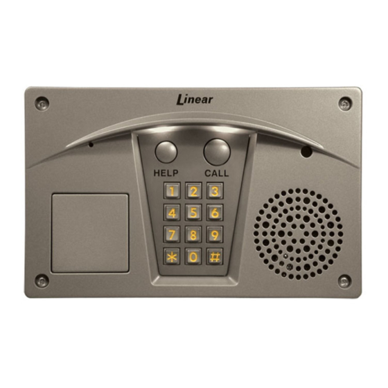
- Page 1 RE-2 Residential Telephone Entry System With Built-in Wireless Receiver Installation, Programming, and Operation Instructions (760) 438-7000 USA & Canada (800) 421-1587 & (800) 392-0123 Toll Free FAX (800) 468-1340 www.linearcorp.com...
-
Page 2: Table Of Contents
• REMOTE KEYPAD SUPPORT RE-2 OPERATION ......21 • BRIGHT WHITE LED DOWNLIGHT •... -
Page 3: Product Description
If the resident decides to grant access Hardwired Activation to the visitor, they can activate either output relay in the RE-2 by The OPEN REQUEST input can be wired to an exit loop detector pressing a key on the telephone’s keypad. If the resident decides or exit photo beam to allow automatic exit activation. -
Page 4: Installation Information
AC line wiring. Power Supply Use the supplied 16-volt 20-VA transformer to power the RE-2. DO NOT POWER ANY OTHER EQUIPMENT FROM THE SAME TRANSFORMER, use a separate power supply. Keep the system power wires as short as practical to reduce the chance of noise and ★... -
Page 5: Component Locations
COMPONENT LOCATIONS HELP BUTTON MAIN TERMINAL BLOCK Pressing this button causes the system to play the help message to For power, backup battery, sense inputs, open request inputs, and instruct the visitor on system use. remote keypad connections. CALL BUTTON 12 STATUS INDICATORS Pressing this button causes the system to call the residence Six indicators light to display system power, radio, and modem... -
Page 6: Wiring Diagram
RE-2 DOOR STRIKE ARE BOTH SHOWN, TELEPHONE ENTRY TYPICALLY ONLY ONE IS USED SYSTEM NOTE: DO NOT POWER ELECTRIC THE LOCKING DEVICE FROM DOOR STRIKE THE RE-2 TRANSFORMER TRANSFORMER ACCESS DEVICE TRANSFORMER POWER BATTERY NEG SUPPLY BATTERY POS SENSE #1... -
Page 7: Entry System Mounting
1. Identify the location of any studs in the wall. Wall Mounting 2. Cut a 10-1/4” wide by 6-1/4” high rectangular hole between studs at The RE-2 Entry System can be mounted directly to a wall or fl at the mounting location. surface. -
Page 8: Telephone Wiring
Dedicated Line • All telephone wiring must be made on the “house” side of the telephone Pressing the Call button on the RE-2 will cause the RE-2 to sieze company’s demarcation device (the terminal block where the telephone the phone line and dial out to an outside number. See PPN #54 for line connects to the residence). -
Page 9: Multiple Unit Installations
Shared Line Mode, putting one RE-2 “on hold” to communicate separate AC transformers to power each RE-2. with the second RE-2, then returning to the fi rst RE-2 is not When multiple units are connected together, only two units can be recommended. -
Page 10: Control Wiring
3. If an external timer for preventing access at certain times is required, • For a door strike, connect the wires to the RE-2 Relay #1 COM & N.O. route two wires from the RE-2 to the timer contacts. Connect the timer terminals. -
Page 11: Power, Battery, & Ground Wiring
GROUND RING KEYPAD PWR TELCO Backup Battery GROUND RE-2 Use of battery backup is optional. It will allow the RE-2 to operate for STAKE TERMINALS GROUND short periods of time without AC power. Two 12-volt backup batteries HOUSE TELCO STAKE in series are recommended to obtain the proper working voltage Figure 16. -
Page 12: Optional Remote Keypad
(see Figure 20). equivalent. 2. Hold the lock cover and plastic spacer in place on the RE-2 case. • For wire runs up to 600 feet use 20 AWG Weico Type 9405 or Secure the assembly with four screws, lock washers, and nuts. Slide equivalent. -
Page 13: Optional Color Cctv Camera
Secure the camera with the two retaining brackets and screws MOUNTING AREA (see Figure 25). 5. Replace the RE-2 circuit board. Secure the board with the six screws. REMOVE THE 6. Connect the camera’s 4-conductor cable to the RE-2’s CAMERA BLACK DOT connector (see Figure 26). -
Page 14: Programming Access
✦ NOTE: The “###” prefi x to access programming is the default value for de-select “IPX/SPX Compatible”. Only “TCP/IP” should be selected. the RE-2. It can be changed in the RE-2 using PPN #72. Be sure the 14. Select “TCP/IP Settings...”. - Page 15 FOR A REMOTE CONNECTION, ENTER THE PHONE NUMBER INFORMATION" ENTER "Linear" AS USER NAME AND SELECT "ADD SHORTCUT" AND CLICK "FINISH" OF THE RE-2'S PHONE LINE. FOR A LOCAL CONNECTION "123456" AS PASSWORD ENTER "###" (THE DEFAULT LOCAL ACCESS PASSWORD) NOTE: "###"...
- Page 16 Remote Telephone Connection changes. Refer to the next section for details of the 1. Dial the telephone number of the line that the RE-2 is connected to. keystrokes for each programming PPN. The voice 2. Let the telephone ring twice and hang up.
-
Page 17: Programming Reference
PROGRAMMING REFERENCE FACTORY DEFAULTS PPN 1 ENTRY CODE LENGTH ......... 4 DIGITS PROGRAMMING CONTROL PPN 8 TRANSMITTER LEFT (OR TOP LEFT) BUTTON ACTIVATES . -
Page 18: Basic System Programming
✦ NOTE: Leading zeros (zeros before the code number, i.e. 0001) do not zones, holiday schedules, and time stamping of the event log. The GTZ need to be entered when programming a new entry code. The RE-2 will setting controls when the downlight is on. The RE-2 has an on-board lithium internally add any zeros to fi... -
Page 19: Transmitter Programming
Action: 0 = Suspend transmitter; 1 = Re-activate transmitter RE-2 will generate beeps on the resident’s telephone line to signal that a Erasing All Transmitters visitor is calling. -
Page 20: Advanced System Programming
RE-2. The resident programming prefi x is entered 5 = On driveway sensor (activates when SENSE #2 input closes) on a local telephone or the main keypad prior to programming the RE-2. Press: Programming Command Programming: 0 = “###”;... - Page 21 Relay #2 Tone On/Off Default: Off in the remote keypad needs to match the “address” setting in the RE-2. For The default setting does not cause the annunciator to sound when Relay #2 most installations, simply set the remote keypad’s ADDRESS switch to “3”...
-
Page 22: System Adjustments
SYSTEM ADJUSTMENTS The RE-2 Entry System audio levels can be adjusted to suit the installation requirements. If required, make these adjustments after programming, but before closing and securing the RE-2 case. Speakerphone Volume The SPEAKERPHONE VOLUME adjustment controls the audio level that the RE-2 speaker produces during communications between the visitor and the resident. -
Page 23: Re-2 Operation
RE-2. • The visitor presses the CALL button. 3. The RE-2 will answer. Wait for the modem tones to fi nish then enter your 6 digit password followed by #. • The RE-2 disconnects the local telephones from the incoming telephone 4. -
Page 24: Resident Programming Quick Reference
RESIDENT PROGRAMMING QUICK REFERENCE Maximum Number of Visitor Rings Some of the programming PPN’s may be commonly used by the Press: Rings resident. Following are quick references to the keystrokes required. Rings = 1-15 Rings maximum ✦ NOTE: The “###” is the default command prefi x. The following example assumes that the default has not been changed. -
Page 25: Specifications
4. Disconnect the house telephone line and connect a test telephone to 10" the RE-2 house ring and tip terminals. See if the test telephone rings. System will not answer an incoming call 1. Modem ring detect (PPN #33) disabled. -
Page 26: Programming Worksheet
PROGRAMMING WORKSHEET F I R F I R F I R F I R S T A S T A S T A S T A 1 1 1 1 1 2 2 2 2 2 3 3 3 3 3 4 4 4 4 4 5 5 5 5 5 6 6 6 6 6... - Page 27 FACILITY 1ST TIME 2ND TIME ENTRY CODE RELAY # TIME ZONE ENTRY CODE RELAY # TIME ZONE TRANSMITTER USER ID CODE TX GROUP CODE ZONE ZONE __ 1 __ 2 __ 1 __ 2 __ 1 __ 2 __ 1 __ 2 __ 1 __ 2 __ 1 __ 2 __ 1 __ 2...
-
Page 28: Linear Limited Warranty
LINEAR LIMITED WARRANTY FCC NOTICE Changes or modifi cations not expressly described in this manual This Linear product is warranted against defects in material and or approved by the manufacturer could void the user’s authority to workmanship for twenty-four (24) months. The Warranty Expiration operate the equipment.
Need help?
Do you have a question about the RE-2 and is the answer not in the manual?
Questions and answers