
Related Manuals for Imagine Videotek VTM-2400


Summary of Contents for Imagine Videotek VTM-2400
- Page 1 Installation and Operation Manual ™ Videotek VTM-2400 Multi-Format HD and SD-SDI Monitor Edition C Item # 061782 Delivering the Moment...
-
Page 2: Contact Information
English without the written consent of Imagine Communications. All others uses are illegal. This publication is designed to assist in the use of the product as it exists on the date of publication of this manual, and may not reflect the product at the current time or an unknown time in the future. -
Page 3: Ensuring Safety
Operator’s Safety Summary WARNING: These instructions are for use by qualified personnel only. To reduce the risk of electric shock, do not perform this installation or any servicing unless you are qualified to do so. Refer all servicing to qualified service personnel. Ensuring Safety The unit should not be exposed to dripping or splashing, and no objects filled with liquids, ... -
Page 4: Important Safety Instructions
Operator’s Safety Summary Use caution when cleaning the equipment; isopropyl alcohol or similar solvents can damage or remove the labels. Observe any additional safety instructions specified in this manual. Important Safety Instructions Read these instructions. Keep these instructions. ... -
Page 5: Explanation Of Symbols
These symbols may appear on Imagine Communications equipment: Certification Labels and Symbol Locations On Imagine Communications equipment, certification labels and symbols are located on the back panel, rear chassis sides, or bottom rear of the chassis. On smaller space-restricted units, most labels and symbols can be found on the bottom rear of the chassis. -
Page 6: Directives And Compliances
Polybrominated Diphenyl Ethers (PBDE) In accordance with this EU Directive, all Imagine Communications products sold in the European Union will be fully RoHS-compliant and “lead-free.” (See the Imagine Communications Premier website for more information on dates and deadlines for compliance.) Spare parts supplied for the repair and upgrade of equipment sold before July 1,... - Page 7 (Some EU member states may have different deadlines.) In accordance with this EU Directive, Imagine Communications and other companies selling electric or electronic devices in the EU will affix labels indicating that such products must be properly recycled.
-
Page 8: Table Of Contents
Contents Operator’s Safety Summary ..................iii Ensuring Safety ........................... iii Important Safety Instructions ....................... iv Explanation of Symbols ........................ v Certification Labels and Symbol Locations .................. v Directives and Compliances ..................vi Restriction on Hazardous Substances (RoHS) Directive 2002/95/EC ........vi Waste from Electrical and Electronic Equipment (WEEE) Directive 2002/96/EC ....... - Page 9 Contents Powering Down from the Front Panel ..................16 Navigating the Pane Setup Menu ....................16 Reference .......................... 17 Pane Overview .......................... 17 Main Title Bar ........................18 Icons ..........................19 Status Bar ......................... 19 The Waveform Display ......................19 Waveform Front Panel Selections ..................
- Page 10 Contents Standard ........................34 Vector Position.......................34 Center Vector.........................34 Vector Setup ........................34 Picture Display ..........................34 Alarm Status Display ........................35 Audio Display ..........................37 Audio Scales ........................37 Vertical Audio Displays ....................38 Expanding the Audio Display .....................41 Presets ............................41 Storing Presets ........................41 Recalling Presets .......................42 Preset 4 (Factory Preset) ....................42 Section 4 ♦...
- Page 11 Contents Persistence ........................57 Attack ..........................57 Audio Setup Menu ......................57 Configure Inputs ......................57 Meter Setup ........................58 AES Validity Bit ......................60 Output Preferences....................... 60 Display Setup ........................60 Display Colors ....................... 61 Graticule Intensity ......................61 Monitor ..........................
- Page 12 Contents EDH ............................71 CRC HD ..........................72 Loss of Carrier ........................72 Digital Gamut ........................72 RGB Upper/Lower ......................72 Section 6 ♦ Troubleshooting .................. 73 Cold Starting the VTM-2400 .......................73 Cold Start ...........................73 Warm Start .........................74 Cold Start after VFlash .......................74 Updating with VFlash ........................74 Problems, Causes, and Solutions ....................74 Appendix A ♦...
- Page 13 Contents Appendix B ♦ Pinouts ..................... 83 Appendix C ♦ RCU-2400 Remote Control Unit ............88 Installing the RCU-2400......................88 Operating the RCU-2400 ......................90 Troubleshooting ......................... 90 Specifications ..........................91 Power Requirements (External Power Supply) ................. 91 Mechanical Specifications ......................91 Environmental Specifications ....................
- Page 14 Contents No Warranty.........................106 GNU Lesser Public License ......................107 GNU Lesser General Public License ................107 Version 2.1, February 1999 ..................107 Preamble ........................107 GNU Lesser General Public License ................109 Terms and Conditions for Copying, Distribution and Modification ......109 No Warranty.........................114 Appendix E ♦ Glossary ..................115 Index ........................
- Page 15 Contents Figure 3-11. Establishing the Sweep Scale ................24 Figure 3-12. Establishing the Gain .................... 25 Figure 3-13. Establishing Line Select ..................26 Figure 3-14. Vector Display Diagram ..................29 Figure 3-15. Vector SD with I/Q ....................31 Figure 3-16. Vector HD 75% + 100% Graticule ................. 31 Figure 3-17.
- Page 16 Contents Table 3-1. Front Panel Description .....................12 Table 3-2. Description of Quad Screen Display .................14 Table 3-3. Description of Icons ....................19 Table 3-4. Video Formats and Units of Measure ................19 Table 3-5. Video Formats and Critical Amplitude Limits ............20 Table 3-6. Description of Waveform Display Diagram ...............21 Table 3-7.
- Page 17 Contents Table 6-1. VTM-2400: Problems, Causes, and Solutions ............74 Table B-1. Pinouts for Analog Audio IN/OUT Connector and Audio Breakout Board ....83 Table B-2. XGA OUT Connector Pinouts .................. 85 Table B-3. Pinouts for GPI/TALLY Connector and GPI/TALLY Breakout Board ....... 86 Table B-4.
-
Page 19: Section 1 ♦ Introduction
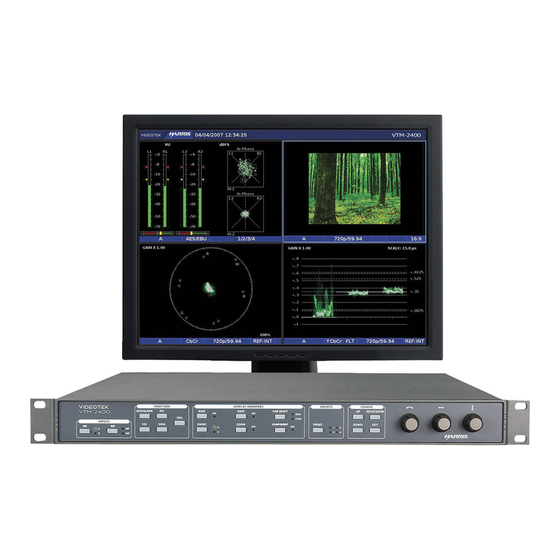
Section 1 ♦ Introduction The VTM-2400 is a multiformat on-screen monitor with waveform monitor, vectorscope, picture, and alarm status. It is a 19-inch rack mounted unit that accepts HD-SDI and SD-SDI video signals, and external analog reference video signals. The display presents the image carried by the selected video input as a real-time, full-motion picture. -
Page 20: Video Standards Supported
Introduction Video Standards Supported The VTM-2400 supports the following video standards: For HD: 1080i/60 1080i/59.94 1080i/50 1080p/30 1080p/29.97 1080p/25 1080p/24 1080p/23.98 1080p/30sF 1080p/29.97sF 1080p/25sF 1080p/24sF 1080p/23.98sF 720p/60 ... -
Page 21: Figure 1-1. Vtm-2400 Front And Back Panels
Introduction The VTM-2400 front and back panels are illustrated in Figure 1-1. Figure 1-1. VTM-2400 Front and Back Panels Front Panel Back Panel VTM-2400 Installation and Operation Handbook... -
Page 22: Service And Support
For service support, telephone the Customer Service Department at 888-534-8246. If the problem cannot be resolved over the telephone and the instrument must be shipped to Imagine Communications for service or repair: Obtain a Return Authorization (RA) number from the Imagine Communications Customer Service Department. -
Page 23: Section 2 ♦ Installation
Inspecting the Shipment Before installing the VTM-2400, inspect the box and the contents. Report any damage to the shipper and telephone the Imagine Communications Customer Service Department for service and support (see “Service and Support” on page 4). NOTE: Refer to the enclosed packing sheet for the latest list of items that are supplied with the unit. -
Page 24: Rack Mounting The Vtm-2400
Installation Rack Mounting the VTM-2400 When selecting the permanent mounting location for the VTM-2400, ensure that the flow of air to the ventilation holes on the sides of the chassis is not obstructed. Rack mounting the VTM-2400 is illustrated in Figure 2-1. The parts required to rack mount the VTM-2400 are listed in Table 2-1. -
Page 25: Connecting The Vtm-2400
Installation Connecting the VTM-2400 The back panel connectors are illustrated in Figure 2-2, and the function of each connector is described in Table 2-2. Figure 2-2. VTM-2400 Back Panel Connectors Table 2-2. Description of Back Panel Connectors Label Description Female BNC connectors that connect to an external reference signal (NTSC/PAL video, blackburst, or tri-level) from which the horizontal and vertical sync for the VTM-2400 will be derived if EXT has been selected as the REF source. - Page 26 Installation These addresses are: A static IP address (unless Dynamic Host Configuration Protocol (DHCP) will be used) A Subnet Mask An optional Gateway IP Be sure to record all addresses. The Gateway address is only needed if the VTM-2400 is routed to an outside network.
-
Page 27: Figure 2-3. Vtm-2400 Dedicated Pc Connection
Installation Record the addresses: VTM-2400 Interface Static IP Address VTM-2400 Interface Subnet Mask Gateway IP Address Identify a host PC to configure and test the VTM-2400. 3a. For a dedicated PC connection, connect the host PC with a network card to the “VFLASH” connector on the back panel of the VTM-2400, using a CAT5 crossover cable (not included). -
Page 28: Figure 2-4. Vtm-2400 Network Pc Connection
Installation Figure 2-4. VTM-2400 Network PC Connection 4. Ethernet Configuration a) Press the SETUP/ENTER button on the VTM front panel. b) Press the UP or DOWN button to highlight the COMMUNICATIONS menu, and then press the SETUP/ENTER button to enter the submenu. c) Press the UP or DOWN button until the IP CONFIGURATION submenu is highlighted. -
Page 29: Configuring The Vtm/Tvm Series With The Rcu-2400 Remote Control
Installation Configuring the VTM/TVM Series with the RCU-2400 Remote Control For the following configurations, the interconnecting cables can be extended using electronic distribution. There are two ways to configure the VTM-2400 with the RCU-2400 remote control: One RCU-2400 connected to one VTM-2400 unit using the REMOTE port. ... -
Page 30: Section 3 ♦ General Operation
Section 3 ♦ General Operation Terms Pane: One quadrant in a four-quadrant screen. Display: The output that appears on the XGA monitor. Quad: Screen that contains four panes. Full: Full-screen display of the selected pane (non quad). Introduction to Operating the VTM-2400 The VTM-2400, shown in Figure 3-1 and described in Table 3-1, can display four panes on the screen in quad mode, which provides a fixed display of waveform (lower-right), vector (lower- left), audio (option) and alarm status (upper-left), and picture (upper-right). - Page 31 General Operation Table 3-1. Front Panel Description Label Description FULL Press to show a full-screen display of the selected pane. Press to highlight the Vector pane. Press and hold to access the Vector Pane menu. Press to highlight the Waveform pane. ...
-
Page 32: Figure 3-2. Sample Multi-Display
General Operation Table 3-1. Front Panel Description Label Description CURVED ARROW Rotate the knob to change the line number when line select is enabled. KNOB Rotate the knob to move in the menu (Global or Pane menu). LEFT/RIGHT ARROW Rotate the knob to move the waveform left and right. -
Page 33: Types Of Controls
General Operation Table 3-2. Description of Quad Screen Display Description Audio meters Audio phase bar. Indicates the input selection Indicates the Audio format and input channels Indicates the format selection. Vector Gain indication. Vector display of the selected input. Indicates the detected or selected video standard. Indicates the reference source. -
Page 34: Selecting A Pane
General Operation Selecting a Pane When multiple panes are displayed, only one pane can be selected at a time. The active pane is highlighted with a bright colored border. Press the desired function button to select the active pane to be configured, as shown in Figure 3-3. Figure 3-3. -
Page 35: Reference
General Operation Press to select a menu item or open a menu or submenu. − Press to move up in the menu or submenu. − Press to move down in the menu or submenu. − Rotate the knob to move the menu cursor up and down or to change a −... -
Page 36: Main Title Bar
General Operation Figure 3-4. Sample Quad Diagram Figure 3-5. Full-Screen Display Diagram Main Title Bar The main title bar is displayed at the top of the screen, and contains the company name, date and time, icon indicators, most current alarm (alarm background color is yellow when active), and the model name. -
Page 37: Icons
General Operation Icons Icons appear in the main title bar and are shown in a specified order (left to right). Table 3-3 shows the icons and the condition for the appearance: Table 3-3. Description of Icons Icon Condition Alarm condition active. RCU connected and active. -
Page 38: Figure 3-6. Waveform Display Diagram
General Operation Table 3-5. Video Formats and Critical Amplitude Limits Video Format Critical Amplitude Limits High Definition and Standard Definition 0.6125 V = upper 75% chroma limit 0.525 V = 75% luminance limit 0.350 V = 50% point; black for color difference channels ... -
Page 39: Table 3-6. Description Of Waveform Display Diagram
General Operation Table 3-6. Description of Waveform Display Diagram Field Identifier Field Information Nomenclature Input Displays the input. Format Displayed as YC , RGB, or YRGB. YC , RGB, or YRGB can be selected in the HD FORMAT submenu of the WFM Pane menu. -
Page 40: Figure 3-7. Rgb And Yc B C R Graticule
General Operation Figure 3-7. RGB and YC Graticule Figure 3-8. RGB and YC Zoom 0 mV Graticule Figure 3-9. RGB and YC Zoom 700 mV Graticule VTM-2400 Installation and Operation Handbook... -
Page 41: Waveform Front Panel Selections
General Operation Waveform Front Panel Selections The following controls directly affect the waveform display. Moving the Waveform using the Setup Knobs Move the Waveform display relative to the graticule by using the LEFT/RIGHT NAVIGATION knob (for horizontal movement) and the UP/DOWN NAVIGATION knob (for vertical movement), as shown in Figure 3-10. -
Page 42: Mag Button
General Operation Figure 3-11. Establishing the Sweep Scale For horizontal sweeps, press the SWEEP button to select 1H. For vertical sweeps, press the SWEEP button to select 1V. MAG Button Press the MAG button to change the horizontal magnification or to turn the magnification OFF. -
Page 43: Zoom Button
General Operation Figure 3-12. Establishing the Gain Zoom Button Press the ZOOM button to cycle through one of three display selections: ZOOM positioned on the 0 mV or 0% graticule line ZOOM positioned on the 700 mV or 100% graticule line ... -
Page 44: Waveform Pane Menu Selections
General Operation Figure 3-13. Establishing Line Select 1. Press the LINE SELECT button again to alternate between the ODD, EVEN, and all fields. 1. Rotate the CURVED ARROW knob to select the line to be displayed. Waveform Pane Menu Selections Pressing and holding the WFM button enables the Waveform pane menu. -
Page 45: Table 3-8. Waveform (Sd-Sdi) Menu Structure
General Operation Table 3-7. Waveform (HD-SDI) Menu Structure Selection Selection Option BLANKING BLANK ALL SHOW SAV/EAV SHOW ALL COMPONENT SEQUENCE If YC is selected (Y, C If RGB is selected (R, G, B) If YRGB is selected (Y, R G B) CENTER WAVEFORM Press ENT WAVEFORM SETUP... -
Page 46: Filter Selection
General Operation Table 3-8. Waveform (SD-SDI) Menu Structure Selection Selection Option If RGB is selected (R, G, B) If YRGB is selected (Y, R, G B) CENTER WAVEFORM Press SETUP/ENTER WAVEFORM SETUP Press SETUP/ENTER Filter Selection The filters available are: Flat: No filtering. -
Page 47: Component Sequence
General Operation “Show All” displays the ancillary data, SAV/EAV, and active video. Component Sequence Select to enable the component Y, C , and C when YC is selected in the HD or SD Format menu; Y, R, G, and B, when YRGB is selected in the HD or SD FORMAT menu. Center Waveform Press the SETUP/ENTER button to activate the Center Waveform selection. -
Page 48: Table 3-9. Description Of Vector Display Diagram
General Operation Table 3-9. Description of Vector Display Diagram Field Identifier Field Information Nomenclature Input Displays the input. Format Displayed as C Standard Displays the Line Rate/Frame Rate [1080i/59.94]. This is selected in the VIDEO FORMAT\VIDEO A CONFIGURE or B CONFIGURE menu. -
Page 49: Gain Button
General Operation Figure 3-15. Vector SD with I/Q Figure 3-16. Vector HD 75% + 100% Graticule Gain Button The standard gain in the vector is x1.00. The VTM-2400 can be used to set the gain amplification in the video signal using the Gain button. The gain setting appears in the upper-left portion of the vector pane, as shown in Figure 3-17. -
Page 50: Zoom Button
General Operation Figure 3-17. Establishing the Vector Gain Press the GAIN button to step through the available gain selections x1.00, x2.50, and x5.00. Zoom Button Press ZOOM to cycle through one of six displays: Expand the center Expand the upper-left quadrant ... -
Page 51: Placing The Vector Display In Line Select Mode
General Operation Placing the Vector Display in Line Select Mode NOTE: Vector Line Select only functions when in 1H sweep or full screen. Pressing the LINE SELECT button enables the vector pane to monitor a single line of a video signal. This enables Line Select to monitor individual areas of the entire image. -
Page 52: Standard
General Operation Table 3-10. Vector Pane Menu Selection Selection Option CENTER VECTOR Press SETUP/ENTER SETUP Press SETUP/ENTER Standard Standard is used to set the marks on the vector display. The marks on the vector help to visualize the minimum/maximum value of a video signal. The position of the excursion marks are 75% or 100% for HD and SD. -
Page 53: Alarm Status Display
General Operation Figure 3-19. Picture Display Diagram Table 3-11. Description of Picture Display Diagram Field Identifier Field Information Nomenclature Input Displays the input. Standard Displays the Line Rate/Frame Rate [1080i/59.94]. Select the Standard in the VIDEO FORMAT\VIDEO A or B CONFIGURE menu. -
Page 54: Figure 3-20. Alarm Status Display Diagram
General Operation The Alarm Status Display lists all the alarms, the state of each alarm setting, the current alarm limit selection (if applicable), the current alarm duration (if applicable), and the Total alarm column. An alarm status display diagram is shown in Figure 3-20 and described in Table 3-12. The diagram illustrates the general location for the various alarm status display fields. -
Page 55: Audio Display
General Operation The total alarm count can be cleared through the Alarm Status pane menu. Press and hold the AUD/ALARM button to display the Alarm Status pane menu. The Alarm Status pane menu is described in Table 3-13. Table 3-13. Alarm Status Pane Menu Selection Selection Option CLEAR ALARM COUNT... -
Page 56: Vertical Audio Displays
General Operation Nordic DIN 45406 dBFS (Digital only) Zero Ref dBFS (ref –20 dBFS) (Digital only) Vertical Audio Displays The Vertical Meter displays the level and reference in a vertical format. There are four analog audio input channels (two stereo pairs), four AES/EBU digital input channels (four stereo pairs), and 16 embedded audio channels (eight stereo pairs) available for selection in the menu. -
Page 57: Figure 3-21. Two Bar Graph Display With Lissajous Diagram
General Operation Figure 3-21. Two Bar Graph Display with Lissajous Diagram Table 3-14. Description of Two Bar Graph Display with Lissajous Diagram Field Identifier Field Information Nomenclature Input Displays the video input associated with the audio. Audio Type Displayed as Analog, AES/EBU, or Embedded Audio Input Monitored Audio channels that are associated with the meters. -
Page 58: Figure 3-22. Four Bar Graph With Lissajous Display Diagram
General Operation Table 3-14. Description of Two Bar Graph Display with Lissajous Diagram Field Identifier Field Information Nomenclature Blank when disabled Peak Program and Shows the peak and reference levels for the signal. This can Reference Level Markers be adjusted in the AUDIO SETUP\METER SETUP\REF LEVEL DIGITAL (or ANALOG) menu and Peak Program Level and Analog menus. -
Page 59: Expanding The Audio Display
General Operation Table 3-15. Description of Four Bar Graph with Lissajous Display Diagram Field Identifier Field Information Nomenclature Scale Selection Displays the selected meter scale: Type I, Type IIa, Type IIb, Type I + 8, Nordic, DIN 45406, dBFS, Zero REF dBFS (scales dependent upon audio type). -
Page 60: Recalling Presets
General Operation ii. Press and hold the PRESET button until the preset LEDs blink. The blinking LED next to Preset 1 indicates that it is ready to store the new settings. iii. Press the PRESET button to advance to the desired preset number. The blinking LED indicates that it is ready to store the new settings in the selected preset. -
Page 61: Section 4 ♦ Global Setup Menu Functions
Section 4 ♦ Global Setup Menu Functions Navigating the Setup Menu Press the SETUP button to access the global setup menu. Use the SETUP POSITION knobs or the SETUP/ENTER, UP, DOWN, and EXIT buttons to navigate the Global Setup menu. The SETUP POSITION knobs and Navigation buttons are described below: - Press to enter the Setup menu. -
Page 62: Table 4-1. Setup Menu Tables
Global Setup Menu Functions Table 4-1. Setup Menu Tables Setup Menu Item Table Page Description Page Video Format Waveform Setup Vector Setup Audio Setup Audio Alarms Video Alarms, Digital Display Setup Communications System About *NOTE: The alarm descriptions are in Section 5, “Alarm Descriptions.” Table 4-2. - Page 63 Global Setup Menu Functions Table 4-2. Video Format Menu Selection Selection Option Selection Option 1080p/29.97sF 1080p/25sF 1080p/24sF 1080p/23.98sF 720p/60 720p/59.94 720p/50 720p/30 720p/29.97 720p/24 720p/23.98 625/50 525/59.94 VIDEO B CONFIGURE AUTODETECT (Default) 1080i/60 1080i/59.94 1080i/50 1080p/30 1080p/29.97 1080p/25 1080p/24 1080p/23.98 1080p/30sF 1080p/29.97sF VTM-2400 Installation and Operation Handbook...
-
Page 64: Table 4-3. Waveform Setup Menu
Global Setup Menu Functions Table 4-2. Video Format Menu Selection Selection Option Selection Option 1080p/25sF 1080p/24sF 1080p/23.98sF 720p/60 720p/59.94 720p/50 720p/30 720p/29.97 720p/24 720p/23.98 625/50 525/59.94 Table 4-3. Waveform Setup Menu Selection Selection Option DIGITAL WAVEFORM GRATICULE PERCENT VOLTS (Default) WAVEFORM INTENSITY 25% TO 200% (100% NORMAL) WAVEFORM CONTRAST... -
Page 65: Table 4-4. Vector Setup Menu
Global Setup Menu Functions Table 4-4. Vector Setup Menu Selection Selection Option SD I/Q LINES OFF (Default) VECTOR INTENSITY 25% TO 200% (100% is NORMAL) VECTOR CONTRAST 25% TO 200% (100% is NORMAL) PERSISTENCE NORMAL, 1 TO 6, & INFINITE (NORMAL is Default) ATTACK LOW, 2 TO 6, MAX (LOW is Default) - Page 66 Global Setup Menu Functions Table 4-5. Audio Setup Menu Selection Selection Option Selection Option Selection Option Selection Option REF LEVEL -22 TO –8 (1 dB DIGITAL (dBFS) STEPS) (-20 is the default) PEAK PROGRAM TYPE I 1 TO 11 dB (8 dB LEVEL ANL is Default) (ANALOG)
- Page 67 Global Setup Menu Functions Table 4-5. Audio Setup Menu Selection Selection Option Selection Option Selection Option Selection Option TYPE IIa TYPE IIb TYPE I + 8 NORDIC DIN 45406 DIGITAL SCALE TYPE I TYPE IIa TYPE IIb TYPE I + 8 NORDIC DIN 45406 dBFS (Default)
- Page 68 Global Setup Menu Functions Table 4-5. Audio Setup Menu Selection Selection Option Selection Option Selection Option Selection Option SETUP INTENSITY is DEFAULT) LISSAJOUS 25% TO 200% CONTRAST (NORMAL/100% is DEFAULT) PERSISTENCE NORMAL, 1 TO 6, INFINITE (NORMAL is the Default) ATTACK LOW, 2 TO 6, MAX (LOW is the...
-
Page 69: Table 4-6. Audio Alarms Menu
Global Setup Menu Functions Table 4-6. Audio Alarms Menu Selection Selection Option Selection Option Selection Option PEAK AUDIO ANALOG ENABLE CH 1 ENABLE CH 2 ENABLE CH 3 ENABLE CH 4 ANALOG LEVEL -6 TO 24 dBu (24 dBu is Default) DURATION 0 TO 60 SECONDS (2... -
Page 70: Table 4-7. Video Alarms, Digital Menu
Global Setup Menu Functions Table 4-6. Audio Alarms Menu Selection Selection Option Selection Option Selection Option ENABLE CH 3 ENABLE CH 4 DIGITAL LEVEL -60 TO 0 dBFS (-60 dBFS is Default) DURATION 0 TO 60 SECONDS (2 Seconds is Default) Table 4-7. -
Page 71: Table 4-8. Display Setup Menu
Global Setup Menu Functions Table 4-7. Video Alarms, Digital Menu Selection Selection Option Selection Option Selection Option EDH (SD only) ENABLE OFF (Default) DURATION 0 TO 60 Seconds (2 Seconds is Default) ENABLE OFF (Default) DURATION 0 TO 60 Seconds (2 Seconds is Default) Table 4-8. -
Page 72: Table 4-9. Display Colors Menu
Global Setup Menu Functions Table 4-9. Display Colors Menu Display Colors GRAT BKGD Black Blue Green Cyan Purple LT Gray DK Gray LT Blue LT Green LT Cyan LT Red LT Purple Yellow White Table 4-10. Communications Setup Menu Selection Selection Option Selection Option Selection Option... -
Page 73: Table 4-11. System Setup Menu
Global Setup Menu Functions Table 4-10. Communications Setup Menu Selection Selection Option Selection Option Selection Option POLARITY (Default) NORMALLY CLOSED UNIT ID 1 TO 99 (1 is Default) Table 4-11. System Setup Menu Selection Selection Option Selection Option Selection Option PANEL LOCKOUT ENTER PASSWORD SCREEN... -
Page 74: Video Format Menu
Global Setup Menu Functions Table 4-12. About Menu Selection Selection Option Selection Option Selection Option ABOUT ABOUT SCREEN Video Format Menu The Video Format menu items are described below. Video A and B Configure The Video “A and B” Configure menu is used to automatically or manually select the video format reference standard for the selected input. -
Page 75: Vector Setup Menu
Global Setup Menu Functions Vector Setup Menu The Vector Setup menu is used to select the SDI I/Q Lines, Vector Intensity, Vector Contrast, Persistence, and Attack. SD I/Q Lines The SD I/Q Lines submenu is used to turn OFF and ON the I and Q marker lines on the Vector Display. -
Page 76: Meter Setup
Global Setup Menu Functions Audio Display The VTM-2400 instrument is capable of displaying analog or digital audio. To take advantage of this flexibility, use the AUDIO SETUP menu to select specifications unique to the studio environment. Configure the audio display type and parameters using the AUDIO SETUP CONFIGURE INPUT A to B submenu. -
Page 77: Table 4-13. Ballistic Specifications With Attack And Decay
Global Setup Menu Functions Meter Response Ballistics specifications are shown in Table 4-13. These specifications describe meter scale markings and both attack and decay times for meter movement. Table 4-13. Ballistic Specifications with Attack and Decay Ballistic Name Standard Attack Decay IEC 268-17 300 ms... -
Page 78: Aes Validity Bit
Global Setup Menu Functions Lissajous Display Select to determine the type of Lissajous display that appears in the Audio pane. There are two types of Lissajous displays (Soundstage and X-Y). The soundstage selection displays a lissajous, which is rotated so that the in-phase signals appear on the vertical axis and out of phase signals appear on the horizontal axis. -
Page 79: Display Colors
Global Setup Menu Functions Display Colors The display colors are used to select the colors for the background, signals, and graticules of the VTM-2400. The colors are listed in Table 4-9 on page 54. The Display Color Selection Screen, shown in Figure 4-1, is used to set the colors. Any color selection that is not available is blocked out and not selectable. -
Page 80: Time Code
Global Setup Menu Functions OFF disables the screen saver. When the screen saver is activated, press any button to turn the display back on. Output Level The Output Level submenu is used to determine the monitor output level. The default monitor output level is 1V p-p. -
Page 81: Gpi Output Function
Global Setup Menu Functions TCP/IP stack is fully compliant with RFC2500, “Internet Official Protocol Standards” Fully compliant with the IEEE 802.3 Ethernet standard The interface can accept a static IP address, or it can obtain an IP address dynamically from a DHCP server. -
Page 82: Unit Id
Global Setup Menu Functions GPI Output Polarity There is one GPI output that is associated with a list of alarms. All GPI alarm activation selections are set to the default OFF until the alarm is enabled. When an alarm is enabled, the GPI functions according to the GPI OUTPUT POLARITY setting (NORMALLY OPEN, NORMALLY CLOSED). - Page 83 Global Setup Menu Functions 2. Press the SETUP/ENTER button to display the SETUP MENU. 3. Use the UP or DOWN buttons (or the UP/DOWN NAVIGATION knob) to move the cursor to the SYSTEM menu. 4. Press the SETUP/ENTER button. 5. Use the UP or DOWN buttons (or the UP/DOWN NAVIGATION knob) to move the cursor to PANEL LOCKOUT.
- Page 84 Global Setup Menu Functions 2. Use the UP or DOWN buttons to select 0-9 (first digit in password). 3. Use the SETUP/ENTER button to move the cursor to the second password number. 4. Use the UP or DOWN buttons to select 0-9 (second digit in password). 5.
-
Page 85: Set Time
Global Setup Menu Functions 13. Use the UP or DOWN buttons (or the UP/DOWN NAVIGATION knob) to select 0-9 (first digit in the new password). 14. Use the SETUP/ENTER button to move the cursor to the second password number. 15. Use the UP or DOWN buttons (or the UP/DOWN NAVIGATION knob) to select 0-9 (second digit in the new password). -
Page 86: About
Global Setup Menu Functions About The About Screen, shown in Figure 4-4, contains the model, serial number, module, device, and version. Press the EXIT or SETUP/ENTER, or turn the LEFT/RIGHT control knob to exit from the screen. Figure 4-4. About Screen VTM-2400 Installation and Operation Handbook... - Page 87 Global Setup Menu Functions This page is intentionally blank. VTM-2400 Installation and Operation Handbook...
-
Page 89: Section 5 ♦ Alarm Descriptions
Section 5 ♦ Alarm Descriptions Setting Alarms Limits are selected in the SETUP Menu by choosing a value using the UP/DOWN or CURVED ARROW knobs, or the UP or DOWN Navigation buttons. Sensitivity and Duration are two general terms used in the alarm menus: Sensitivity ... -
Page 90: Crc Hd
Alarm Descriptions CRC HD The CRC HD alarm occurs when the internally calculated CRC value is different from the received CRC value (High definition only). Table 5-1. CRC Alarm Error Types Error Type Description CRC ERRORED The integer number of seconds in which an EDH or CRC error has existed. SECONDS SAV PLACED SAV is relative to EAV. -
Page 91: Section 6 ♦ Troubleshooting
Section 6 ♦ Troubleshooting CAUTION: These instructions are for use by qualified personnel only. To reduce the risk of electric shock, do not perform this installation or any servicing unless you are qualified to do so. Refer all servicing to qualified service personnel. NOTE: When power is applied to the unit, the display shows the startup screen for about 25 seconds. -
Page 92: Warm Start
Updating with VFlash The VTM-2400 is updated using the VFlash program. Obtain the latest .flu file from th3e Imagine Communications Premier website and follow the instructions in the VFlash User Guide located on the VFlash CD to update the device. - Page 93 Troubleshooting Table 6-1. VTM-2400: Problems, Causes, and Solutions Problem/Symptom Possible Cause Solution or Explanation Waveform not locked when The video signal is too low in Verify that the External Reference External Reference amplitude or the sync edge is too signal is of sufficient amplitude. (EXT REF) is selected noisy.
- Page 94 Troubleshooting This page is intentionally blank. VTM-2400 Installation and Operation Handbook...
-
Page 95: Appendix A ♦ Specifications
Appendix A ♦ Specifications Specifications are subject to change without notice. Video Specifications Item Specification Inputs A and B (Digital) Two (2) serial digital interface inputs accepting high definition and standard definition formats. Standards SMPTE 259MC-1997, ITU-R BT.601, SMPTE 292M-1998, SMPTE 296M-2001, SMPTE 299M-2004, SMPTE 291M-1998, SMPTE 334M-2000, SMPTE 272M-2004, SMPTE 294M-2001, and SMPTE 276M-1995... - Page 96 Specifications Audio Specifications Item Specification Outputs (Analog) Four monophonic or two stereo channels, balanced or unbalanced, follows selected audio input. Output level +24 dBu max +6 to –50 dB adjustable For digital audio, -20 dBFs produces a +4 dBu analog output level Output connector 37-pin D-sub, male, shared with inputs Impedance...
-
Page 97: Control Specifications
Specifications Control Specifications Item Specification Two total for input select A and B. One summary alarm Connector 15-pin HD (high density) D-sub, female Input Impedance 10 kΩ returned to +5 VDC Alarm Output Relay closure Maximum relay current 350 mA @ 30 VDC Remote One RJ-11 female for use with the RCU-2400 Display Specifications... -
Page 98: Magnification Specifications
Specifications Magnification Specifications Item Specification Waveform Sweep MAG x1.00, x5.00, and x10.00. Pressing the MAG button will cycle through selection x1.00, x5.00, and x10.00 horizontal magnification. Waveform Step Gain x1.00, x2.50, and x5.00. Pressing the ZOOM button will cycle through selection x1.00, x2.50, and x5.00 magnification. -
Page 99: Vflash Specifications
Specifications VFlash Specifications Item Specification Standard 10/100 Base-T conforms to IEEE802.3 Connector RJ-45 Remote Control Specifications Item Specification Communications Number of multidrop inputs Physical interconnection RJ-11 standard Power Requirements Item Specification AC power source 90 – 264 VAC, 50 - 60 Hz, nominal Power consumption 90 W maximum Mechanical Specifications... -
Page 100: Standard Accessories
Specifications Standard Accessories Item Specification Standard accessories VTM-2400 Installation and Operation Handbook Breakout connector for LTC/GPI One Rack Mounting Kit One Power Cord Options Item Specification VTM-A -OPT1 Advanced audio analysis option. Display 2 or 4 channels with bar graph and lissajous. -
Page 101: Appendix B ♦ Pinouts
Appendix B ♦ Pinouts Figure B-1. Analog Audio IN/OUT 37-Pin, Male, D-Sub Connector for Audio Option Table B-1. Pinouts for Analog Audio IN/OUT Connector and Audio Breakout Board Pinout Signal Pinout Signal Analog input 1 – Analog input 1 + Analog input 2 –... - Page 102 Pinouts Figure B-1. Analog Audio IN/OUT 37-Pin, Male, D-Sub Connector for Audio Option Table B-1. Pinouts for Analog Audio IN/OUT Connector and Audio Breakout Board Pinout Signal Pinout Signal VTM-2400 Installation and Operation Handbook...
-
Page 103: Figure B-2. Xga Out 15-Pin, Female, D-Sub Connector
Pinouts Figure B-2. XGA OUT 15-Pin, Female, D-Sub Connector Table B-2. XGA OUT Connector Pinouts Pinout Signal Pinout Signal XGA red output N.C. XGA green output XGA blue output N.C. N.C. N.C./SDA XGA horizontal sync output XGA vertical sync output N.C./SCL VTM-2400 Installation and Operation Handbook... -
Page 104: Figure B-3. Gpi/Tally Connector
Pinouts Figure B-3. GPI/TALLY Connector Figure B-4. GPI/TALLY Breakout Board Table B-3. Pinouts for GPI/TALLY Connector and GPI/TALLY Breakout Board Pinout Signal Pinout Signal ERROR SUM LTC GND Select input A LTC+ Select input B LTC- CLK+ (Clock +) CLK GND ERROR SUM RETURN CLK - VTM-2400 Installation and Operation Handbook... -
Page 105: Figure B-5. Remote Rj-11 Control Connector
Pinouts Figure B-5. Remote RJ-11 Control Connector Table B-4. Remote RJ-11 Control Connector Pinouts Pinout Signal VTM-2400 RCU-2400 OPEN Open RX - Received by VTM-2400 Transmit from RCU RX + Received by VTM-2400 Transmit from RCU TX - Transmit from VTM-2400 Received by RCU TX + Transmit from VTM-2400... -
Page 106: Appendix C ♦ Rcu-2400 Remote Control Unit
Appendix C ♦ RCU-2400 Remote Control Unit The RCU-2400 remote control unit enables remote control of as many as 30 VTM-2400s. Installing the RCU-2400 Figure C-1. RCU- 2400 Front and Back Panel Views Table C-1. Description of RCU-2400 Back Panel Connectors Label Description TO MAIN UNIT... -
Page 107: Figure C-2. Connecting The Rcu To Multiple Vtm-2400S
RCU-2400 Remote Control Unit 5. Physically connect the RCU-2400 to a bus with one or more VTM-2400 instruments using a multidrop cabling adaptor and straight through cable using RJ-11 connectors (not a standard telephone wire) that connects to the REMOTE ports on the back of the VTM-2400 instruments and to the TO MAIN UNIT connector on the back of the RCU, as illustrated in Figure C-2. -
Page 108: Operating The Rcu-2400
RCU-2400 Remote Control Unit RCU-2400 LEDs now reflect the settings of the attached VTM-2400 instrument. The RCU-2400 front panel operations affect the VTM-2400 instrument. 9. The VTM-2400 polls the selected RCU-2400 every five seconds. If the VTM-2400 instrument fails to receive the poll after 60 seconds, the RCU-2400 assumes that a communication break has occurred. -
Page 109: Specifications
RCU-2400 Remote Control Unit Specifications Specifications are subject to change without notice. Power Requirements (External Power Supply) Item Specification AC power source 115–230 VAC, 50/60 Hz nominal Power consumption 30 VA maximum DC output Mechanical Specifications Item Specification Dimensions Height: 1.75 in. -
Page 110: Standard Accessories
RCU-2400 Remote Control Unit Standard Accessories Item Specification Standard accessories DC power supply (115–230 VAC, 50–60 Hz capability) with detachable AC power cord 50' RCU-2400 RJ-11 interface cable VTM-2400 Installation and Operation Handbook... -
Page 111: Pinouts
RCU-2400 Remote Control Unit Pinouts Figure C-3. RCU-2400 to Main Unit RJ-11 Connector Table C-3. Pinouts for RCU-2400 to Main Unit Connector Pinout Signal Transmit from RCU Transmit from RCU Received by RCU Received by RCU VTM-2400 Installation and Operation Handbook... - Page 112 RCU-2400 Remote Control Unit This page is intentionally blank. VTM-2400 Installation and Operation Handbook...
-
Page 113: Appendix D ♦ Open Source Software Copyright Information
Copyright information for certain Open Source software products is provided below. Source code for all Open Source software used in the development of this product is available upon request (contact the Imagine Communications Customer Service Department). See “Service and Support” on page 4 for contact information. -
Page 114: Networks Associates Technology, Inc. Copyright Notice (Bsd)
Open Source Software Copyright Information Networks Associates Technology, Inc. Copyright Notice (BSD) Copyright © 2001-2003, Networks Associates Technology, Inc. All rights reserved. Redistribution and use in source and binary forms, with or without modification, are permitted provided that the following conditions are met: Redistributions of source code must retain the above copyright notice, this list of ... -
Page 115: Cambridge Broadband Ltd. Copyright Notice (Bsd)
Open Source Software Copyright Information Cambridge Broadband Ltd. Copyright Notice (BSD) Portions of this code are copyright © 2001-2003, Cambridge Broadband Ltd. All rights reserved. Redistribution and use in source and binary forms, with or without modification, are permitted provided that the following conditions are met: Redistributions of source code must retain the above copyright notice, this list of ... -
Page 116: Sun Microsystems, Inc. Copyright Notice (Bsd)
Open Source Software Copyright Information Sun Microsystems, Inc. Copyright Notice (BSD) Copyright © 2003 Sun Microsystems, Inc., 4150 Network Circle, Santa Clara, California 95054, U.S.A. All rights reserved. Use is subject to license terms below. This distribution may include materials developed by third parties. Sun, Sun Microsystems, the Sun logo and Solaris are trademarks or registered trademarks of Sun Microsystems, Inc. -
Page 117: Sparta, Inc. Copyright Notice (Bsd)
Open Source Software Copyright Information Sparta, Inc. Copyright Notice (BSD) Copyright © 2003-2008, Sparta, Inc. All rights reserved. Redistribution and use in source and binary forms, with or without modification, are permitted provided that the following conditions are met: Redistributions of source code must retain the above copyright notice, this list of ... -
Page 118: Cisco/Buptnic Copyright Notice (Bsd)
Open Source Software Copyright Information Cisco/BUPTNIC Copyright Notice (BSD) Copyright © 2004, Cisco, Inc and Information Network Center of Beijing University of Posts and Telecommunications. All rights reserved. Redistribution and use in source and binary forms, with or without modification, are permitted provided that the following conditions are met: Redistributions of source code must retain the above copyright notice, this list of ... -
Page 119: Fabasoft R&D Software Gmbh & Co. Kg Copyright Notice (Bsd)
Open Source Software Copyright Information Fabasoft R&D Software GmbH & Co. KG Copyright Notice (BSD) Copyright © Fabasoft R&D Software GmbH & Co. KG, 2003 oss@fabasoft.com. Author: Bernhard Penz Redistribution and use in source and binary forms, with or without modification, are permitted provided that the following conditions are met: Redistributions of source code must retain the above copyright notice, this list of ... -
Page 120: The Gnu V2 License
Open Source Software Copyright Information The GNU v2 License GNU General Public License Version 2, June 1991 Copyright © 1989, 1991 Free Software Foundation, Inc., 51 Franklin Street, Fifth Floor, Boston, MA 02110-1301 USA. Everyone is permitted to copy and distribute verbatim copies of this license document, but changing it is not allowed. -
Page 121: Gnu General Public License
Open Source Software Copyright Information GNU General Public License Terms and Conditions for Copying, Distribution and Modification 0. This License applies to any program or other work which contains a notice placed by the copyright holder saying it may be distributed under the terms of this General Public License. The “Program,”... - Page 122 Open Source Software Copyright Information These requirements apply to the modified work as a whole. If identifiable sections of that work are not derived from the Program, and can be reasonably considered independent and separate works in themselves, then this License, and its terms, do not apply to those sections when you distribute them as separate works.
- Page 123 Open Source Software Copyright Information place counts as distribution of the source code, even though third parties are not compelled to copy the source along with the object code. 4. You may not copy, modify, sublicense, or distribute the Program except as expressly provided under this License.
-
Page 124: No Warranty
Open Source Software Copyright Information 8. If the distribution and/or use of the Program is restricted in certain countries either by patents or by copyrighted interfaces, the original copyright holder who places the Program under this License may add an explicit geographical distribution limitation excluding those countries, so that distribution is permitted only in or among countries not thus excluded. -
Page 125: Gnu Lesser Public License
Open Source Software Copyright Information GNU Lesser Public License GNU Lesser General Public License Version 2.1, February 1999 Copyright © 1991, 1999 Free Software Foundation, Inc., 51 Franklin Street, Fifth Floor, Boston, MA 02110-1301 USA. Everyone is permitted to copy and distribute verbatim copies of this license document, but changing it is not allowed. - Page 126 Open Source Software Copyright Information Finally, software patents pose a constant threat to the existence of any free program. We wish to make sure that a company cannot effectively restrict the users of a free program by obtaining a restrictive license from a patent holder. Therefore, we insist that any patent license obtained for a version of the library must be consistent with the full freedom of use specified in this license.
-
Page 127: Gnu Lesser General Public License
Open Source Software Copyright Information GNU Lesser General Public License Terms and Conditions for Copying, Distribution and Modification 0. This License Agreement applies to any software library or other program which contains a notice placed by the copyright holder or other authorized party saying it may be distributed under the terms of this Lesser General Public License (also called “this License”). - Page 128 Open Source Software Copyright Information c) You must cause the whole of the work to be licensed at no charge to all third parties under the terms of this License. d) If a facility in the modified Library refers to a function or a table of data to be supplied by an application program that uses the facility, other than as an argument passed when the facility is invoked, then you must make a good faith effort to ensure that, in the event an application does not supply such function or table, the facility still operates, and...
- Page 129 Open Source Software Copyright Information accompany it with the complete corresponding machine-readable source code, which must be distributed under the terms of Sections 1 and 2 above on a medium customarily used for software interchange. If distribution of object code is made by offering access to copy from a designated place, then offering equivalent access to copy the source code from the same place satisfies the requirement to distribute the source code, even though third parties are not compelled to copy the source along with the object code.
- Page 130 Open Source Software Copyright Information distributed under Sections 1 and 2 above); and, if the work is an executable linked with the Library, with the complete machine-readable “work that uses the Library,” as object code and/or source code, so that the user can modify the Library and then relink to produce a modified executable containing the modified Library.
- Page 131 Open Source Software Copyright Information b) Give prominent notice with the combined library of the fact that part of it is a work based on the Library, and explaining where to find the accompanying uncombined form of the same work. 8.
-
Page 132: No Warranty
Open Source Software Copyright Information This section is intended to make thoroughly clear what is believed to be a consequence of the rest of this License. 12. If the distribution and/or use of the Library is restricted in certain countries either by patents or by copyrighted interfaces, the original copyright holder who places the Library under this License may add an explicit geographical distribution limitation excluding those countries, so that distribution is permitted only in or among countries not thus excluded. -
Page 133: Appendix E ♦ Glossary
Appendix E ♦ Glossary 601 An international standard (ITU-R BT.601) for component digital television. It defines the sampling systems, matrix values, and filter characteristics for digital television. 8 VSB Vestigial sideband modulation with 8 discrete amplitude levels. 16 VSB Vestigial sideband modulation with 16 discrete amplitude levels. Advanced Television Systems Committee (ATSC) The parent organization that developed, tested and described the form and function of the US digital television formats. - Page 134 Glossary CAV Component Analog Video CES Consecutive Errored Samples Composite Video A single video signal that includes all color video and timing information. A composite signal includes luminance, chrominance, blanking pulses, sync pulses and color burst information. Chrominance The color portion of a video signal that represents the saturation and hue. Black, gray and white have no chrominance;...
- Page 135 Glossary Differential Gain A measurement that specifies how much the chrominance gain is affected by the luminance level. Expressed as a percentage showing the largest amplitude change between any two levels, it indicates how much color saturation variance occurs when the luminance level changes.
- Page 136 Glossary Encoded Legalization Limiting of the luminance and color difference signals such that, once encoded into a composite video signal, the resultant encoded video does not violate the maximum or minimum signal levels as defined by the specific encoding rules. NTSC and PAL video plus various users of these types of video have many varied rules for maximum and minimum encoding limits.
- Page 137 Glossary Genlock (Generator Lock) A method of synchronization involving the generation of a video signal that is time and phase locked with another signal. GPI General Purpose Interface Headend In a cable TV system, the facilities where program sources (satellite, terrestrial, VTR, local) are received and remodulated for distribution through a cable plant.
- Page 138 Glossary Lissajous A display of the amplitude and phase relationships between two input signals. LS Left Surround LTC Longitudinal Time Code, A SMPTE timecode standard usually recorded onto the linear audio track of a VTR. Luminance The degree of brightness (black and white portion of the video signal) at any given point in the video image.
- Page 139 Glossary Packet A packet consists of a header followed by a number of contiguous bytes from an elementary data stream. It is a layer in the system coding syntax. Packetized Elementary Stream (PES) The data structure used to carry elementary stream data.
- Page 140 Glossary RGB Legalization Limiting of luminance and color difference video signals such that, once transcoded into RGB component video signals, the resultant video does not violate the maximum or minimum signal levels as defined by component video level rules. Typically, the maximum value for R, G, or B is 700 mV, and the absolute minimum value for any of these signals is 0 mV.
- Page 141 Glossary S-Video Also Y/C. Transmits luminance and color portions separately via multiple wires, thus avoiding the color encoding process and resulting loss of picture quality. Tally A system used to light lamps and indicate usage. Most production switchers have an internal tally system to indicate selected functions, and which selected functions are currently involved with Program.
- Page 142 Glossary Y/C Also S-video. Describes the separation of video signal luminance and chrominance components. Zero Carrier Pulse (chopper) In a TV demodulator, removes the carrier in the vertical interval for a short period, enabling depth of field measurement. VTM-2400 Installation and Operation Handbook...
-
Page 143: Index
Index ENET, 7 Option C and D, 7 Ref, 7 About Screen, 70 Remote, 7 Alarm Control Status, 37 Specifications, 82 Alarms Controls Duration, 73 Types, 16 Sensitivity, 73 Copyright Information, 100 Audio Customer Service, 4 Audio Level Meters, 40 Configuring Display Type and Parameters, 60 Level, 40, 62 Phase, 62... - Page 144 Specifications, 85 Specifications, 85 Return Authorization, 4 Overlay Service, 4 Waveform, 29 Set Time, 69 SETUP MENU, 60 Shipment Returning to Imagine Communications, 4 Pane Standard Accessories Full Screen, 17 Specifications, 86 Icons, 20 Standards Input Selection, 17 Video, 1...
- Page 145 Index Unit ID, 66 Warm Start, 77 Unit of Measure Waveform, 20 Video Format, 20 Adjustment, 24 Blanking, 29 Center, 30 Display, 21 Vector Filter, 29 Display, 16, 30 Gain, 25 Gain, 33 Graticules, 22 Line Select, 34 Line Select Mode, 26 Pane Menu, 35 Pane Menu, 27 Standard, 35...
- Page 148 Item Number 061782 Rev. C Printed 09/12...
Need help?
Do you have a question about the Videotek VTM-2400 and is the answer not in the manual?
Questions and answers