Table of Contents
Advertisement
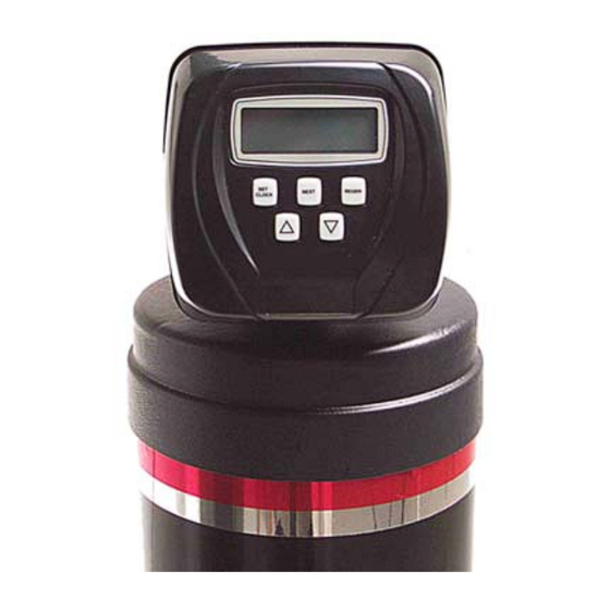
Advanced Water Conditioners
featuring the Custom Control F2CC Valve
OWNER'S MANUAL
FOR ALL FUSION² F SERIES AND FCA SERIES WATER CONDITIONERS
THIS MANUAL IS TO BE LEFT WITH THE OWNER OF THE EQUIPMENT FOR
REFERENCE PURPOSES AND TECHNICAL GUIDANCE.
IT IS STRONGLY
RECOMMENDED
THAT
QUALIFIED
DEALER
SERVICE
PERSONNEL
BE
CONTACTED IN THE EVENT OF AN UNKNOWN INTERRUPTION OF SERVICE OR
APPARENT
PRODUCT
MALFUNCTION.
AN
ANNUAL
PREVENTATIVE
MAINTENANCE INSPECTION BY A WATER PROFESSIONAL IS RECOMMENDED
TO ENSURE TROUBLE-FREE AND CONTINUOUS OPERATION.
www.waterite.com
Waterite Technologies, Inc. ■ 1-885 Keewatin Street, Winnipeg, MB Canada ■ R2X 2S7
Advertisement
Table of Contents

Related Manuals for Waterite FUSION2 F Series


Summary of Contents for Waterite FUSION2 F Series
- Page 1 CONTACTED IN THE EVENT OF AN UNKNOWN INTERRUPTION OF SERVICE OR APPARENT PRODUCT MALFUNCTION. ANNUAL PREVENTATIVE MAINTENANCE INSPECTION BY A WATER PROFESSIONAL IS RECOMMENDED TO ENSURE TROUBLE-FREE AND CONTINUOUS OPERATION. www.waterite.com Waterite Technologies, Inc. ■ 1-885 Keewatin Street, Winnipeg, MB Canada ■ R2X 2S7...
-
Page 2: Table Of Contents
TABLE OF CONTENTS Preinstallation Instructions for Dealer.......inside front cover Specifications.................1 Cycle Sequence Settings..............2 Softener System Setup (programming)...........3-5 Bypass Valve Description & Diagrams..........6 Installation...................7-8 Installer Settings..Hardness, Override, Regen Time & Time of Day......9 Normal Operating & Error Displays, Power Loss....10 Low Salt Warning &... -
Page 3: Specifications
CONTROL VALVE SPECIFICATIONS SERVICE FLOW RATE & PRESSURE LOSS 27 gpm (102.2 lpm) @ 15 psi (103 kPa) ∆ ∆ ∆ ∆ P (valve only, including bypass valve, but not including mineral, etc.) BACKWASH FLOW RATE & PRESSURE LOSS 27 gpm (102.2 lpm) @ 25 psi (172 kPa) ∆... -
Page 4: Cycle Sequence Settings
CYCLE SEQUENCE CYCLE SEQUENCE instructions allows the setting of the order of the CYCLE OPTIONS cycle. There are 9 cycles which can be arranged in any order. BACKWASH DN BRINE FILL Later in this book the INSTALLER SETTINGS allow the setting of how SOFTENING RINSE UP BRINE... -
Page 5: Softener System Setup (Programming)
SOFTENER SYSTEM SETUP In SOFTENER SYSTEM SETUP you choose the duration for the cycles selected in CYCLE SEQUENCE and specify other other operating parameters for the system. The upper and lower limits of the allowable values for the cycles are as follows: CYCLE SETTING LIMITS CYCLE OPTIONS... - Page 6 SOFTENER SETUP DETAIL TABLE This table is to be used as a guide or shortcut to the settings made in Step 3I, 8S, and 9S. For quick programming use the recommended settings shown in row 3 below in bold italic type. Gallons Regeneration Result...
- Page 7 SOFTENER SYSTEM SETUP ∆ Step 8S – Set Gallons Capacity using the button. If value is set to: STEP 8S • “AUTO” ...the gallon capacity will be automatically calculated and reserve capacity will be automatically estimated. • “oFF”...the regeneration will be based on the day override set (see Installer Settings Step 3I).
-
Page 8: Bypass Valve Description & Diagrams
BYPASS VALVE The bypass valve is typically used to isolate the control valve from the plumbing system’s water pressure in order to perform control valve repairs or maintenance. The 1" full flow bypass valve incorporates four positions including a diagnostic position that allows a service technician to have pressure to test a system while providing untreated bypass water to the building. -
Page 10: Installation
INSTALLATION INLET/OUTLET PLUMBING: Connect to a supply line downstream of outdoor spigots. Install an inlet shutoff valve and plumb to the unit’s bypass valve inlet located at the right rear as you face the unit. There are a variety of installation fittings available. -
Page 11: Installer Settings
INSTALLER SETTINGS STEP 1I NOTE: What follows assumes that AUTO is set for regeneration mode in Step 8S, meaning gallons are automatically calculated. ∆ STEP 1I - Press NEXT and simultaneously for 3 seconds. STEP 2I STEP 2I – Hardness: Set the amount of hardness in grains per gallon (default 20) ∆... -
Page 12: Normal Operating & Error Displays, Power Loss
NORMAL OPERATING DISPLAYS GENERAL OPERATION When the system is operating one of three displays will be shown. Pressing NEXT will alternate ß between the displays. One of the displays is the current time of day. Depending the system configura- tion, the second display is one of the following: days remaining or gallons remaining. -
Page 13: Low Salt Warning & Resetting It
LOW SALT WARNING (optional) Salt Remaining or Adding Salt If the Low Salt Warning option was factory installed the following screens will be viewed in the User Display. ß Note: The salt used per regeneration setting was set in increments of 0.1 pounds, but the LBS REMAINING screen will round up or down to the closest whole number. -
Page 14: Start Up Instructions
START UP INSTRUCTIONS • After installation is completed rotate the bypass handles to the bypass position (see bypass valve diagram page ). • Turn on water and check for leaks. • Fully open a cold water faucet. • Allow water to run until clear to rid pipes of debris which may have occurred during installation. •... -
Page 15: Front Cover, Drive Assembly And Piston
REPLACEMENT PARTS Front Cover and Drive Assembly Item No. Part No. Description Qty. V3175CC-01 Front cover assy., CC V3107-1 Motor V3106-01 Drive bracket & spring clip V3108CC PC board, CC V3110 Drive gear, 12x36 V3109 Drive gear cover V3002CC Drive assy., CC not shown V3186 Transformer, 110V-12V... -
Page 16: Injector Assembly & Refill Port Assembly
REPLACEMENT PARTS Injector assembly with Cap, Plug, Screen and O-Ring Item No. Part No. Description Qty. V3176 Injector cap V3152 O-ring 135 V3177 Injector screen V3010-1Z Injector assy. plug V3010-1A A injector assy., BLACK V3010-1B B injector assy., BROWN V3010-1C C injector assy., VIOLET V3010-1D D injector assy., RED... -
Page 17: Drain Line 3/4" Assembly & Flow Controls
REPLACEMENT Drain Line Assembly, 3/4" PARTS Item No. Part No. Description Qty. H4615 Locking clip, elbow PKP10TS8-BULK Insert, 5/8" tube Optional V3192 Nut, æ" drain elbow Optional V3158-01 Drain elbow assy., æ" NPT V3163 O-ring 019 V3159-01 DLFC Retainer assy. V3162-007 0.7 DLFC for æ"... -
Page 18: Drain Line 1" Assembly & Flow Controls
REPLACEMENT Drain Line Assembly, 1" PARTS Item No. Part No. Description Qty. H4615 Locking clip, elbow V3008-02 Drain fitting, 1" straight V3166 Drain fitting body, 1" V3167 Drain fitting adapter, 1" V3163 O-ring 019 V3150 Split ring V3151 Nut, 1" QC V3105 O-ring 215 V3190-065... -
Page 19: Water Meter & Bypass Valve
REPLACEMENT Water Meter and Meter Plug PARTS Item No. Part No. Description Qty. V3151 Nut, 1" QC V3003 Meter assy., includes Items 3 and 4 V3118-01 Turbine assy. V3105 O-ring 215 V3003-01 Meter plug assy. Bypass Valve Item Part No. Description Qty. -
Page 20: Installation Fitting Assemblies & Service Wrench
INSTALLATION FITTING ASSEMBLIES ∫ Description: Fitting " & 1" PVC Solvent Elbow Assembly Description: Fitting 1" PVC Male NPT Elbow Assembly Assembly Part No: V3007, 2 req’d. Assembly Part No: V3007-01, 2 req’d. Item No. 4, Fitting only Part No. V3149, 2 req’d. Item No. -
Page 21: Control Valve Servicing
Service Instructions DRIVE ASSEMBLY Remove the valve cover to access the drive assembly by pulling out slightly on the two tabs centered on the side. Disconnect the power source plug (black wire) from the PC board prior to disconnecting the motor or water meter plugs from the PC board. - Page 22 Replace the motor if necessary. Do not lubricate the motor or the gears. When reinstalling the motor gently turn the motor while inserting so that the gear on the motor meshes with the gears under the drive gear cover and the small plastic bulge engages one of the slots on the motor housing. Reconnect the motor plug to the two pronged jack on the lower left hand side of the PC board.
- Page 23 The regenerant piston (the small diameter one behind the main piston) is removed from the main piston by pressing straight sideways to unsnap it from its latch. Chemically clean in dilute sodium bisulfite or vinegar or replace the regenerant piston if needed. To remove the main piston, fully extend the piston rod by turning the main drive gear counterclockwise, and then unsnap the main piston from its latch by pressing on the numbered side.
- Page 24 Two holes are labeled DN and UP. Check for compliance with one of the following: a. for down flow systems, the appropriate size injector is located in the “DN” hole, a plug is in the “UP” hole and that the piston is a combination of the main piston and the regenerant piston; b.
- Page 25 BYPASS VALVE The working parts of the bypass valve are the rotor assemblies that are contained under the bypass valve caps. Before working on the rotors, be sure that there is a closed shut-off valve ahead of the unit and the system is depressurized. Turn the red arrow shaped handles towards the center of the bypass valve and back to the arrow direction several times to ensure rotor is turning freely.
-
Page 26: Troubleshooting Procedures 1
TROUBLESHOOTING PROCEDURES 1 Problem Cause Solution a. Transformer unplugged a. Reconnect transformer b. No power at outlet b. Repair or use working outlet 1. Timer does not display time of day c. Defective transformer c. Replace transformer d. Defective PC board d. - Page 27 TROUBLESHOOTING PROCEDURES 2 Problem Cause Solution a. Motor not operating a. Replace motor b. No power at outlet b. Repair outlet or use working outle c. Defective transformer c. Replace transformer 6. Valve stalled in regeneration d. Defective PC board d.
Need help?
Do you have a question about the FUSION2 F Series and is the answer not in the manual?
Questions and answers
Which kind of salt should I be using in my Fusion2 — pellet or solar?