
Related Manuals for MEGAFLO Eco Plus 250


Summary of Contents for MEGAFLO Eco Plus 250
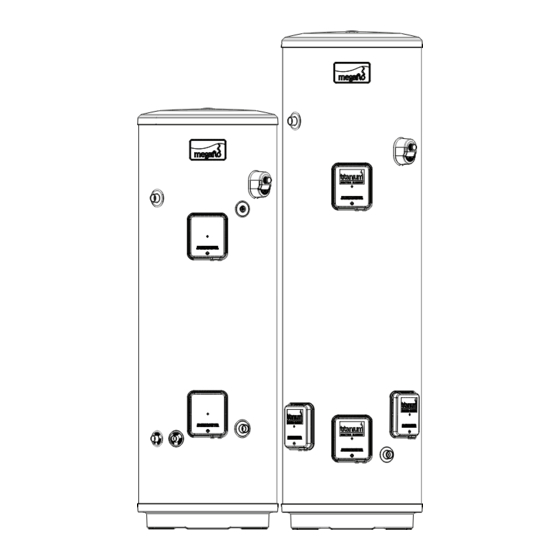
- Page 1 MEGAFLO Eco Plus Unvented Hot Water Cylinders 250L & 300L MEGAFLO Eco Plus Product Guide...
- Page 2 Contents Product Specification ..................................Page 3 Installation and Commissioning Instructions ..........................Page 10 Maintenance and Servicing ................................Page 24 User Guide ......................................Page 33 Unvented Hot Water Cylinder...
- Page 3 • Introduction • Checklist • General Requirements • Water Supply • Power Supply • The Environment • Specification and Dimensions Unvented Hot Water Cylinder...
-
Page 4: Component Checklist
Building Regulation Part L. The MEGAFLO Eco Plus unvented water heater can be fed directly from the cold water mains supply to the property without the need for separate feed cisterns or vent pipes. It is supplied complete with all its necessary inlet and safety controls, electric immersion heater(s) and, for indirect units, a cylinder thermostat, thermal cut-out, 2-port motorised valve and wiring centre. -
Page 5: General Requirements
The insulation set is important to ensure heat and energy conservation. See section 2 (page 16) for more information. To aid installation, the MEGAFLO Eco Plus is provided with lifting points located in the base moulding. The weights of the units are noted on table 2, page 8. -
Page 6: Outlet / Terminal Fittings (Taps, Etc.)
Outlet / Terminal Fittings (Taps, Etc.) The MEGAFLO Eco Plus can be used in conjunction with most types of terminal fittings. It is advantageous in many mixer showers to have balanced hot and cold water supplies, in these instances the balanced cold water supply should be teed off the supply to the MEGAFLO Eco Plus immediately after the cold water combination valve (See Figure 5, page 12). -
Page 7: Specifications And Dimensions
Specifications and Dimensions Outline Specifications Maximum mains water supply pressure (to 3.5 Bar Pressure Reducing Valve) 1.6 MPa (16 bar) Operating pressure (Pressure reducing valve set pressure – non adjustable) 0.35 MPa (3.5 bar) Pressure Relief Valve 0.8 MPa (8 bar) Temperature / Pressure Relief Valve set temp / pressure 90ºC / 1MPa (10 bar) Immersion heater rating (a.c. - Page 8 Figure 2 - Indirect Dimensions 30° 27° 47° 45° Table 2 - Dimensions TYPE DIMENSIONS (mm) WEIGHTS (kg) SIZE DIRECT INDIRECT EMPTY FULL 250L 1737 1366 1322 250L 1441 1321 1737 1366 2052 1681 1573 300L 2052 1755 373 300L 1681 1635 Table 3 - Indirect Units - Indirect Coil Ratings...
- Page 9 Figure 3 - Direct Dimensions 55° 30° 45° Table 5 - Direct Units - Heat up times HEAT-UP TIMES NOMINAL CAPACITY MAXIMUM HEAT-UP (LITRES) TIME (mins) 65.6 78.7 Times based on nominal volume Times based on a 45°C temperature rise NOTE Coil heating performance based on a primary flow rate of 15L/min at 80°C.
- Page 10 • General Installation • Indirect Model • Direct Model • Commissioning Unvented Hot Water Cylinder...
-
Page 11: General Installation
(stamped on the side of the brass body) pointing towards the MEGAFLO Eco Plus heater. If a balanced pressure cold water supply is required to a thermostatic shower mixer valve this may be teed off the supply to the MEGAFLO Eco Plus immediately after the 3.5 Bar Pressure Reducing Valve (See Figure 5, page 12). - Page 12 Figure 5 - Schematic Installation diagram using 3.5 bar pressure reducing valve in conjunction with 8 bar pressure relief valve Unvented Hot Water Cylinder...
- Page 13 Drain Tap A drain tap should be installed in the cold water supply to the MEGAFLO Eco Plus unit between the 8 Bar Pressure Relief Valve and the heater at as low a level as possible (see Figure 1, page 5). It is recommended that the outlet point of the drain pipe work be at least 1 metre below the level of the heater (this can be achieved by attaching a hose pipe to the drain tap outlet spigot).
- Page 14 T&P Relief Valve Insulation A set of insulating components is supplied with the MEGAFLO Eco Plus water heater and should be installed to gain maximum heat and energy saving benefits. See Figure 7 (below), for installation instructions. Warnings i) Under no circumstances should the factory fitted Temperature /Pressure Relief Valve be removed other than by authorised Heatrae Sadia personnel.
- Page 15 The following extract is taken from the latest G3 Regulations Discharge pipes from safety devices Discharge pipe D1 3.50 Safety devices such as temperature relief valves or combined temperature and pressure and pressure relief valves (see paragraphs 3.13 or 3.18) should discharge either directly or by way of a manifold via a short length of metal pipe (D1) to a tundish. 3.51 The diameter of discharge pipe (D1) should be not less than the nominal outlet size of the temperature relief valve.
- Page 16 Discharge Pipework It is a requirement of Building Regulations that any discharge from an unvented system is conveyed to where it is visible, but will not cause danger to persons in or about the building. The tundish and discharge pipes should be fitted in accordance with the requirements and guidance notes of Building Regulations.
-
Page 17: Indirect Model
MUST be pumped. Gravity circulation will not work due to the special design of the primary heat exchanger. It is recommended that an air bleed point or automatic air vent is incorporated in the primary return pipework close to the MEGAFLO Eco Plus unit. The boiler flow temperature should usually be set to 82ºC (maximum flow temperature to primary heat exchanger 89ºC). - Page 18 The MEGAFLO Eco Plus indirect units are supplied with an immersion heater which can be used as an alternative heat source should the boiler supply need to be isolated from the MEGAFLO Eco Plus unit. The immersion heater is located within the controls housing. Refer to Secion 2, page 20 “Wiring and Operation”...
- Page 19 Figure 11 - 2 port valve in conjunction with a 3 port mid-position valve system (“Y” Plan) MEGAFLO ECO INDIRECT THERMAL CONTROLS MEGAFLO ECO (DHW) 2-PORT PROGRAMMER (SUPPLIED FITTED) VALVE (SUPPLIED) Bl Br G O GY BLUE BROWN GREY ORANGE...
-
Page 20: Direct Model
Direct Model Immersion Heater(s) The MEGAFLO Eco Plus is supplied with four factory fitted immersion heaters. Each immersion heater is rated 3kW at 240V. Unvented Hot Water Cylinder To remove the immersion heater: Open the cover to the immersion heater. Unplug the two connecting wires to the element and gently remove the two capillary tubes from the stat pocket, the control capillary comes out first and then the cut-out . - Page 21 DO NOT BYPASS THE THERMAL CUT-OUT(S) IN ANY CIRCUMSTANCES DISCONNECT FROM THE MAINS SUPPLY BEFORE REMOVING ANY COVERS NEVER ATTEMPT TO REPLACE AN IMMERSION HEATER OTHER THAN WITH THE RECOMMENDED HEATRAE SADIA MEGAFLO Eco Plus SPARE PART Figure 13 - Schematic wiring diagram - Direct immersion heaters with adjustment details Direct Wiring Layout 1.5mm²...
- Page 22 When the primary circuit is full return the lever to the AUTO position. Vent any trapped air by opening the air bleed. Switch on the boiler, ensure the programmer is set to Domestic Hot Water. Allow the MEGAFLO Eco Plus unit to heat up and check that the indirect thermostat and 2-port motorised valve operate correctly.
- Page 23 Notes Unvented Hot Water Cylinder...
- Page 24 • Maintenance • Fault Finding • Servicing • Spares • Benchmark • Spares stockists Unvented Hot Water Cylinder...
- Page 25 MEGAFLO Eco Plus unit. Attach a hosepipe to the drain cock having sufficient length to take water to a suitable discharge point below the level of the unit, at least one metre below the unit is recommended. Open hot water tap nearest to the MEGAFLO Eco Plus to relieve the system pressure.
-
Page 26: Fault Finding
The Fault Finding chart (Table 7 below) will enable operational faults to be identified and their possible causes rectified. Any work carried out on the MEGAFLO Eco Plus unvented water heater and its associated controls MUST be carried out by a competent installer for unvented water heating systems. - Page 27 Spares Spare parts A full range of spare parts are available for the MEGAFLO Eco Plus range. Refer to the Technical Data label on the unit to identify the model installed and ensure the correct part is ordered. Description Part no.
- Page 28 Figure 16: Indirect Exploded View Indirect Control Assembly Direct Combined Mounting plate (indirect) Thermostat and 95:607:931 Thermal Cut-Out Indirect Combined Thermostat and 95:612:717 Thermal Cut-Out 95:612:716 Terminal cover (indirect) 95:614:118 Backnut 95:607:940 Gasket 95:611:822 Incoloy Immersion Heater Lower 6 Way Terminal Block 95:606:984 95:607:933 Unvented Hot Water Cylinder...
- Page 29 Figure17: Direct Exploded View Direct Control Assembly Terminal Cover (direct) 95:614:119 Mounting Plate 95:607:929 95:612:717 Titanium Immersion Heater - Upper Backnut 95:606:989 Gasket 95:607:940 95:611:822 3 Way Terminal Block 95:607:932 Spare components are common to Upper and Lower Direct Control Assemblies Exept for the Upper element 95:606:989 and Lower element 95:606:988 Titanium Immersion...
- Page 30 Benchmark logbook Unvented Hot Water Cylinder...
- Page 31 Unvented Hot Water Cylinder...
- Page 32 Spares Stockists Electric Water Heating Co. 2 Horsecroft Place Pinnacles Harlow Essex CM19 5BT Tel: 0845 0553811 E-Mail: sales@ewh.co.uk Special Product Division Units 9 & 10 Hexagon Business Centre Springfield Road Hayes Middlesex UB40 0TY Tel: 0208 5730574 Parts Center Network 65 Business Park Bentley Wood Way Burnley...
- Page 33 • User Instructions • Guarantee • Customer Service Unvented Hot Water Cylinder...
- Page 34 Direct Megaflo Eco Plus Supplier’s name or trade mark Supplier’s model identifier Storage volume V in litres 250.0 300.0 Mixed water at 40 °C V40 in litres The declared load profile The water heating energy efficiency class of the model The water heating energy efficiency in % 38.5...
- Page 35 NOTES. Unvented Hot Water Cylinder...
-
Page 36: User Instructions
Indirect units are fitted with an Indirect Thermostat which controls a 2-port motorised valve and hence the temperature of the water in the MEGAFLO Eco Plus unit. The thermostat is factory set to give a water storage temperature of approx. 60ºC, however it can be set to control between 12ºC and 68ºC, this will usually have been done during installation. - Page 37 • The MEGAFLO product has not been modified or tampered with in any way, other than by a Heatrae Sadia or Baxi Customer Support approved engineer.
- Page 38 Baxi Group Baxi Customer Support approved engineer in accordance with the requirements set out in the maintenance section of the installation instructions. • Access is available, at reasonable times and upon reasonable notice, to the MEGAFLO product to allow for any inspection repair or replacement.
- Page 39 Please contact Baxi Customer Support on 0844 871 1535 for details. *In domestic† properties, lifetime is the period during which the first owner of the MEGAFLO or new build home continues to own the property. Should the property be sold, the new owner and any subsequent owners will receive a 30 year warranty from the date the original owner purchased the MEGAFLO or new home with a MEGAFLO installed.
-
Page 40: Customer Service
Customer service Telephone: Megaflo 0344 8711535 Hurricane Way Norwich Facsimile: Norfolk 0344 8711528 NR6 6EA E-mail: megafloservice@heateam.co.uk 36006172_issue _07...
Need help?
Do you have a question about the Eco Plus 250 and is the answer not in the manual?
Questions and answers