Table of Contents
Advertisement
PROFESSIONAL INSTALLATION RECOMMENDED!
This equipment is similar to other gate or door equipment and meets or exceeds
Underwriters Laboratory Standard 325 (UL 325). However, gate equipment has
hazards associated with its use and therefore by installing this product the installer
and user accept full responsibility for following and noting the installation and
safety instructions. Failure to follow installation and safety instructions can result
in hazards developing due to improper assembly. You agree to properly install this
product and that if you fail to do so Gates That Open, LLC, ("GTO") shall in no event
be liable for direct, indirect, incidental, special or consequential damages or loss of
profits whether based in contract tort or any other legal theory during the course
of the warranty or at any time thereafter. The installer and/or user agree to assume
responsibility for all liability and use of this product releasing Gates That Open, LLC,
from any and all liability. If you are not in agreement with this disclaimer or do not
feel capable of properly following all installation and safety instructions you may
return this product for full replacement value.
READ ALL INSTRUCTIONS CAREFULLY AND COMPLETELY before attempting to
install and use this automatic gate operator. This gate operator produces a high level
of force. Stay clear of the unit while it is operating and exercise caution at all times.
All automatic gate operators are intended for use on vehicular gates only.
This product meets and exceeds the requirements of UL 325, the standard which
regulates gate operator safety, as established and made effective March 1, 2000, by
For more information on the GTO/ACCESS SYSTEMS full line of automatic gate
operators and access controls visit our website at www.gtoaccess.com.
©2011 Gates That Open, LLC
Installation Manual for the
PROFESSIONAL RESIDENTIAL
4000XLS
4000XLS
SINGLE Gate Operator System
WARNING!
Underwriters Laboratories Inc.
Printed in China for Gates That Open, LLC.
ACCESS
SYSTEMS
®
, LLC
R4854 01.10.12
Advertisement
Table of Contents

Related Manuals for GTO Access Systems 4000XLS


Summary of Contents for GTO Access Systems 4000XLS
- Page 1 You agree to properly install this product and that if you fail to do so Gates That Open, LLC, (“GTO”) shall in no event be liable for direct, indirect, incidental, special or consequential damages or loss of profits whether based in contract tort or any other legal theory during the course of the warranty or at any time thereafter.
-
Page 2: Class Rating
Please record the following information product serial number (located on right side of control box), be sure to keep all receipts for proof of purchase. Refer to this information when calling GTO for service or assistance with your automatic gate opener. -
Page 3: Table Of Contents
Table of Contents Class Rating ........................inside cover Please Read This First ..........................ii Important Safety Instructions......................iii Technical Specifications ........................1 Before You Begin..........................2 Determine Charging Option for Battery: Transformer OR Solar ......... 2 Solar Panel and Gate Activity Chart ..................2 Check Direction of Gate Swing .................... -
Page 4: Please Read This First
(or keypad, etc.) again. Please call GTO at (800) 543-GATE [4283] or (850) 575-0176 for more information about our GTO/ACCESS SYSTEMS professional line of gate operators and accessories. Our Sales Department will be glad to give you the name and phone number of a GTO/ACCESS SYSTEMS dealer near you. -
Page 5: Important Safety Instructions
Because GTO automatic gate operators are only part of the total gate operating system, it is the responsibility of the installer/consumer to ensure that the total system is safe for its intended use. - Page 6 Zone 3 – the path of the gate. Zone 4 – the space between the gate in the open position and any object such as a wall, fence, etc. Zone 5 – pinch points between the operator and gate. GTO 4000XLS Instruction Manual © 01.10.12...
- Page 7 If any of these signs or warning decals become damaged, illegible or missing, replace them immediately. Contact GTO for free replacements. 2. The gate is automatic and could move at any time, posing a serious risk of entrapment. No one should be in contact with an activated gate when it is moving or stationary.
-
Page 8: Required Safety Precautions For Gates
7. To operate this equipment safely, YOU must know how to disconnect the operator for manual gate operation (page iii). If you have read the instructions and still do not understand how to disconnect the operator, contact the GTO Service Department. -
Page 9: Secondary Means Of Protection Against Entrapment
A wireless contact sensor shall function under the intended end-use conditions. You may want to consider adding photo beams to your installation. GTO Photo Beams [R4222] provide a “non contact” means of entrapment protection. - Page 10 Warning signs (2 enclosed) to be installed on each side label (1) installed on right side of control box. of the gate (3–5 feet above the bottom of the gate). Logo and warning labels (2) installed on each side of operator housing. viii GTO 4000XLS Instruction Manual © 01.10.12...
-
Page 11: Technical Specifications
Technical Specifications GTO/ACCESS SYSTEMS 4000XLS AUTOMATIC GATE OPERATOR DRIVE • Low friction screw drive (linear actuator) rated for -5 ºF to +160 ºF (-21 ºC to +71 ºC). Use of GTO battery heater FM316 (Not solar compatible) is recommended in extreme cold temperatures. • Powered by a 12 V motor with integral case hardened steel gear reducer. Motor speed reduced to 375 rpm. • Maximum opening arc of 110º. Approximate opening time (90º): 16-20 seconds, depending on weight of gate. POWER • The system is powered by a 12 Vdc, 7.0 Ah, sealed, rechargeable acid battery. • Battery charge is maintained by a 120 Vac, 18 Vac output transformer. Blade-style control board fuse is rated for 25 A. NOTE: The transformer should not be directly connected to any battery. Do not replace fuses with higher ampere rated fuses;... -
Page 12: Before You Begin
NOTE: A minimum of 10 watts solar charging power is needed to charge the batteries. Adding a second battery [RB500] will improve the number of gate cycles. 10 Watt Solar Panel [FM123] 5 Watt Solar Panel [FM122] GTO 4000XLS Instruction Manual © 01.10.12... -
Page 13: Check Direction Of Gate Swing
If installed correctly, a grounding system will 8 Foot Ground Rod help minimize damage to your 5/8” Copper Clad Steel (not included) gate opener. - available at local homecenter and hardware stores - GTO 4000XLS Instruction Manual © 01.10.12... -
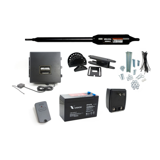
Page 14: 4000Xls Parts List
3/8" x 3-3/4" Bolt (2) 3/8" Washer (3) 3/8" x 3-1/2" Clevis Pin (1) 3/8" Lock Nut (2) 3/8" x 1-3/4" Clevis Pin (1) Hairpin Clip (2) 3/8" x 1/2" Bushing (2 ) 3/8" x 3/16" Bushing (2) GTO 4000XLS Instruction Manual © 01.10.12... -
Page 15: Tools Needed
• The diameter of the post should be at least 6” in order to mount the post bracket. (Page 6) • Depending upon the diameter of the post, you may need longer bolts than those provided. Bolts should be at least 1” longer than the diameter of the post. (Page 6) • Metal plate for wooden posts. (Page 6) • A horizontal or vertical cross member or mounting plate may be needed to mount the operator to the gate. (Page 3) • Some types of installations require U-Bolts. (Page 10) • Surge protection for transformer. (Page 15) • Weatherproof cover for transformer if installed outside. (Page 15) • For push-to-open applications you must have PTO Bracket [R4KPTO). (Page 21). GTO 4000XLS Instruction Manual © 01.10.12... -
Page 16: Installation Overview
• A post smaller than 6” in diameter should be made of metal instead of wood so that it will remain stable while the operator is moving the gate. • Masonry columns will require masonry anchors/ hardware (not provided). GTO 4000XLS Instruction Manual © 01.10.12... - Page 17 Insert ” x 3 ” hex head 3/8" Washer bolt and washer through post pivot bracket and post bracket and secure with ” washer, and lock nut. 3/8" Lock Nut Post Pivot Bracket GTO 4000XLS Instruction Manual © 01.10.12...
-
Page 18: Check Clearance
2“ of clearance between the gate and the operator in both the open and closed positions. This clearance will give the operator the most efficient leverage point for opening and closing the gate and, more importantly, provides the least possible pinch area. Clamp GTO 4000XLS Instruction Manual © 01.10.12... -
Page 19: Install Gate Bracket
Pin Lock [FM345] . Verify that the operator is level, bolts are tight, and Clevis Pin, Bushing, and Hairpin Clip adjust the post bracket assembly if necessary. Fence Post GTO 4000XLS Instruction Manual © 01.10.12... -
Page 20: Install Closed Position Stop Plate
TOP VIEW wood gates, etc.). This hardware is not provided. Step 12 Return gate to the open position and reattach operator to gate. Closed Position Stop Plate Gate In Closed Position GTO 4000XLS Instruction Manual © 01.10.12... -
Page 21: Mount The Control Box And Receiver
If attaching receiver to metal fence, you should mount receiver on a piece of wood attached to the fence (see illustration). The receiver cable: • Cable length is 10 ft. (receivers with longer cables are available as special order items; call the GTO Sales Department). • NEVER splice receiver cable! • Run the receiver cable through PVC conduit to protect it from damage. -
Page 22: Connect Operator Power Cable
RECEIVER CONTROL INPUTS MASTER OPERATOR BLUE COM COM MASTER OPERATOR RECEIVER Wrong Wrong Correct Wire Screwed into Exposed strands wire insulation of wire Power Cable from the Master Arm GTO 4000XLS Instruction Manual © 01.10.12... -
Page 23: Connect The Power Input
Pull 6” to 8” of wire into the control box. Power Cable from Low Voltage Wire from Transformer Master Arm or Solar Panel PVC Pipe GTO 4000XLS Instruction Manual © 01.10.12... -
Page 24: Connect Battery
PLUGGED INTO AN OUTLET DURING STEP 3 (page 15)! Connect Battery Step 1 Make sure the control box power switch is OFF. Remove the control box cover and slide the battery into position (terminals to the right). ON/OFF Switch GTO 4000XLS Instruction Manual © 01.10.12... -
Page 25: Control Board Settings
LEARN MAST LIMIT button for 5 the fully OPEN seconds. This will clear the memory for the closed position. limit position. Repeat Steps 1-5. GTO 4000XLS Instruction Manual © 01.10.12... -
Page 26: Adjust The Stall Force Setting
3 to 120 seconds. Adjust the Auto-Close potentiometer by using a small flat blade screwdriver. AUTO CLOSE TIME STALL FORCE STATUS LEARN RMT SOFT START OFF WARNING LEARN OPEN PULL PUSH MAST LIMIT 2ND OPEN DLY. SIMULT. MODE1 Auto Close Time MODE2 Potentiometer LEARN 2ND LIMIT GTO 4000XLS Instruction Manual © 01.10.12... -
Page 27: Program Your Personal Transmitter Setting
Program Your Personal Transmitter Setting All GTO transmitters are set to a standard code at the factory and are ready to operate your GTO gate operator. For your safety and security, we strongly recommend that you replace the factory setting with your own personal setting. -
Page 28: Dip Switch Settings
To-Open bracket (see Push-To- Open Instructions on page 21). DIP Switch #4: Dual Operation ON– Second opens simultaneously with master. OFF– Second opens after master (factory preset). Note: Not applicable for single gate operator. GTO 4000XLS Instruction Manual © 01.10.12... -
Page 29: Connecting Accessories
6 CLOSE EDGE: (Typically for use with safety edge device) • Activation of this input while the gate is closing will cause the gate to stop and reverse direction for approximately 2 seconds. • Activation of this input while the gate is opening has no effect (gate will continue to open). • Activation of this input while gate is idle will prevent gate from closing. 7 OPEN EDGE: (Typically for use with safety edge device) • Activation of this input while the gate is opening will cause the gate to stop and reverse direction for approximately 2 seconds. • Activation of this input while the gate is closing has no effect (gate will continue to close). • Activation of this input while gate is idle will prevent gate from opening. GTO 4000XLS Instruction Manual © 01.10.12... -
Page 30: Wiring Accessories
NOTE: Connections are for typical applications. Digital Keypad There may be additional connection options for applications that are not illustrated here. Connecting Other Auxiliary Devices (Sirens, Lights, etc.) • These 2 terminals are normally open “dry-contact” (no voltage) relay ouput. • Relay is closed when the gate is in motion; Relay is open when the gate is not in motion. • These 2 terminals maximum rating is 24Vdc, 1 Amp. GTO 4000XLS Instruction Manual © 01.10.12... -
Page 31: Push-To-Open Installation
Push-To-Open Post Pivot Bracket (R4KPTO) " *The Troubleshooting Wizard has detailed information on Gate in the Open Position Push-To-Open installations. Pinch Area 2" minimum Clamp Gate in the Closed Position Pinch Area 2" minimum GTO 4000XLS Instruction Manual © 01.10.12... -
Page 32: Setting The Open Position Limit (Push-To-Open Installations)
LEARN MAST LIMIT button for 5 CLOSED position. Gate open position seconds. This will clear the memory for the open is now programmed Control Gate is now limit position. Repeat Steps 1-5. programmed GTO 4000XLS Instruction Manual © 01.10.12... -
Page 33: Column Installation
Gate Column Column Mount Example (A + B can not exceed 19 inches) Pivot Bracket Example: If A is 8" then B cannot exceed 11" *The Troubleshooting Wizard has detailed information on column mounting. GTO 4000XLS Instruction Manual © 01.10.12... -
Page 34: Troubleshooting Guide
Troubleshooting Guide If your gate operator does not function properly after it is installed, use this guide before calling the GTO Service Department. Generation 3 Audible Feedback SYMPTOM DIAGNOSIS CHECK: 1 short beep upon Circuit Board • Normal Operation power up Powered Up &... -
Page 35: Voltage Readings
12.5 to 13.5 Vdc or Two 12V, 7 amp hour Batteries if using solar power Measure voltage at battery terminals with battery disconnected Charging circuit 12.0 to 14.8 Vdc Measure voltage at battery terminals with battery connected GTO 4000XLS Instruction Manual © 01.10.12... -
Page 36: Repair Service
2. Use the 24/7 Troubleshooting Wizard at http://support.gtoinc.com. 3. If you are unable to solve the problem, call the GTO Service Department at (800) 543-1236, or (850) 575-4144. Refer to the serial number (located on the right side of the control box) and date of purchase when calling for assistance. -
Page 37: Accessories
This specially designed wire is UV treated, PVC coated, and ready for direct burial. Solar Panel Kits [FM122/FM123] If your gate operator is more than 1000 ft. away from an AC power outlet, you can choose to maintain the battery charge with the GTO Solar Panel Kit. • 10 Watt Solar Panel Charging Kit [FM123] • 5 Watt Solar Panel Charging Kit [FM122] Additional/Replacement Battery [RB500] For additional battery power or replacement. - Page 38 LOCKING & SECURITY ACCESSORIES Automatic Gate Lock [FM144/FM142] The #1 Accessory For Swing Gate Operators! Designed for added security in conjunction with GTO Automatic Gate Operators. The gate lock unlocks and locks automatically when the gate opens and closes. The perfect solution for high wind conditions. Bulldog Pedestrian Gate Lock [FM145] Designed to mount on horizontal swing “walk through”...
- Page 39 (pull to open). Order two brackets for a dual swing gate installation. Column Mount Lock Receiver [433IH] For use with the Automatic Gate Lock or Bulldog Pedestrian Gate Lock when mounting on brick columns or applications with limited space. GTO 4000XLS Instruction Manual © 01.10.12...
- Page 40 ACCESS SYSTEMS PROFESSIONAL RESIDENTIAL 3121 Hartsfield Road • Tallahassee, Florida, USA 32303 (850) 575-0176 • Fax (850) 575-8912 Web site www.gtoaccess.com 24/7 Troubleshooting Wizard: http://support.gtoinc.com...
Need help?
Do you have a question about the Access Systems 4000XLS and is the answer not in the manual?
Questions and answers