Magikitch'n MKG24 Technical & Service Manual
All options
Hide thumbs
Also See for MKG24:
- Installation & operation manual (24 pages) ,
- Installation and operation instruction manual (7 pages) ,
- Installation and operation instructions manual (25 pages)
Table of Contents
Advertisement
Technical Service Manual
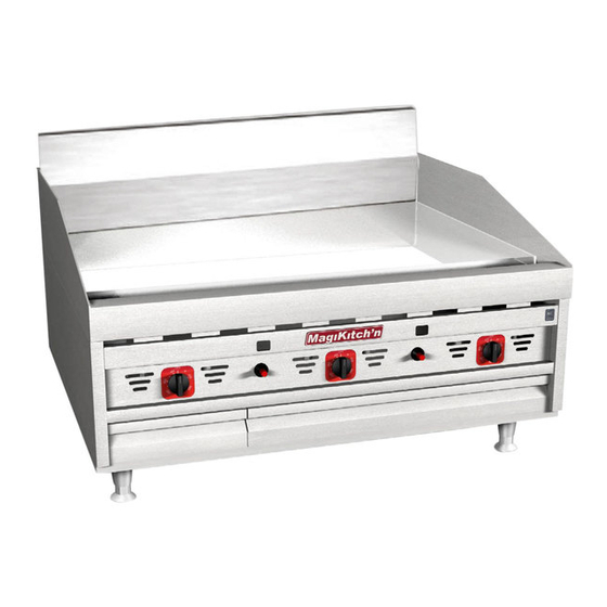
MKG24, MKG36, MKG48, MKG60 & MKG72
Electric Or Solid State Thermostat
Models
All Options
Built After August 1, 2005
E S I G
D
N
D
C
E
E
I
R
F
T
I
L22-296 Rev 0 (4/08)
IMPORTANT FOR FUTURE REFERENCE
Please complete this information and retain this manual
for the life of the equipment:
Model #: ___________________________
Serial #: ___________________________
Date Purchased: ____________________
Snap Action Thermostat
C
E T
R
I
F E D
I
Advertisement
Table of Contents

Related Manuals for Magikitch'n MKG24


Summary of Contents for Magikitch'n MKG24
- Page 1 Model #: ___________________________ Serial #: ___________________________ Date Purchased: ____________________ Technical Service Manual Models MKG24, MKG36, MKG48, MKG60 & MKG72 All Options Built After August 1, 2005 Electric Or Solid State Thermostat Snap Action Thermostat E S I G...
- Page 2 Technical Service Manual MKG Series Gas Griddles WARNING Post This appliance is intended for professional use only and in a prominent location the should be operated by fully trained and qualified instructions to be followed in the event that personnel. an operator smells gas.
-
Page 3: Table Of Contents
Technical Service Manual MKG Series Gas Griddles TABLE OF CONTENTS OVERVIEW...........................4 ..........................4 NTRODUCTION 1.1.1 All models...............................4 1.1.2 Snap Action Models ..........................4 1.1.3 Matchless Models...........................4 ..................4 NSTALLATION PERATION AND LEANING ..........................4 PECIFICATIONS 1.3.1 Gas Information............................4 1.3.2 Elevation Orifice Chart ...........................4 1.3.3 Electrical Information..........................4 THEORY OF OPERATION ....................5... -
Page 4: Overview
Technical Service Manual MKG Series Gas Griddles Overview INTRODUCTION 1.1.1 All models All models are equipped with pilot safety • system, spark enabled pilots, temperature REMOVE controls for each 12” zone, heated by two GREASE BOX 15,000 Btu burners. Temperature sensing probes are embedded into the plate between each pair of burners. -
Page 5: Theory Of Operation
Technical Service Manual MKG Series Gas Griddles HEATING SYSTEM –MATCHLESS Theory Of Operation IGNITION SERIES (E / ST) This section will demonstrate the basic sequence of • Start up of Unit, (See Photo(s) 2, and 2a): operation for Snap Action and Matchless (E/ST) Open the shut off valve (C) Ignition series. -
Page 6: Temperature Control Systems
Technical Service Manual MKG Series Gas Griddles Notice: Once pilots ignite, the ignition modules will • Matchless Ignition (E/ST) models have flame send power to the burner valves, traveling first proving park ignition systems. An external power through the thermostat control, then through the supply is required on these models. -
Page 7: Matchless (St) Series
Technical Service Manual MKG Series Gas Griddles Tightly hold the thermostat shaft (A) and turn Hold knob firmly in place and loosen the 5/16” • • the adjustment screw (B) in small increments to retaining nut (A) with an appropriate socket or shift temperature (1/4 turn is approximately nutdriver (B), See Photo 8. -
Page 8: Matchless Series (E & St)
Technical Service Manual MKG Series Gas Griddles Release the panel clip from the grease box • compartment by twisting the clip out of the slot in the roof of the compartment, See Photo 12. Photo 9 Photo 12 See Photo 10, Using needle nose pliers, •... -
Page 9: Pilot / Ignition System Check
Technical Service Manual MKG Series Gas Griddles PILOT / IGNITION SYSTEM CHECK If no spark is produced, replacement of the • 4.2.1 Ignitor Check- Snap Action Series Piezo ignitor may be required. To Replace remove the ignition wire from the •... -
Page 10: Insufficient Or Absence Of Flame
Technical Service Manual MKG Series Gas Griddles 4.2.4 Pilot Lock-in: Snap Action Series If no spark is evident, check for 115 VAC to the • ignition module between terminal L1 and chassis ground, also verify all other ground If a sufficient pilot flame is present, but the connections, See Photo 17. -
Page 11: Pilot Assembly Replacement
Technical Service Manual MKG Series Gas Griddles Remove the Ignition wire (C), and loosen gas • line fitting (B) prior to removing mounting screws (A). The screws will stabilize the pilot assembly during this procedure. Once screws are removed, pull pilot assembly •... -
Page 12: Orifice/Fuel Type Conversion
Technical Service Manual MKG Series Gas Griddles ORIFICE/FUEL TYPE CONVERSION If Converting Fuel Type, continue here: Poor performance may be an indication of a Change orifices as described in section 4.6.1. • clogged or damaged burner orifice that needs Change pilot assembly, see section 4.4. •... -
Page 13: Gas Pressure Adjustment
Technical Service Manual MKG Series Gas Griddles GAS PRESSURE ADJUSTMENT With the screws removed, the pilot cover plate • Before checking the operating pressure of the and the burner seal plate can be easily appliance, the incoming supply pressure to the removed from the front and set aside. -
Page 14: Temperature Controls Check
Technical Service Manual MKG Series Gas Griddles TEMPERATURE CONTROLS CHECK If voltage is not present and the pilots are • operating, verify 115 VAC output voltage from 4.9.1 Snap-Action Models MV1 terminal(D) on the ignition module, See Photo 32. If there is no voltage at MV1, refer to If there is no burner response when the Section 4.3. -
Page 15: Temperature Probe Check
Technical Service Manual MKG Series Gas Griddles Ohms from the chart value, replace the probe, Turn the control to the maximum temperature • refer to Section 4.10.4. setting, Using a voltmeter, check for 115 VAC 4.9.5 Resistance Chart: Solid State across the blue wire(A), and white wire(B) Thermistor Probe terminals. -
Page 16: 4.10.2 Matchless "E" Models
Technical Service Manual MKG Series Gas Griddles exposed screws(A) found under the knob, See Photo 37. NOTE: If necessary, the thermostat mounting bracket can be carefully dismounted to allow additional access to the controls. Install replacement thermostat in the reverse •... -
Page 17: Thermistor Probe Replacement
Technical Service Manual MKG Series Gas Griddles 4.10.4 Thermistor Probe Replacement Slide the retention plate up to the “V” bracket • and align the mounting holes and secure with The Solid State control has a separate temperature “New” self tapping screws if available. sensing probe, the thermistor probe can be 4.11 SAFETY VALVE REPLACEMENT removed without removing the Solid State control. - Page 18 Technical Service Manual MKG Series Gas Griddles Disconnect the power cord from the electrical • supply, and shut of the gas supply at the manual shutoff valve(C, Photo 2a). • Disconnect outlet(A) gas connection(s) and the pilot gas outlet(B), See photo 42. Disconnect wiring(C) from each solenoid coil.
-
Page 19: Troubleshooting Guide
Trouble Shooting Guide MKG Series Gas Griddles TROUBLESHOOTING GUIDE TROUBLESHOOT GUIDE -SNAP ACTION MODELS Problem Cause Corrective Action 1. Check that all gas connections are turned 1. No gas supply. on, and verify gas pressure at the regulator. 2. No pilot flame. 2. -
Page 20: Troubleshoot Guide - E / St Series
Troubleshooting Guide MKG Series Gas Griddles TROUBLESHOOT GUIDE - E / ST SERIES Problem Cause Corrective Action 1. Appliance power cord, Check power at wall outlet, check appliance fuse. 1. No electrical power. 2. Refer to “Pilot Lock-in” section of manual. 2. -
Page 21: Schematic: Matchless "E" Series
Trouble Shooting Guide MKG Series Gas Griddles SCHEMATIC: MATCHLESS “E” SERIES PP10439 115V, 50-60Hz NEMA 5-15P FRAME J/P1-2 LEFT ON/OFF MV1 LEFT MAIN VALVE PILOT OK J/P1-4 HEAT J/P1-3 TEMP CONTROL LEFT ON/OFF PILOT VALVE IGNITION J/P1-1 MODULE GRN/Y BGND RIGHT ON/OFF RIGHT... -
Page 22: Schematic: Matchless "St" Series
Troubleshooting Guide MKG Series Gas Griddles SCHEMATIC: MATCHLESS “ST” SERIES PP10439 115V, 50-60Hz NEMA 5-15P FRAME J/P1-2 LEFT ON/OFF MV1 LEFT 120(9) COM (8) MAIN VALVE PILOT OK 240(10) J/P1-4 NO (7) HEAT COM (6) J/P1-3 TEMP CONTROL LEFT ON/OFF PILOT VALVE SET POINT IGNITION... -
Page 23: Schematic: Matchless Single Power Switch "E" Series
Trouble Shooting Guide MKG Series Gas Griddles SCHEMATIC: MATCHLESS SINGLE POWER SWITCH “E” SERIES PP10439 115V, 50-60Hz NEMA 5-15P FRAME J/P1-2 J/P4-2 MV1 LEFT MAIN VALVE J/P1-4 J/P4-7 HEAT J/P4-3 J/P1-3 TEMP CONTROL ON/OFF J/P1-1 PILOT VALVE IGNITION J/P4-1 GRN/Y MODULE BGND MV1 RIGHT... -
Page 24: Schematic: Matchless Single Power Switch "St" Series
Troubleshooting Guide MKG Series Gas Griddles SCHEMATIC: MATCHLESS SINGLE POWER SWITCH “ST” SERIES PP10439 115V, 50-60Hz NEMA 5-15P FRAME J/P1-2 J/P4-2 MV1 LEFT 120(9) COM (8) MAIN VALVE 240(10) J/P1-4 NO (7) J/P4-7 HEAT COM (6) J/P4-3 J/P1-3 TEMP CONTROL ON/OFF SET POINT J/P1-1... - Page 25 Trouble Shooting Guide MKG Series Gas Griddles Notes: L22-296 Rev 0 (4/08) Page 25...
-
Page 26: L22-296 Rev
In the event of problems with or questions In the event of problems with or about your order, please contact the questions about your equipment, please MagiKitch’n factory at: contact the MagiKitch’n Authorized (800) 258-3708 US and Canada only or Service and Parts representative (ASAP) (603) 225-6684 World Wide covering your area, or contact MagiKitch’n...
Need help?
Do you have a question about the MKG24 and is the answer not in the manual?
Questions and answers