Panasonic PT-AE1000E Operating Instructions Manual
Hide thumbs
Also See for PT-AE1000E:
- Remote control operating manual (16 pages) ,
- Operating instructions manual (28 pages) ,
- Service manual (82 pages)

Related Manuals for Panasonic PT-AE1000E


Summary of Contents for Panasonic PT-AE1000E
-
Page 1: Lcd Projector
LCD Projector Operating Instructions PT-AE1000E Model No. Before operating this product, please read these instructions carefully and save this manual for future use. TQBJ0206... -
Page 2: Important Safety Notice
We hope it will help you to get the most out of your new product, and that you will be pleased with your Panasonic LCD projector.The serial number of your product may be found on its bottom. You should note it in the space provided below and retain this booklet in case service is required. - Page 3 Important Safety Notice IMPORTANT: THE MOULDED PLUG (U.K. only) FOR YOUR SAFETY, PLEASE READ THE FOLLOWING TEXT CAREFULLY. This appliance is supplied with a moulded three pin mains plug for your safety and convenience. A 13 amp fuse is fitted in this plug. Should the fuse need to be replaced, please ensure that the replacement fuse has a rating of13 amps and that it is approved by ASTA or BSI to BS1362.
-
Page 4: Table Of Contents
Contents Quick Steps Important Safety Notice......2 Preparation 1. Set up your projector See “Setting up” on page 14. Precautions with regard to safety ..... 6 WARNINGS ............6 CAUTIONS............. 8 Before use............ 9 Accessories............9 Cautions when transporting ........9 Cautions when installing ........ - Page 5 Settings Maintenance Menu Navigation........28 TEMP and LAMP Indicators ..... 40 Navigating through the MENU ......28 Controlling alerts ..........40 Main menu and Sub-menu........29 Care and Replacement ......41 PICTURE Menu ..........31 Before cleaning ............ 41 PICTURE MODE...........31 Cleaning your projector ........41 CONTRAST ............31 Before replacing the Lamp unit ......
-
Page 6: Precautions With Regard To Safety
Precautions with regard to safety WARNINGS If you notice smoke, strange smells or noise coming Do not do anything that might damage the mains from the projector, disconnect the mains plug from lead or the mains plug. the mains socket. Do not damage the mains lead, make any Do not continue to use the projector in such cases, modifications to it, place it near any hot objects, bend... - Page 7 Precautions with regard to safety During a thunderstorm, do not touch the projector Replacement of the lamp is better to be carried out or the cable. by a qualified technician. Electric shocks can result. The lamp has high internal pressure. If improperly handled, explosion might result.
-
Page 8: Cautions
Precautions with regard to safety CAUTIONS Do not cover the air inlet port or the air outlet port. Do not mix old and new batteries. Doing so may cause the projector to overheat, which If the batteries are inserted incorrectly, they may can cause fire or damage to the projector. -
Page 9: Before Use
Before use Accessories Make sure the following accessories are provided with your projector. Remote control AA batteries for Remote control (x 2) Lens cover (TXFKK01VKD4) (EUR7914Z40 x 1) Mains lead for continental Europe Mains lead for UK (K2CM3FZ00003 x 1) (K2CT3FZ00003 x 1) Cautions when transporting Do not subject the projector to excessive vibration... -
Page 10: Cautions On Use
Before use Cautions on use In order to get the best picture quality Lamp Draw curtains or blinds over any windows and turn The lamp may need to be replaced earlier due to off any lights near the screen to prevent outside light variables such as individual lamp characteristics, or light from indoor lamps from shining onto the usage conditions and the installation environment,... -
Page 11: About Your Projector
About Your Projector Remote control Front, back and top view Remote control signal emitter While the MAIN POWER is on, switch between stand- by mode and project mode. (page 20) Turn the button Display the Main menu. backlight of Remote Return to the previous control on/off. -
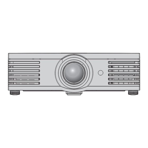
Page 12: Projector
About Your Projector Projector Top and front view Air exhaust port Lens shift dial/Vertical Heated air comes (page 16) out of this opening. Lens shift dial/Horizontal (page 16) Air filter (page 41) MAIN POWER Switch the projector on/off Projection lens (page 20) Lens cover Remote control... - Page 13 About Your Projector Back and bottom view Security lock Attach the commercial shackle lock, manufactured by Air intake port Kensington, to protect your Top cover Hold at the back corner of the Top projector. Compatible with the cover and slightly push up to Kensington MicroSaver Security open.
-
Page 14: Setting Up
Setting up Screen size and throw distance You can adjust the projection size with 2.0 power zoom lens. Calculate and define the throw distance as follows. Screen Projection size (16 : 9) Throw distance (L) Diagonal length Minimum distance Maximum distance Screen height (SH) Screen width (SW) (SD) -
Page 15: Projection Method
Setting up Projection method You can use the projector with any of the following 4 projection methods. To set the desired method in the projector, see “INSTALLATION” on page 39. Setting on a desk/floor and Setting on a desk/floor and projecting from front projecting from rear INSTALLATION: FRONT/DESK... -
Page 16: Lens Shift And Positioning
Setting up Lens shift and positioning If the projector is not positioned right in front of the centre of the screen, you can adjust the projected image position by moving the Lens shift dials within the shift range of the lens. Adjusting the Lens shift dials Horizontal shift You can place the projector where the projector lens is up to 40% horizontally off-centre from the screen and... - Page 17 Setting up Projector location range You can determine where to locate the projector by considering the Lens shift dials possibilities. See “Positioning the image” on page 21 for available placement. After fixing the screen position Placement Vertical centre of screen Centre of lens The adjustable projection range 100%...
-
Page 18: Connections
Connections Before connection to the projector Read and follow the operating and connecting instructions of each peripheral device. The peripheral devices must be turned off. Use cables that match each peripheral device to be connected. Confirm the type of video signals. See “List of compatible signals” on page 45. Audio cables must be connected from each peripheral device directly to the audio reproduction system. -
Page 19: Switching The Projector On/Off
Switching the projector on/off Mains lead Ensure all the input devices are connected and turned off before connecting the Mains lead. Connecting Disconnecting Make sure the is switched off Make sure to use the MAIN POWER Mains lead which is 1. -
Page 20: Switching On The Projector
Switching the projector on/off Switching on the projector Power indicator 1. Switch the MAIN POWER on. 3. Press the POWER button. The power indicator lights up in RED. The power indicator lights up in GREEN after flashing for a while. 2. -
Page 21: Projecting An Image
Projecting an image Selecting the input signal 1. Switch on the connected devices. INPUT Press the button to select the required Press the play button of the required device. input method if needed. See "Switching the input signal" on page 23. The image will be projected on the screen. -
Page 22: Remote Control Operation
Remote control operation Operating range You can operate the projector with the Remote control within the remote range 7 m. Facing to the projector Ensure the Remote control emitter is facing to the Remote control signal receptor on front of the projector and press the required buttons to operate. -
Page 23: Switching The Input Signal
Remote control operation Switching the input signal You can switch the input method manually Connected to COMPONENT by pressing the INPUT button. Press the COMPONENT IN IN terminal equipment’s button several times or press I H to cycle signal through the input methods as follows. The actual projected image will be changed in a Connected to SCART IN while. -
Page 24: Adjusting The Waveform Of The Input Signal
Remote control operation Adjusting the waveform of the input signal Adjusting the waveform You can monitor if the brightness and contrast level of the input signal is in the Make sure to adjust to the 0% line first. Any signal level recommended range by displaying it in the below the recommended range will be forced to 0%. -
Page 25: Adjusting The Focus And Zoom
Remote control operation Adjusting the focus and zoom You can adjust the focus and zoom of the display the LENS control menu. See "LENS projected image. Press the LENS button to CONTROL Menu" on page 37. Switching the picture mode You can switch the preset picture mode NORMAL settings by pressing the PIC. -
Page 26: Setting Your Own Colour Profile
Remote control operation Setting your own colour profile You can adjust a selected colour 3. Select a menu item and the I H to adjust individually and save and retrieve under each item level. the PICTURE MODE setting. Press the The result box is displayed on the right of the COLOR MANAGEMENT button to open cursor and shows the adjusted colour. - Page 27 Remote control operation Loading saved profiles Managing stored logs You can edit or delete the stored logs of the When profiles are loaded under the PICTURE selected PICTURE MODE. MODE setting, you can keep them as you defined 1. Select LOG and press ENTER. until the PROFILE is set to NORMAL.
-
Page 28: Settings
Menu Navigation The menu system allows you to access functions which do not have their own dedicated buttons on the Remote control. The menu options are structured and categorised. You can navigate through the menu with F G I H buttons. -
Page 29: Main Menu And Sub-Menu
Menu Navigation Main menu and Sub-menu The Main menu has 5 options. Select the required menu item and press ENTER to display the Sub-menu. NOTE: Some default settings vary by the selected input signal. PICTURE See “PICTURE Menu” on page 31. Sub-menu items Default setting Sub-menu items... - Page 30 Menu Navigation LANGUAGE Press F G to select the required language and press ENTER. OPTION See “OPTION Menu” on page 38. Sub-menu items Default setting Sub-menu items Default setting INPUT GUIDE DETAILED INSTALLATION FRONT/DESK OSD DESIGN TYPE1 SLEEP OSD POSITION CENTRE ALTITUDE BACK COLOUR...
-
Page 31: Picture Menu
PICTURE Menu COLOUR You can adjust the colour saturation of the projected image. See “Navigating through Lighter Darker the MENU” on page 28. Setting range: -32 to +32 PICTURE MODE When PC is connected, this function is available with 1 125 (1 080)/60i, 1 125 (1 080)/50i, Depending on the projection environment, you can use 1 125 (1 080)/60p and 1 125 (1 080)/50p signals these preset parameter settings to optimise image... -
Page 32: Dynamic Iris
PICTURE Menu DYNAMIC IRIS ADVANCED MENU You can switch automatic adjustment of the lamp and From the ADVANCED MENU, you can perform more the lens iris on/off. detailed image adjustment manually. • ON: Automatic adjustment GAMMA • OFF: No adjustment You can adjust linear intensity at 3 levels. -
Page 33: Memory Save
PICTURE Menu MPEG NR MEMORY SAVE You can switch the automatic noise reduction system for MPEG format images on/off. The You can save the adjusted PICTURE settings with up to system minimises block noise and mosquito noise 5 in each of 2 signal groups. to eliminate jagged edges, providing an overall 1. -
Page 34: Position Menu
POSITION Menu DOT CLOCK If you have interference patterns on the projected image, which is sometimes referred to as moire or noise, you can minimise it by pressing I H to adjust the clock frequency. See “Navigating through the MENU” on page 28. H - POSITION You can move the projected image horizontally for fine adjustment. -
Page 35: Aspect
POSITION Menu ASPECT You can switch the aspect ratio manually when needed. Aspect ratio options and projection example If you apply the aspect ratio options to the projected image, the result will be as follows. The result may differ due to the input signals. See “Switching the aspect ratio” on page 23. VIDEO/S-VIDEO/COMPONENT Not available with 1 125 (1 080)/50i, 1 125 (1 080)/60i, 1 125 (1 080)/50p, 1 125 (1 080)/60p, 1 125 (1 080)/24p, 750 (720)/50p and 750 (720)/60p signals. -
Page 36: Wss
POSITION Menu Aspect ratio depend on signals OVER SCAN Press I H to cycle through the aspect ratio options. The cycle pattern depends on the If the 4 edges of an image is partly dropped, you can use connected signals. this function to adjust and project it properly. -
Page 37: Lens Control Menu
LENS CONTROL Menu ZOOM/FOCUS You can use the 2 different test patterns to adjust the focus and zoom of the image. See “Lens shift and positioning” on page 16. 1. Press ENTER to display test pattern 1. Press F G to adjust the focus and I H to adjust the zoom. RETURN FOCUS ZOOM... -
Page 38: Option Menu
OPTION Menu OSD POSITION You can change the position where to display the menu. Press I H to cycle through the options. UPPER UPPER UPPER See “Navigating through LEFT CENTRE RIGHT the MENU” on page 28. INPUT GUIDE CENTRE When you press INPUT or the INPUT SELECT button to change the input method, the guidance appears in the upper right corner of the screen. -
Page 39: Installation
OPTION Menu INSTALLATION LAMP RUNTIME When installing the projector, select the projection You can check how long the lamp has been used. method according to the projector position. Press I H to cycle through the options. See “Projection method” NOTE: on page 15. -
Page 40: Temp And Lamp Indicators
TEMP and LAMP Indicators Controlling alerts If a problem should occur with the projector, the TEMP and/or LAMP indicators will alert you. Respond to the alert as follows. 1. Confirm the POWER indicator status and turn off the projector in the proper way. 2. -
Page 41: Care And Replacement
Care and Replacement Before cleaning Ensure the projector is switched off. Unplug all the cables from the projector. Cleaning your projector Cleaning the outer surface of the projector Wipe off dirt and dust gently with a soft cloth. If it is difficult to remove the dirt, soak a cloth in a neutral detergent diluted with water, wring the cloth well and then wipe the projector. -
Page 42: Before Replacing The Lamp Unit
Care and Replacement Before replacing the Lamp unit Ensure the projector is switched off. Unplug all the cables from the projector. Prepare a Phillips-head screwdriver. Contact an Authorised Service Centre to purchase a replacement Lamp unit (ET-LAE1000). NOTE: Prior to replacing the lamp unit, allow it to cool down to prevent the risk of burns, damage and other hazards. Do not attempt replacement with an unauthorised lamp unit. -
Page 43: Resetting The Lamp Runtime
Care and Replacement Removing and replacing the lamp unit 1. Use a Phillips screw driver to loosen the 3 lamp unit fixing Lamp unit screws until the screws turn freely. fixing screws 2. Hold the handle of the lamp unit and release the lamp unit lock. -
Page 44: Troubleshooting
Troubleshooting Should any problem persist, contact your dealer. Reference Problem Cause page The mains lead may not be connected. The MAIN POWER switch is turned off. No electric supply is at the mains socket. Power does not turn on. TEMP indicator is lit or flashes. LAMP indicator is lit or flashes. -
Page 45: Technical Information
Technical Information List of compatible signals Scanning Display Dot clock frequency Picture resolution Mode frequency Format quality (MHz) (dots) (kHz) (kHz) NTSC/NTSC 4.43/ 720 x 480i 15.7 59.9 VIDEO/S-VIDEO/SCART PAL-M/PAL60 PAL/PAL-N/SECAM 720 x 576i 15.6 50.0 VIDEO/S-VIDEO/SCART 525i (480i) 720 x 480i 15.7 59.9 13.5... -
Page 46: Serial Terminal
Technical Information Serial terminal The serial connector which is on the connector panel of the projector conforms to the RS-232C interface specification, so that the projector can be controlled by a personal computer which is connected to this connecter. Connection D-sub 9 pin (male) Serial terminal (male) -
Page 47: Control Commands
Technical Information Control commands Command Control contents Remarks In standby mode, all commands other than the PON command are Power ON ignored. The PON command is ignored during lamp ON control. If a PON command is received while the cooling fan is operating after Power OFF the lamp has switched off, the lamp is not turned back on again straight away in order to protect the lamp. -
Page 48: Inquiry Commands
Technical Information Inquiry commands Command Control contents Parameter Power status 000 = OFF 001 = ON FREEZE status 0 = OFF 1 = ON Parameter: (page 23) SVD = S-VIDEO IN VID = VIDEO IN HD1 = HDMI1 IN Input signal status RG1 = PC IN HD2 = HDMI2 IN YUV = COMPONENT IN... -
Page 49: Menu Structure
Technical Information Menu structure PICTURE Menu ....... 31 H NORMAL DYNAMIC PICTURE MODE ....31 H CINEMA1 FULL SCAN(Y) CONTRAST......31 H CINEMA2 FULL SCAN(R) BRIGHTNESS ....... 31 H CINEMA3 FULL SCAN(G) COLOUR ....... 31 H COLOUR1 FULL SCAN(B) TINT........31 H COLOUR2 SINGLE LINE SCAN(Y) SHARPNESS ...... -
Page 50: Specifications
Specifications Power supply AC 100 - 240 V 50 Hz/60 Hz 240 W Power consumption During standby (when fan is stopped): 0.08 W Amps 2.8 A - 1.2 A Panel size (diagonal) 0.74 type (17.78 mm) Aspect ratio 16 : 9 LCD panel Display method 3 transparent LCD panels (RGB) - Page 51 Specifications Single - line, Mini DIN 4p S-VIDEO IN Ω Y: 1.0 V [p-p], C: 0.286 V [p-p], 75 Single - line, RCA pin jack VIDEO IN Ω 1.0 V [p-p], 75 Single - line, D - sub HD 15-pin (female) R.G.B.
-
Page 52: Dimensions
Dimensions Units: mm (inch) 15 (9/16) 230 (9-1/32) 460 (18-3/32) 52 - E NGLISH... -
Page 53: Trademark Acknowledgements
Trademark acknowledgements VGA and XGA are trademarks of International Business Machines Corporation. S-VGA is a registered trademark of the Video Electronics Standards Association. HDMI, the HDMI logo and High-Definition Multimedia Interface are trademarks or registered trademarks of HDMI Licensing LLC. The font used in the on-screen displays is a Ricoh bitmap font, which is manufactured and sold by Ricoh Company, Ltd. -
Page 54: Index
Index ..........9 ..........34 Accessories H- POSITION ........32 ADVANCED MENU HDMI IN ..........18 .............41 Air filter Connection ..........13 ..........39 Terminal ALTITUDE ....... 38 HDMI SIGNAL LEVEL ...........35 ASPECT ..........35 Options ........23 Remote control INPUT .......11 Remote control button ........ - Page 55 Index Navigation buttons SCART IN .........12 ..........18 Control panel button Connection ........11 ..........13 Remote control Terminal ........32 ..........14 NR (Noise Reduction) Screen size SERIAL ........... 48 Basic format ............38 OPTION ......... 48 Cable specifications ..........38 OSD DESIGN ......