Advertisement
Quick Links
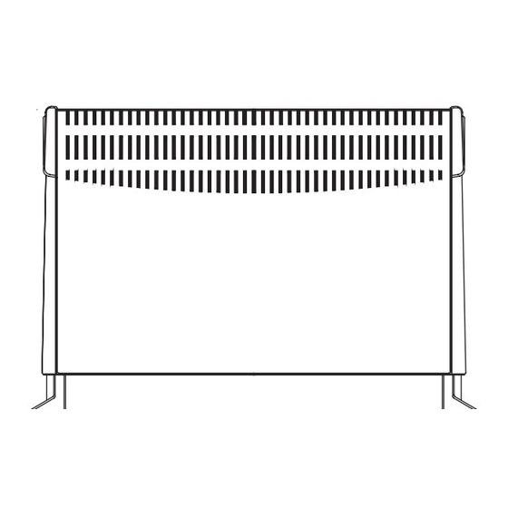
Glen Convector Heaters
Models : 2570, 2571 and 2572
Dimensions
(millimetres)
Models
Specification
2570
2.0kw Heat Switch
2571
2.0kw Thermostat
2572
2.0kw Thermostat, Timer, Mains Neon
IMPORTANT: THESE INSTRUCTIONS SHOULD BE READ CAREFULLY AND RETAINED FOR FUTURE REFERENCE
IMPORTANT SAFETY ADVICE
WARNING –THIS APPLIANCE MUST NOT BE USED IN A
BATHROOM.
WARNING - DO NOT USE THIS HEATER IN THE IMMEDIATE
SURROUNDINGS OF A BATH, A SHOWER OR A SWIMMING POOL.
WARNING – THIS HEATER MUST NOT BE LOCATED
IMMEDIATELY BELOW A FIXED SOCKET OUTLET.
DO NOT USE THE HEATER UNTIL THE FEET OR WALL BRACKETS
ARE FITTED CORRECTLY.
NEVER cover or obstruct in any way the heat outlet slots at
the top of the heater or the air inlet slots in the base of the
heater.
The heater carries a warning 'DO NOT COVER' to alert the
user to the risk of fire that exists if the heater is
accidentally covered.
This appliance is not intended for use by children or other
persons without assistance or supervision if their
physical, sensory or mental capabilities prevent them from
using it safely. Children should be supervised to ensure
that they do not play with the appliance.
If young children, the aged or infirm are likely to be left in
the vicinity of the heater, we advise that adequate
precautions should be taken.-
We recommend that a guard be fitted to ensure contact
with the heater is avoided and objects cannot be inserted
into the product.
Timer model 2572 can be set to switch on automatically,
remember to observe all safety warnings at all times .
If the mains lead is damaged, it must be replaced by the
manufacturer or its service agent or a similarly qualified
person in order to avoid a hazard.
Electrical connection
WARNING – THIS APPLIANCE MUST BE EARTHED
This heater must be used on an AC ~ supply only and the voltage marked
on the heater must correspond to the supply voltage. If fitting a 13 amp
plug, a 13 amp fuse approved by ASTA to BS 1362 must be used. If any
other type of type of plug is used, a 15 amp fuse must be fitted in the
plug, the adaptor, or at the distribution board.
IMPORTANT - The wires in the mains lead are coloured in accordance
with the following code:
GREEN and YELLOW
BLUE
BROWN
Connect the GREEN AND YELLOW wire to the terminal marked 'E' or
by the earth symbol
, or coloured GREEN or GREEN AND YELLOW.
Connect the BROWN wire to the terminal markef 'L' or coloured RED.
Connect the BLUE wire to the terminal marked 'N' or coloured BLACK.
This appliance must only be used on A.C. mains supply of 230-240 Volts~.
-
EARTH
-
NEUTRAL
-
LIVE
Installation and Operating Instructions
230
610
MIN
432
General
The heater may be used free standing on feet or wall mounted on
brackets. The necessary feet, screws and wall brackets are provided.
The heater should only be operated when in the upright position as
shown.
Removal of the wall mounting brackets
Four identical wall mounting brackets are secured to the base of the
heater, using one of the foot fixing screws. These brackets must be
removed before using the heater, as follows : Lay the heater on its back.
Following the sequence in Fig. 2, identify and remove the foot fixing
screw securing the brackets (A). Slide the brackets out (B), then swing
them down to disengage them from the slot in the base of the heater
(C). Withdraw the brackets from the slot (D).
Foot
fixing
screw
A
Free standing use
NEVER USE THE HEATER FREE STANDING WITHOUT THE FEET
FITTED.
Before attempting to secure the feet, ensure that the wall mounting
brackets have been removed from the base of the heater – see
'Removal of the wall mounting brackets'.
Lay the heater on its back, and remove the foot fixing screws at each
end of the heater base, identified as shown in Fig. 3.
The feet are marked 'LH' and RH' and must be fitted correctly, when
looking at the base of the heater. Offer each foot up to the heater base
so that the holes in the foot align with the fixing holes, identified by
arrows, as shown in Fig. 3.
Using an X–head screwdriver, insert and tighten the fixing screws to
secure the foot.
Foot
fixing
screws
LH
foot
INGCUK7012
shelf/ceiling
300
MIN
230
165
MIN
360
230
MIN
Floor Mtd.
Wall Mtd.
B
C
Issue 5
Fig. 1
D
Fig. 2
Foot
fixing
holes
Fig. 3
Advertisement

Related Manuals for Glen 2570


Summary of Contents for Glen 2570
- Page 1 Installation and Operating Instructions Glen Convector Heaters INGCUK7012 Issue 5 Models : 2570, 2571 and 2572 Dimensions shelf/ceiling (millimetres) Models Specification 2570 2.0kw Heat Switch 2571 2.0kw Thermostat 2572 2.0kw Thermostat, Timer, Mains Neon Floor Mtd. Wall Mtd. Fig. 1...
-
Page 2: Using The Heater
The heat outlet grille may become discoloured with use – this is caused by airborne pollution and is not a fault. Moving the heater Heat Selection switch (2570 model only) DO NOT move the heater when it is ON. The heat selection switch is an economy feature. - Page 3 Timer Model (2572 model only) REMEMBER TO OBSERVE ALL SAFETY WARNINGS AT ALL TIMES Manual Operation – Slide the control switch to : - (see Fig. 6). - The heater is OFF, but the timer clock continues to keep time whilst the heater is connected to the mains supply and the power Fig.
- Page 4 Hampshire. SO30 2DF Republic of Ireland Tel. 01 8424833 [c] Glen Dimplex UK Limited All rights reserved. Material contained in this publication may not be reproduced in whole or in part, without prior permission in writing of Glen Dimplex UK Limited.
Need help?
Do you have a question about the 2570 and is the answer not in the manual?
Questions and answers