Sharp XR-10X-L Service Manual
Hide thumbs
Also See for XR-10X-L:
- Operation manual (71 pages) ,
- Specifications (2 pages) ,
- Specification (2 pages)
Table of Contents
Advertisement
TopPage
Important Service Safety Notes .............i
Precautions For Using Lead-Free Solder ... . ..........vi
[1]
Specifications ......................................... . ....... 1-1
[2]
Parts Name And Basic Operation........... . ....... 1-2
[3]
Dimensions ........................................ . ....... 1-8
[4]
Regarding The Lamp................................ . ....... 1-9
[1]
[2]
Removing The Top Body .......................... . ....... 2-1
[3]
Removing The Main Pwb Unit ................ . ....... 2-2
[4]
Removing the speaker, fan, and power
supply ballast unit................................... . ....... 2-2
[5]
Removing the optical mechanism unit and
RC light receiver PWB ........................... . ....... 2-3
[6]
Removing the photosensor PWB unit,
blower fan, DMD PWB, and DMD .......... . ....... 2-3
[1]
The Optical Unit Outline.............. . ....... 3-1
CHAPTER 4. ELECTRICAL ADJUSTMENT
[1]
ELECTRICAL ADJUSTMENT................ . ....... 4-1
[2]
Adjustment Mode Process Menu............ . ....... 4-4
Parts marked with "
" are important for maintaining the safety of the set. Be sure to replace these parts with specified ones for maintaining the
safety and performance of the set.
XR-10X-L/XR-10S-L/XG-MB50X-L/XR-11XC-L/XR-HB007X-L
SERVICE MANUAL
MULTIMEDIA PROJECTOR
XR-HB007X-L
MODELS
CONTENTS
[1]
Trouble Shooting Table .....................5-1
CHAPTER 6. BLOCK DIAGRAM/OVERALL WIRING
DIAGRAM
[1]
BLOCK DIAGRAM.........................................6-1
[2]
Overall Wiring Diagram ......................6-3
CHAPTER 7. PRINTED WIRING BOARD
[1]
Main Unit ......................................................7-1
[2]
Dmd Unit .......................................................7-9
........ 2-1
[3]
Ballast Power Unit............................... 7-11
[4]
Ballast Control Unit...........................7-17
[5]
Photosensor Unit .................................7-19
[6]
R/C Unit .......................................................7-20
[1]
WAVEFORMS ...............................................8-1
[1]
GRAM............................................................9-1
[2]
Schematic Diagram ................................9-2
No. S06X4XR10XLSL
XR-10X-L
XR-10S-L
XR-11XC-L
XG-MB50X-L
This document has been published to be used for
after sales service only.
The contents are subject to change without notice.
Advertisement
Table of Contents

Related Manuals for Sharp XR-10X-L


Summary of Contents for Sharp XR-10X-L
-
Page 1: Service Manual
TopPage XR-10X-L/XR-10S-L/XG-MB50X-L/XR-11XC-L/XR-HB007X-L SERVICE MANUAL No. S06X4XR10XLSL MULTIMEDIA PROJECTOR XR-10X-L XR-10S-L XR-11XC-L XR-HB007X-L XG-MB50X-L MODELS CONTENTS SAFETY PRECAUTION CHAPTER 5. TROUBLE SHOOTING TABLE IMPORTANT SERVICE SAFETY NOTES .....i TROUBLE SHOOTING TABLE .....5-1 Precautions for using lead-free solder ....vi CHAPTER 6. BLOCK DIAGRAM/OVERALL WIRING CHAPTER 1. -
Page 2: Safety Precaution
XR-10X-L/XR-10S-L/XG-MB50X-L/XR-11XC-L/XR-HB007X-L XR-10X-L SAFETY PRECAUTION Service Manual IMPORTANT SERVICE SAFETY NOTES IMPORTANT SERVICE SAFETY NOTES (for USA) Service work should be performed only by qualified service technicians who are thoroughly familiar with all safety checks and servicing guidelines as follows: WARNING Use an AC voltmeter with sensitivity of 5000 ohm per volt., or higher, sensitivity to measure the AC voltage... - Page 3 XR-10X-L/XR-10S-L/XG-MB50X-L/XR-11XC-L/XR-HB007X-L PRECAUTIONS A PRENDRE LORS DE LA REPARATION Ne peut effectuer la réparation qu' un technicien spécialisé qui s'est parfaitement accoutumé à toute vérification de sécurité et aux conseils suivants. AVERTISSEMENT Utiliser un voltmètre CA d'une sensibilité d'au moins 1. N'entreprendre aucune modification de tout circuit.
-
Page 4: Note To Service Personnel
XR-10X-L/XR-10S-L/XG-MB50X-L/XR-11XC-L/XR-HB007X-L NOTE TO SERVICE NOTE POUR LE PERSONNEL PERSONNEL D’ENTRETIEN ////////////////////////////////////////////////////////////// ////////////////////////////////////////////////////////////// UV-RADIATION PRECAUTION PRECAUTION POUR LES RADIATIONS UV ////////////////////////////////////////////////////////////// ////////////////////////////////////////////////////////////// La source de lumière, la lampe, dans le projecteur émet The light source, lamp, in the projector emits small de petites quantités de radiation UV. -
Page 5: Lamp Replacement
XR-10X-L/XR-10S-L/XG-MB50X-L/XR-11XC-L/XR-HB007X-L //////////////////////////////////////////////////////////////// //////////////////////////////////////////////////////////////// UV-RADIATION PRECAUTION (Continued) PRECAUTION POUR LES RADIA TIONS UV (Suite) //////////////////////////////////////////////////////////////// //////////////////////////////////////////////////////////////// Lamp Replacement Remplacement de la lampe Note: Remarque: Since the lamp reaches a very high temperature during Comme la lampe devient très chaude pendant le units operation replacement of the lamp should be fonctionnement de l’unité, son remplacement ne doit... -
Page 6: Power Unit
XR-10X-L/XR-10S-L/XG-MB50X-L/XR-11XC-L/XR-HB007X-L WARNING: High brightness light source, do not stare into the beam of light, or view directly. Be especially careful that children do not stare directly into the beam of light. WARNING: TO REDUCE THE RISK OF FIRE OR ELECTRIC SHOCK, DO NOT EXPOSE THIS UNIT TO MOISTURE OR WET LOCATIONS. - Page 7 XR-10X-L/XR-10S-L/XG-MB50X-L/XR-11XC-L/XR-HB007X-L Precautions for using lead-free solder Employing lead-free solder • "PWBs" of this model employs lead-free solder. The LF symbol indicates lead-free solder, and is attached on the PWBs and service manuals. The alphabetical character following LF shows the type of lead-free solder.
-
Page 8: Specifications
Remote control, Power cord, RGB cable, 3 RCA to 15-pin D-sub cable, DIN-D- sub RS-232C adaptor, Operation manual, Dust filter As a part of policy of continuous improvement, SHARP reserves the right to make design and specification changes for product improvement without prior notice. The performance specifica- tion figures indicated are nominal values of production units. -
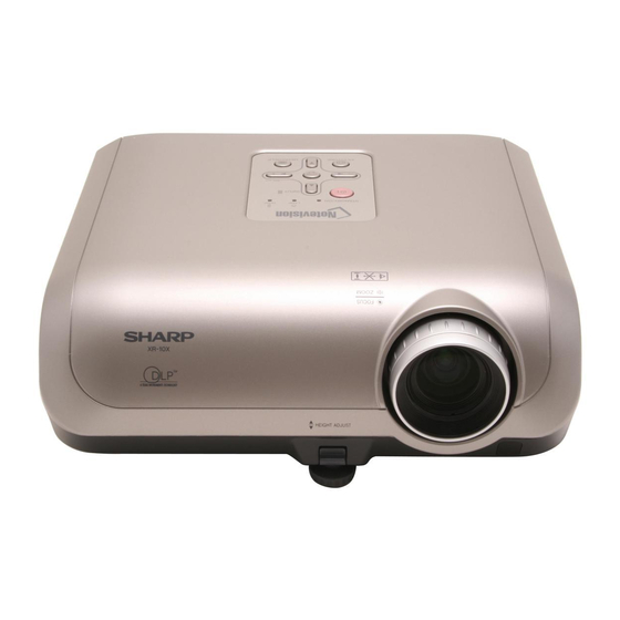
Page 9: Parts Name And Basic Operation
XR-10X-L/XR-10S-L/XG-MB50X-L/XR-11XC-L/XR-HB007X-L [2] Parts Name and Basic Operation Part Names and Functions Projector Top View Power Lamp indicator indicator Temperature warning indicator STANDBY/ON button For turning the power on and Volume buttons putting the / +) projector into For adjusting the speaker standby mode. -
Page 10: Rear View
XR-10X-L/XR-10S-L/XG-MB50X-L/XR-11XC-L/XR-HB007X-L Rear View Terminals Refer to "INPUT Terminals and Connectable Main Equipment". OUTPUT (INPUT 1, 2) AUDIO (INPUT 1, 2) terminal terminal (Shared for (Shared computer RGB and INPUT 1 and 2) component signals output terminal for INPUT 1 and 2) Terminal for connecting a monitor. - Page 11 XR-10X-L/XR-10S-L/XG-MB50X-L/XR-11XC-L/XR-HB007X-L STANDBY button ON button For putting the For turning the power on. projector into the standby mode. MENU/HELP button For displaying adjustment KEYSTONE button and setting screens, and For entering the help screen. Keystone Correction mode. RETURN button Adjustment buttons...
-
Page 12: Inserting The Batteries
XR-10X-L/XR-10S-L/XG-MB50X-L/XR-11XC-L/XR-HB007X-L Inserting the Batteries Press the mark on the cover and slide it in the direction of the arrow. Insert the batteries. Insert the batteries making sure the polarities correctly match marks inside the battery compartment. Attach the cover and slide it until it clicks into place. -
Page 13: Input Terminals And Connectable Main Equipment
XR-10X-L/XR-10S-L/XG-MB50X-L/XR-11XC-L/XR-HB007X-L Connections INPUT Terminals and Connectable Main Equipment COMPUTER-RGB/COMPONENT INPUT 1, 2 terminal OUTPUT terminal ı Connecting the computer. Connecting the monitor when you want ı Connecting video equipment with compo- to simultaneously watch the projection nent output terminal (DVD player, DTV image on the monitor. -
Page 14: Connecting Pin Assignments
XR-10X-L/XR-10S-L/XG-MB50X-L/XR-11XC-L/XR-HB007X-L Connecting Pin Assignments COMPUTER-RGB/COMPONENT INPUT1, 2 and COMPUTER-RGB/COMPONENT OUTPUT Terminals: 15-pin mini D-sub female connector COMPUTER-RGB Input/Output Component Input/Output Video input (red) PR (CR) Video input (green/sync on green) Video input (blue) PB (CB) Not connected Not connected Not connected... -
Page 15: Dimensions
XR-10X-L/XR-10S-L/XG-MB50X-L/XR-11XC-L/XR-HB007X-L [3] DIMENSIONS Units: inches (mm) φ9 (69.2) (80) (77.5) (315) (33.8) (46.2) (65.5) (75) 1 – 8... -
Page 16: Regarding The Lamp
Sharp Authorized Projector Dealer or Service Center. * If the new lamp does not light after replacement, take your projector to the nearest Sharp Authorized Projector Dealer or Service Center for repair. -
Page 17: Removing And Installing The Lamp Unit
XR-10X-L/XR-10S-L/XG-MB50X-L/XR-11XC-L/XR-HB007X-L Removing and Installing the Lamp Unit Lamp unit AN-XR10L2 Warning! (for XG-MB50X-L/ Optional XR-11XC-L/XR-10X-L/ Do not remove the lamp unit from the projec- XR-10S-L/ accessory tor right after use. The lamp and parts around XR-HB007X-L) the lamp will be very hot and may cause burns or injury. -
Page 18: Resetting The Lamp Timer
XR-10X-L/XR-10S-L/XG-MB50X-L/XR-11XC-L/XR-HB007X-L Regarding the Lamp (Continued) Remove the lamp unit. Handle Loosen the securing screws from the lamp unit. Hold the lamp unit by the handle and pull it in the direction of the arrow. At this time, keep the lamp unit horizontal and do not tilt it. - Page 19 XR-10X-L/XR-10S-L/XG-MB50X-L/XR-11XC-L/XR-HB007X-L CHAPTER 2. XR-10X-L REMOVING OF MAJOR PARTS Service Manual [1] Removing the lamp door and the lamp unit 1. Loosen the lamp door fixing screw. Lift off the lamp door. 2. Remove 2 lamp unit fixing screws to detach the lamp unit.
-
Page 20: Removing The Main Pwb Unit
XR-10X-L/XR-10S-L/XG-MB50X-L/XR-11XC-L/XR-HB007X-L [3] Removing the main PWB unit 1. Remove all connectors from the main PWB unit. 2. Remove 2 terminal fixing screws. 3. Remove 3 main PWB fixing screws to detach the main PWB unit. [CW] [RC] [FA] [MO] [LF]... -
Page 21: Rc Light Receiver Pwb
XR-10X-L/XR-10S-L/XG-MB50X-L/XR-11XC-L/XR-HB007X-L [5] Removing the optical mechanism unit and RC light receiver PWB 1. Remove 4 optical mechanism unit fixing screws to detach the optical mechanism unit. 2. Remove the RC light receiver PWB unit. Optical Mechanism Unit RC Light Receiver PWB [6] Removing the photosensor PWB unit, blower fan, DMD PWB, and DMD 1. -
Page 22: Schematic Diagram
XR-10X-L/XR-10S-L/XG-MB50X-L/XR-11XC-L/XR-HB007X-L CHAPTER 3. XR-10X-L THE OPTICAL UNIT OUTLINE Service Manual [1] THE OPTICAL UNIT OUTLINE 1. Layout for proper setup of the optical components and parts (top view) (Schematic diagram) Projection lens Illumination lens 2 Illumination lens 1 Reflection mirror... - Page 23 XR-10X-L/XR-10S-L/XG-MB50X-L/XR-11XC-L/XR-HB007X-L 2. When the DMD unit has been replaced If shading shown in Figure 1 appears on the screen after replacing DMD, turn the adjustment screw of the optical engine to adjust the lighting area of DMD. 1. Loosen the adjustment lever fixing screw .
-
Page 24: Chapter 4. Electrical Adjustment 1] Electrical Adjustment
XR-10X-L/XR-10S-L/XG-MB50X-L/XR-11XC-L/XR-HB007X-L CHAPTER 4. XR-10X-L ELECTRICAL ADJUSTMENT Service Manual [1] ELECTRICAL ADJUSTMENT Adjusting point Adjusting conditions Adjusting procedure •Make the following settings. EEPROM 1. Turn on the power (with the lamp on) and initialization warm up the set for 15 minutes. - Page 25 XR-10X-L/XR-10S-L/XG-MB50X-L/XR-11XC-L/XR-HB007X-L Adjusting point Adjusting conditions Adjusting procedure Adjustment of Component offset 1. Feed 10-step signal with 480P component 1. Check the fixed value. 100% amplitude. C-R-OS : 260 2. Select the following group and subjects. C-B-OS : 260 Group : CONFIRM/AD...
- Page 26 XR-10X-L/XR-10S-L/XG-MB50X-L/XR-11XC-L/XR-HB007X-L Adjusting point Adjusting conditions Adjusting procedure Delivery settings 1. Make the following settings. Destination Process Remote control adjustment adjustment Factory setting at 4 China Factory setting at 6 Others Factory setting at 3 * Writing a software program (before main PWB is mounted) Use the DLP Composer Lite Ver.
-
Page 27: Adjustment Mode Process Menu
XR-10X-L/XR-10S-L/XG-MB50X-L/XR-11XC-L/XR-HB007X-L Adjustment mode process menu 1st Layer 2nd Layer Default ADJUST CW/Auto KS CW-INDEX K-SENS AD/DLP R-CONT G-CONT B-CONT R-GAIN G-GAIN B-GAIN — — — — — — CONFIRM R-BRIGHT G-BRIGHT B-BRIGHT C-R-OS C-B-OS R-BLK G-BLK B-BLK S-R-OS S-G-OS S-B-OS... - Page 28 XR-10X-L/XR-10S-L/XG-MB50X-L/XR-11XC-L/XR-HB007X-L 1. Adjustment of ballast unit output power (lamp power) 1. List of parts requiring adjustment When replacing the following parts, adjust the ballast unit output power (lamp power). Part name Ref No. Part code Cement resistor R905 RR-FZA002WJZZ Ballast Control PWB ——...
- Page 29 XR-10X-L/XR-10S-L/XG-MB50X-L/XR-11XC-L/XR-HB007X-L CHAPTER 5. XR-10X-L TROUBLE SHOOTING TABLE Service Manual [1] TROUBLE SHOOTING TABLE Checking the basic operation Has P1701 come off or is it Does the power LED light Fully insert the connector. loose? up or flash in red or green?
- Page 30 XR-10X-L/XR-10S-L/XG-MB50X-L/XR-11XC-L/XR-HB007X-L 5 – 2...
- Page 31 XR-10X-L/XR-10S-L/XG-MB50X-L/XR-11XC-L/XR-HB007X-L DMD system check Check P2501 for breakage and solder crack and peripheral resistance for solder crack. Check SC9101 for breakage and solder crack. Is there any vertical stripe (block noise) on the Screen? Is the screen all black? The main PWB and DMD PWB are in poor contact.
- Page 32 XR-10X-L/XR-10S-L/XG-MB50X-L/XR-11XC-L/XR-HB007X-L Power supply PWB check Is 6 V applied to pins (7) and (8) of the connector P704? Is 13 V applied to pins (3) Check peripheral circuits of and (4) of the connector IC703. P704? Does the lamp turn on? Check the main PWB.
- Page 33 XR-10X-L/XR-10S-L/XG-MB50X-L/XR-11XC-L/XR-HB007X-L Are connectorsP701 and Securely insert the connectors. P702 fully inserted? Is AC voltage between 100 Replace F701. 240 V applied to both ends of C707? Press the red button on the Is the bimetal broken? bimetal. (Connection between 1 and...
- Page 34 XR-10X-L/XR-10S-L/XG-MB50X-L/XR-11XC-L/XR-HB007X-L Checking the lamp light-up Go to "Check when the Does the lamp turn on lamp turns off soon after when the power is turned turning on". Securely insert the Is the lamp tight in the connectors. socket? Has the FPC cable to...
- Page 35 XR-10X-L/XR-10S-L/XG-MB50X-L/XR-11XC-L/XR-HB007X-L Check when the lamp turns off soon after turning on Have connectors P1703, Securely insert the P1721, P1722, P1723 and P1724 come off or are they connectors. loose? Is each cooling fan Check the cooling fan. rotating? Check peripheral circuits of Is approx.
- Page 36 XR-10X-L/XR-10S-L/XG-MB50X-L/XR-11XC-L/XR-HB007X-L RGB and component signal check Send component signal or RGB signal of 1080i (or 720P) from INPUT 1 or INPUT 2. Select INPUT 1 or INPUT 2 using keys on the main unit or the remote control. Is image displayed...
- Page 37 XR-10X-L/XR-10S-L/XG-MB50X-L/XR-11XC-L/XR-HB007X-L S-VIDEO (INPUT 3) VIDEO (INPUT 4) check check Send S-Video signal (color Send VIDEO signal from signal) from INPUT 3. INPUT 4. Use buttons on Select INPUT 3 using keys the main unit or the remote on the main unit or the control to select INPUT 4.
-
Page 38: Overall Wiring Diagram
XR-10X-L/XR-10S-L/XG-MB50X-L/XR-11XC-L/XR-HB007X-L CHAPTER 6. XR-10X-L BLOCK DIAGRAM/OVERALL WIRING DIAGRAM Service Manual [1] BLOCK DIAGRAM BLOCK DIAGRAM T903 Q904 6 – 1... - Page 39 XR-10X-L/XR-10S-L/XG-MB50X-L/XR-11XC-L/XR-HB007X-L TH9102 6 – 2...
- Page 40 XR-10X-L/XR-10S-L/XG-MB50X-L/XR-11XC-L/XR-HB007X-L [2] OVERALL WIRING DIAGRAM OVERALL WIRING DIAGRAM 6 – 3...
- Page 41 XR-10X-L/XR-10S-L/XG-MB50X-L/XR-11XC-L/XR-HB007X-L 6 – 4...
-
Page 42: Chapter 7. Printed Wiring Board 1] Main Unit
XR-10X-L/XR-10S-L/XG-MB50X-L/XR-11XC-L/XR-HB007X-L CHAPTER 7. XR-10X-L PRINTED WIRING BOARD Service Manual [1] MAIN Unit MAIN Unit (Side-A) C 1726 P 2533 F B 1708 F B 1709 R 2019 IC 2001 +2.5V S C 2531 C 2028 R 2504 VTE R M1.8V... - Page 43 XR-10X-L/XR-10S-L/XG-MB50X-L/XR-11XC-L/XR-HB007X-L P 1702 P 1721 S C 3581 P 1705 P 3562 F B 1729 R 1707 L1723 L1727 C 1724 R 1797 R 1798 C 3588 C 3591 C 3586 D1725 Q1724 C 1726 QPWBXE 004WJZZ DUNTKE 004WE P 1723...
- Page 44 XR-10X-L/XR-10S-L/XG-MB50X-L/XR-11XC-L/XR-HB007X-L MAIN Unit (Chip Parts Side-A) P1703 R 1704 R 170 P2533 R 2528 R 2529 R 2507 R 2509 R 2511 R 2513 R 2515 R 2517 R 2522 C2002 FB1708 IC2001 FB1709 C2028 R 2001 C2003 R 2506...
- Page 45 XR-10X-L/XR-10S-L/XG-MB50X-L/XR-11XC-L/XR-HB007X-L P3562 P1702 P1703 P1721 S C3581 P1705 FB3584 FB3585 R 1704 R 1706 L1723 L1727 R 1707 FB1729 C1724 FB1728 C3591 C3586 C3588 R 1797 R 1798 D1725 FB1727 Q1724 P2533 R 1762 C1718 R 1728 FB1732 FB1731 D1726...
- Page 46 XR-10X-L/XR-10S-L/XG-MB50X-L/XR-11XC-L/XR-HB007X-L MAIN Unit (Side-B) R 3578 C 3571 LUG 3103 D1702 TH3561 R 3577 L1721 Q1721 C 1704 C 1728 C 3593 D1723 Q1722 R 3597 IC 1762 C 1761 R 1764 C 1763 R 3596 R 3595 C 2231...
- Page 47 XR-10X-L/XR-10S-L/XG-MB50X-L/XR-11XC-L/XR-HB007X-L LUG 2501 F B 2251 C 2231 R 2017 D2231 LUG 3104 X2251 R 2232 R 2520 R 2013 R 2502 R 2519 L2005 C 2247 IC 2251 R 2248 R 2231 R 2242 L2004 R 2243 R 2531...
- Page 48 XR-10X-L/XR-10S-L/XG-MB50X-L/XR-11XC-L/XR-HB007X-L MAIN Unit (Chip Parts Side-B) R 3578 C3571 TH3561 R 3577 D1702 C1704 C3594 D1723 D3584 R 1725 D3581 D3582 D3583 C3592 Q1722 C1728 R 1722 R 1723 R 3597 C3595 C3583 C1771 R 1724 R 1721 R 3596...
- Page 49 XR-10X-L/XR-10S-L/XG-MB50X-L/XR-11XC-L/XR-HB007X-L P2501 1722 FB2251 C1768 C2254 C2231 D2231 X2251 C2232 R 2520 R 2232 C2233 IC2231 R 2234 R 2235 R 2231 R 2519 L2005 R 2242 C2247 R 2243 R 2248 R 2245 R 2009 R 2247 R 2246...
-
Page 50: Dmd Unit
XR-10X-L/XR-10S-L/XG-MB50X-L/XR-11XC-L/XR-HB007X-L [2] DMD Unit DMD Unit (Side-A) TH9102 C9102 C9101 R9103 C9507 C9313 FB9302 C9505 C9310 C9511 C9307 C9501 DMD Unit (Chip Parts Side-A) 7 – 9... - Page 51 XR-10X-L/XR-10S-L/XG-MB50X-L/XR-11XC-L/XR-HB007X-L DMD Unit (Side-B) 7 – 10...
-
Page 52: Ballast Power Unit
XR-10X-L/XR-10S-L/XG-MB50X-L/XR-11XC-L/XR-HB007X-L [3] BALLAST POWER Unit BALLASUT POWER Unit (Side-A) R 765 R 746 C 728 C 737 D714 IC 703 C 725 D715 C 727 R 741 C 731 C 730 C 738 C OLD D711 C 721 D716 D709... - Page 53 XR-10X-L/XR-10S-L/XG-MB50X-L/XR-11XC-L/XR-HB007X-L R 713 C 735 C 714 6.3A-250V P 701 L705 R 701 C 707 L702 R 727 C 740 V A701 R 724 R 720 R 719 R 722 F 705 D703 Q704 Q702 D701 F B 707 C 709...
- Page 54 XR-10X-L/XR-10S-L/XG-MB50X-L/XR-11XC-L/XR-HB007X-L BALLASUT POWER Unit (Side-B) R 713 C 714 C 735 R 762 C 703 R 711 C 713 C 705 R 704 R 703 R 705 D705 C 702 C 706 R 702 R 718 R 701 R 732...
- Page 55 XR-10X-L/XR-10S-L/XG-MB50X-L/XR-11XC-L/XR-HB007X-L R 765 F B 701 F B 702 R 708 R 707 R 746 R 759 R 760 R 706 D714 C 728 IC 703 R 736 C 737 R 758 R 757 R 735 R 752 R 754...
- Page 56 XR-10X-L/XR-10S-L/XG-MB50X-L/XR-11XC-L/XR-HB007X-L BALLAST POWER Unit (Chip Parts Side-B) R 762 R 708 R 711 C703 R 707 C713 C705 C706 R 710 R 703 R 704 R 705 R 706 C702 D705 R 702 R 718 D704 R 732 C708 R 728...
- Page 57 XR-10X-L/XR-10S-L/XG-MB50X-L/XR-11XC-L/XR-HB007X-L FB701 R 708 FB702 R 707 R 706 R 759 R 760 R 758 R 757 R 736 C724 R 735 R 752 R 754 R 756 C723 R 743 R 753 C736 R 751 R 755 D710 R 738...
-
Page 58: Ballast Control Unit
XR-10X-L/XR-10S-L/XG-MB50X-L/XR-11XC-L/XR-HB007X-L [4] BALLAST CONTROL Unit BALLAST CONTROL Unit (Side A) R7704 P7701 C7701 D7715 R7708 R7761 C7745 D7714 IC7707 C7709 C7727 R7719 R7775 R7776 D7713 C7742 C7712 C7713 C7728 R7726 C7710 R7793 R7721 D7711 C7715 IC7709 C7719 C7734 R7731 D7703... - Page 59 XR-10X-L/XR-10S-L/XG-MB50X-L/XR-11XC-L/XR-HB007X-L BALLAST CONTROL Unit (Side B) R7702 R7703 C7735 IC7704 R7705 C7702 R7739 Q7702 R7710 C7706 Q7701 C7705 C7708 C7703 R7748 R7781 C7704 R7788 Q7711 R7728 R7713 R7756 R7718 R7711 IC7705 R7786 R7785 R7701 C7711 R7716 R7753 R7735 C7723 R7730...
-
Page 60: Photosensor Unit
XR-10X-L/XR-10S-L/XG-MB50X-L/XR-11XC-L/XR-HB007X-L [5] PHOTOSENSOR Unit PHOTOSENSOR Unit (Side-A) PHOTOSENSOR Unit (Side B) R1109 R1108 R1106 R1107 PHOTOSENSOR Unit (Chip Parts Side B) 7 – 19... -
Page 61: R/C Unit
XR-10X-L/XR-10S-L/XG-MB50X-L/XR-11XC-L/XR-HB007X-L [6] R/C Unit R/C RECEIVER Unit (Side-A) R/C RECEIVER Unit (Side B) 7 – 20... - Page 62 XR-10X-L/XR-10S-L/XG-MB50X-L/XR-11XC-L/XR-HB007X-L CHAPTER 8. XR-10X-L WAVEFORMS Service Manual [1] WAVEFORMS 8 – 1...
-
Page 63: Safety Notes
XR-10X-L/XR-10S-L/XG-MB50X-L/XR-11XC-L/XR-HB007X-L CHAPTER 9. XR-10X-L SCHEMATIC DIAGRAM Service Manual [1] DESCRIPTION OF SCHEMATIC DIA- GRAM 1. VOLTAGE MEASUREMENT CONDITION: 1. Voltages at test points are measured at the supply voltage of AC 100V/CROSS 10V-240. Signals are fed by a color bar signal gener- ator for servicing purpose and the above voltages are measured with a 20k ohm/V tester. - Page 64 XR-10X-L/XR-10S-L/XG-MB50X-L/XR-11XC-L/XR-HB007X-L [2] SCHEMATIC DIAGRAM MAIN Unit-1 9 – 2...
- Page 65 XR-10X-L/XR-10S-L/XG-MB50X-L/XR-11XC-L/XR-HB007X-L 9 – 3...
- Page 66 XR-10X-L/XR-10S-L/XG-MB50X-L/XR-11XC-L/XR-HB007X-L MAIN Unit-2 9 – 4...
- Page 67 XR-10X-L/XR-10S-L/XG-MB50X-L/XR-11XC-L/XR-HB007X-L 9 – 5...
- Page 68 XR-10X-L/XR-10S-L/XG-MB50X-L/XR-11XC-L/XR-HB007X-L MAIN Unit-3 9 – 6...
- Page 69 XR-10X-L/XR-10S-L/XG-MB50X-L/XR-11XC-L/XR-HB007X-L 9 – 7...
- Page 70 XR-10X-L/XR-10S-L/XG-MB50X-L/XR-11XC-L/XR-HB007X-L MAIN Unit-4 9 – 8...
- Page 71 XR-10X-L/XR-10S-L/XG-MB50X-L/XR-11XC-L/XR-HB007X-L 9 – 9...
- Page 72 XR-10X-L/XR-10S-L/XG-MB50X-L/XR-11XC-L/XR-HB007X-L MAIN Unit-5 9 – 10...
- Page 73 XR-10X-L/XR-10S-L/XG-MB50X-L/XR-11XC-L/XR-HB007X-L 9 – 11...
- Page 74 XR-10X-L/XR-10S-L/XG-MB50X-L/XR-11XC-L/XR-HB007X-L MAIN Unit-6 (XR-10X-L/11XC-L/HB007X-L/XG-MB50X-L) 9 – 12...
- Page 75 XR-10X-L/XR-10S-L/XG-MB50X-L/XR-11XC-L/XR-HB007X-L 9 – 13...
- Page 76 XR-10X-L/XR-10S-L/XG-MB50X-L/XR-11XC-L/XR-HB007X-L MAIN Unit-6 (XR-10S-L) 9 – 14...
- Page 77 XR-10X-L/XR-10S-L/XG-MB50X-L/XR-11XC-L/XR-HB007X-L 9 – 15...
- Page 78 XR-10X-L/XR-10S-L/XG-MB50X-L/XR-11XC-L/XR-HB007X-L MAIN Unit-7 9 – 16...
- Page 79 XR-10X-L/XR-10S-L/XG-MB50X-L/XR-11XC-L/XR-HB007X-L 9 – 17...
- Page 80 XR-10X-L/XR-10S-L/XG-MB50X-L/XR-11XC-L/XR-HB007X-L MAIN Unit-8 9 – 18...
- Page 81 XR-10X-L/XR-10S-L/XG-MB50X-L/XR-11XC-L/XR-HB007X-L 9 – 19...
- Page 82 XR-10X-L/XR-10S-L/XG-MB50X-L/XR-11XC-L/XR-HB007X-L DMD Unit-1 DMD Unit-1 9 – 20...
- Page 83 XR-10X-L/XR-10S-L/XG-MB50X-L/XR-11XC-L/XR-HB007X-L 9 – 21...
- Page 84 XR-10X-L/XR-10S-L/XG-MB50X-L/XR-11XC-L/XR-HB007X-L DMD Unit-2 9 – 22...
- Page 85 XR-10X-L/XR-10S-L/XG-MB50X-L/XR-11XC-L/XR-HB007X-L 9 – 23...
- Page 86 XR-10X-L/XR-10S-L/XG-MB50X-L/XR-11XC-L/XR-HB007X-L DMD Unit-3 9 – 24...
- Page 87 XR-10X-L/XR-10S-L/XG-MB50X-L/XR-11XC-L/XR-HB007X-L 9 – 25...
- Page 88 XR-10X-L/XR-10S-L/XG-MB50X-L/XR-11XC-L/XR-HB007X-L BALLAST POWER Unit 9 – 26...
- Page 89 XR-10X-L/XR-10S-L/XG-MB50X-L/XR-11XC-L/XR-HB007X-L AND SHADED COMPONENTS=SAFETY RELATED PARTS 9 – 27...
- Page 90 XR-10X-L/XR-10S-L/XG-MB50X-L/XR-11XC-L/XR-HB007X-L BALLAST CONTROL Unit 9 – 28...
- Page 91 XR-10X-L/XR-10S-L/XG-MB50X-L/XR-11XC-L/XR-HB007X-L AND SHADED COMPONENTS=SAFETY RELATED PARTS 4 5 8 9 – 29...
- Page 92 XR-10X-L/XR-10S-L/XG-MB50X-L/XR-11XC-L/XR-HB007X-L PHOTO SENSOR Unit 9 – 30...
- Page 93 XR-10X-L/XR-10S-L/XG-MB50X-L/XR-11XC-L/XR-HB007X-L 9 – 31...
- Page 94 XR-10X-L/XR-10S-L/XG-MB50X-L/XR-11XC-L/XR-HB007X-L R/C RECEIVER Unit 9 – 32...
- Page 95 XR-10X-L/XR-10S-L/XG-MB50X-L/XR-11XC-L/XR-HB007X-L 9 – 33...
- Page 96 XR-10X-L/XR-10S-L/XG-MB50X-L/XR-11XC-L/XR-HB007X-L — MEMO — 9 – 34...
- Page 97 XR-10X-L/XR-10S-L/XG-MB50X-L/XR-11XC-L/XR-HB007X-L PartsGuide PARTS GUIDE MULTIMEDIA PROJECTOR XR-10X-L XR-10S-L XR-11XC-L XR-HB007X-L XG-MB50X-L MODELS CONTENTS PRINTED WIRING BOARD DUNTKD164WEF4 ASSEMBLIES (R/C RECEIVER Unit) DUNTKE004FMF0/1 (MAIN Unit) CABINET AND MECHANICAL PARTS DUNTKD140WEF0 (DMD Unit) OPTICAL MECHANISM PARTS DUNTKD141WEF4 (PHOTO SENSOR Unit) [10] SUPPLIED ACCESSORIES...
- Page 98 XR-10X-L/XR-10S-L/XG-MB50X-L/XR-11XC-L/XR-HB007X-L PRICE PART PARTS CODE DESCRIPTION RANK MARK DELIVERY [1] PRINTED WIRING BOARD ASSEMBLIES MAIN Unit (10S-L) DUNTKE004FMF0 MAIN Unit (10X-L/11XC-L/MB50X-L/HB007X-L) DUNTKE004FMF1 DMD Unit DUNTKD140WEF0 PHOTO SENSOR Unit DUNTKD141WEF4 BALLAST POWER Ass'y (with Ballast Control Unit) DSETUD147FMG1 BALLAST POWER Unit...
- Page 99 XR-10X-L/XR-10S-L/XG-MB50X-L/XR-11XC-L/XR-HB007X-L PRICE PART PARTS CODE DESCRIPTION RANK MARK DELIVERY [2] DUNTKE004FMF0/1 (MAIN Unit) C2016 Capacitor 0.1 25V Ceramic VCKYCY1EF104ZY C2018 Capacitor 10 6.3V Ceramic RC-KZA101WJZZY C2019 Capacitor 0.1 25V Ceramic VCKYCY1EF104ZY C2020 Capacitor 10 6.3V Ceramic RC-KZA101WJZZY C2021 Capacitor 0.1 25V Ceramic...
- Page 100 XR-10X-L/XR-10S-L/XG-MB50X-L/XR-11XC-L/XR-HB007X-L PRICE PART PARTS CODE DESCRIPTION RANK MARK DELIVERY [2] DUNTKE004FMF0/1 (MAIN Unit) C3153 Capacitor 220p 50V Ceramic VCCCCY1HH221JY C3154 Capacitor 220p 50V Ceramic VCCCCY1HH221JY C3201 Capacitor 0.047 25V Ceramic VCKYCY1EB473KY C3202 Capacitor 0.047 25V Ceramic VCKYCY1EB473KY C3203 Capacitor 0.047 25V Ceramic...
- Page 101 XR-10X-L/XR-10S-L/XG-MB50X-L/XR-11XC-L/XR-HB007X-L PRICE PART PARTS CODE DESCRIPTION RANK MARK DELIVERY [2] DUNTKE004FMF0/1 (MAIN Unit) C3563 Capacitor 0.1 16V Ceramic VCKYCY1CB104KY C3571 Capacitor 0.01 50V Ceramic VCKYCY1HB103KY C3572 Capacitor 0.1 25V Ceramic VCKYCY1EF104ZY C3581 Capacitor 0.1 16V Ceramic VCKYCY1CB104KY C3582 Capacitor 2700p 50V Ceramic...
- Page 102 XR-10X-L/XR-10S-L/XG-MB50X-L/XR-11XC-L/XR-HB007X-L PRICE PART PARTS CODE DESCRIPTION RANK MARK DELIVERY [2] DUNTKE004FMF0/1 (MAIN Unit) FB1703 Ferrite Bead BLN-A068WJ RBLN-A068WJZZY FB1704 Ferrite Bead BLN-A068WJ RBLN-A068WJZZY FB1705 Ferrite Bead BLN-A068WJ RBLN-A068WJZZY FB1706 Ferrite Bead BLN-A068WJ RBLN-A068WJZZY FB1707 Ferrite Bead BLN-A068WJ RBLN-A068WJZZY FB1708 RBLN-A042WJZZY...
- Page 103 XR-10X-L/XR-10S-L/XG-MB50X-L/XR-11XC-L/XR-HB007X-L PRICE PART PARTS CODE DESCRIPTION RANK MARK DELIVERY [2] DUNTKE004FMF0/1 (MAIN Unit) IC1762 IC PQ070XN01ZPH VHiPQ070XN1-1Y IC1763 IC MP1580HS-LF-Z VHiMP1580HS-1Y IC1764 IC SI-3025LSA-TL VHiSi3025LA-1Y IC1791 IC PQ1K503M2ZPH VHiPQ1K503M-1Y IC1792 IC PQ033DZ01ZPH VHiPQ033DZ1-1Y IC2001 VHiBU4213G+-1Y IC BU4213G-TR IC2002 IC 2504504-0007...
- Page 104 XR-10X-L/XR-10S-L/XG-MB50X-L/XR-11XC-L/XR-HB007X-L PRICE PART PARTS CODE DESCRIPTION RANK MARK DELIVERY [2] DUNTKE004FMF0/1 (MAIN Unit) Q3501 Transistor 2SC3928A-T112-1R VS2SC3928AR-1Y Q3502 Transistor 2SC3928A-T112-1R VS2SC3928AR-1Y Q3511 Transistor 2SC3928A-T112-1R VS2SC3928AR-1Y Q3512 Transistor 2SC3928A-T112-1R VS2SC3928AR-1Y Q3521 Transistor 2SC3928A-T112-1R VS2SC3928AR-1Y Q3524 VS2SC3928AR-1Y Transistor 2SC3928A-T112-1R Q3534 Transistor 2SA1530A-T112-1R...
- Page 105 XR-10X-L/XR-10S-L/XG-MB50X-L/XR-11XC-L/XR-HB007X-L PRICE PART PARTS CODE DESCRIPTION RANK MARK DELIVERY [2] DUNTKE004FMF0/1 (MAIN Unit) R2020 Resistor 3.3k 1/16W Metal Oxide VRS-CJ1JF332JY R2201 Resistor 110 1/16W Metal Oxide VRS-CY1JF111FY R2202 Resistor 33 1/16W Metal Oxide VRS-CY1JF330FY R2203 Resistor 120 1/16W Metal Oxide...
- Page 106 XR-10X-L/XR-10S-L/XG-MB50X-L/XR-11XC-L/XR-HB007X-L PRICE PART PARTS CODE DESCRIPTION RANK MARK DELIVERY [2] DUNTKE004FMF0/1 (MAIN Unit) R3009 Resistor 0 1/16W Metal Oxide VRS-CY1JF000JY R3010 Resistor 1k 1/16W Metal Oxide VRS-CY1JF102JY R3011 Resistor 39k 1/16W Metal Oxide VRS-CY1JF393JY R3012 Resistor 10k 1/16W Metal Oxide...
- Page 107 XR-10X-L/XR-10S-L/XG-MB50X-L/XR-11XC-L/XR-HB007X-L PRICE PART PARTS CODE DESCRIPTION RANK MARK DELIVERY [2] DUNTKE004FMF0/1 (MAIN Unit) R3305 Resistor 47 1/16W Metal Oxide VRS-CY1JF470JY R3306 Resistor 0 1/16W Metal Oxide VRS-CY1JF000JY R3311 Resistor 75 1/16W Metal Oxide VRS-TV1JD750FY R3312 Resistor 3.3k 1/16W Metal Oxide...
- Page 108 XR-10X-L/XR-10S-L/XG-MB50X-L/XR-11XC-L/XR-HB007X-L PRICE PART PARTS CODE DESCRIPTION RANK MARK DELIVERY [2] DUNTKE004FMF0/1 (MAIN Unit) R3581 Resistor 10k 1/16W Metal Oxide VRS-CY1JF103JY R3582 Resistor 100 1/16W Metal Oxide VRS-CY1JF101JY R3583 Resistor 100 1/16W Metal Oxide VRS-CY1JF101JY R3584 Resistor 100 1/16W Metal Oxide...
- Page 109 XR-10X-L/XR-10S-L/XG-MB50X-L/XR-11XC-L/XR-HB007X-L PRICE PART PARTS CODE DESCRIPTION RANK MARK DELIVERY [3] DUNTKD140WEF0 (DMD Unit) R9102 Resistor 180k 1/16W Metal Oxide VRS-CY1JF184FY R9103 Resistor 4.7k 1/16W Metal Film VRN-CY1JF472DY R9301 Resistor 1k 1/16W Metal Oxide VRS-CY1JF102JY R9303 Resistor 1k 1/16W Metal Oxide...
- Page 110 XR-10X-L/XR-10S-L/XG-MB50X-L/XR-11XC-L/XR-HB007X-L PRICE PART PARTS CODE DESCRIPTION RANK MARK DELIVERY [5] DUNTKD147WEF6 (BALLAST POWER Unit) D708 Diode D1FL20U VHDD1FL20U/-1Y D709 Diode AL01ZV1 RH-DX0066GEZZY D710 Zener Diode HZU27BTRF-E RH-EX1294CEZZY D711 Diode AL01ZV1 RH-DX0066GEZZY D712 Diode AL01ZV1 RH-DX0066GEZZY D713 VHDD1FL20U/-1Y Diode D1FL20U D714...
- Page 111 XR-10X-L/XR-10S-L/XG-MB50X-L/XR-11XC-L/XR-HB007X-L PRICE PART PARTS CODE DESCRIPTION RANK MARK DELIVERY [5] DUNTKD147WEF6 (BALLAST POWER Unit) R736 Resistor 1k 1/8W Metal Oxide VRS-TQ2BD102JY R737 Resistor 10k 1/8W Metal Oxide VRS-TQ2BD103JY R738 Resistor 560k 1/16W Metal Oxide VRS-TV1JD564JY R739 Resistor 3.9 1W Metal Film...
- Page 112 XR-10X-L/XR-10S-L/XG-MB50X-L/XR-11XC-L/XR-HB007X-L PRICE PART PARTS CODE DESCRIPTION RANK MARK DELIVERY [6] DUNTKD148WEF4 (BALLAST CONTROL Unit) C7701 Capacitor 680p 50V Ceramic VCCCCY1HH681JY C7702 Capacitor 0.22 16V Ceramic VCKYCY1CB224KY C7703 Capacitor 0.047 25V Ceramic VCKYCY1EB473KY C7704 Capacitor 0.1 25V Ceramic VCKYCY1EF104ZY C7705 Capacitor 0.1 25V Ceramic...
- Page 113 XR-10X-L/XR-10S-L/XG-MB50X-L/XR-11XC-L/XR-HB007X-L PRICE PART PARTS CODE DESCRIPTION RANK MARK DELIVERY [6] DUNTKD148WEF4 (BALLAST CONTROL Unit) R7714 Resistor 12k 1/16W Metal Oxide VRS-CY1JF123JY R7715 Resistor 1 1/16W Metal Oxide VRS-TV1JD1R0JY R7716 Resistor 10k 1/16W Metal Oxide VRS-CY1JF103JY R7717 Resistor 150 1/16W Metal Oxide...
- Page 114 XR-10X-L/XR-10S-L/XG-MB50X-L/XR-11XC-L/XR-HB007X-L PRICE PART PARTS CODE DESCRIPTION RANK MARK DELIVERY [7] DUNTKD164WEF4 (R/C RECEIVER Unit) C1121 Capacitor 0.1 25V Ceramic VCKYCY1EF104ZY C1122 Capacitor 100 16V Electrolytic VCEAPF1CW107MY P1121 Plug 3Pin(RC) QPLGN0364TAZZY R1121 Resistor 470 1/16W Metal Oxide VRS-CY1JF471JY R1122 Resistor 22 1/16W Metal Oxide...
- Page 115 XR-10X-L/XR-10S-L/XG-MB50X-L/XR-11XC-L/XR-HB007X-L [8] CABINET AND MECHANICAL PARTS 11-3 11-2 11-1 2-2-3 2-2-4 2-2-2 2-11 2-10 2-2-1 2-8-1 2-8-2 2-1-4 2-1-3 2-1-1 2-7-1 2-7-2 2-1-2...
- Page 116 XR-10X-L/XR-10S-L/XG-MB50X-L/XR-11XC-L/XR-HB007X-L PRICE PART PARTS CODE DESCRIPTION RANK MARK DELIVERY [8] CABINET AND MECHANICAL PARTS Top Body Ass'y (10X-L) DBDYTA194WEF0 Top Body Ass'y (MB50X-L) DBDYTA195WEF0 Top Body Ass'y (11XC-L) DBDYTA196WEF0 Top Body Ass'y (HB007X-L) DBDYTA197WEF0 Top Body Ass'y (10S-L) DBDYTA198WEF0 Top Body...
- Page 117 XR-10X-L/XR-10S-L/XG-MB50X-L/XR-11XC-L/XR-HB007X-L [9] OPTICAL MECHANISM PARTS 4-11 4-20 4-21 4-29 4-31 4-29 4-34 4-35 4-10 4-29 4-29 4-22 4-15 4-29 4-29 4-31 4-25 4-27 4-16 4-29 4-18 4-31 4-17 4-24 4-29 4-19 4-5-4 4-12 4-23 4-26 4-5-2 4-5-1 4-5-3 4-29 4-30...
- Page 118 XR-10X-L/XR-10S-L/XG-MB50X-L/XR-11XC-L/XR-HB007X-L PRICE PART PARTS CODE DESCRIPTION RANK MARK DELIVERY [9] OPTICAL MECHANISM PARTS Lens Cap Ass'y CCAPHA024WJSA Optical Mechanism Unit CCHSKA019WEFB Engine Base LCHSKA019WJF1 Mirror Holder LHLDZA572WJKZ Rod Holder Base LHLDZA573WJKZ Rod Holder Cover LHLDZA574WJKZ Colour Wheel Ass'y CFiLWA097WEF0 4-5-1...
- Page 119 XR-10X-L/XR-10S-L/XG-MB50X-L/XR-11XC-L/XR-HB007X-L [10] SUPPLIED ACCESSORIES PRICE PART PARTS CODE DESCRIPTION RANK MARK DELIVERY [10] SUPPLIED ACCESSORIES RRMCGA398WJSA Remote Control unit AC Cord for U.K and Singapore QACCBA036WJPZ AC Cord for USA and Canada QACCDA007WJPZ QACCLA018WJPZ AC Cord for Australia, New Zealand and Oceania AC Cord for Europe except U.K...
- Page 120 XR-10X-L/XR-10S-L/XG-MB50X-L/XR-11XC-L/XR-HB007X-L [11] PACKING PARTS (NOT REPLACEMENT ITEM)
- Page 121 XR-10X-L/XR-10S-L/XG-MB50X-L/XR-11XC-L/XR-HB007X-L PRICE PART PARTS CODE DESCRIPTION RANK MARK DELIVERY [11] PACKING PARTS (NOT REPLACEMENT ITEM) Packing Case (10X-LU) SPAKCC964WJZZ Packing Case (MB50X-L) SPAKCC965WJZZ Packing Case (11XC-L) SPAKCC966WJZZ Packing Case (HB007X-L) SPAKCC967WJZZ Packing Case (10S-LU) SPAKCC968WJZZ Packing Case (10X-LE/10X-LK) SPAKCD002WJZZ Packing Case (10S-LE/10S-LK)
- Page 122 XR-10X-L/XR-10S-L/XG-MB50X-L/XR-11XC-L/XR-HB007X-L 2006 COPYRIGHT © 2005 BY SHARP CORPORATION ALL RIGHTS RESERVED. No Part of this publication may be reproduced, stored in a retrieval system, or transmitted in any from or by any means, electronic, mechanical, photocopying , recording, or otherwise, without prior written permission of the publisher.