Swagelok M200 User Manual
Hide thumbs
Also See for M200:
- User instruction (52 pages) ,
- User instructions (16 pages) ,
- User instructions (32 pages)
Table of Contents
Advertisement
Quick Links
Advertisement
Table of Contents

Related Manuals for Swagelok M200


Summary of Contents for Swagelok M200
-
Page 1: Power Supply
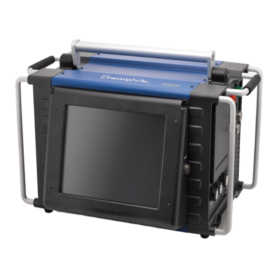
Power Supply User’s Manual This manual contains important information for the safe and effective operation of the Swagelok ® Welding System M200 power supply. Users should read and understand its contents before operating the M200 power supply. - Page 2 M200 Power Supply User’s Manual...
-
Page 3: Table Of Contents
Electrical Requirements ....Setting up the M200 Power Supply ... Installing the Weld Head .... - Page 4 M200 Power Supply Dimensions ... . 101 Use of Extension Cords with the M200 Power Supply ....101 Troubleshooting Weld Status Conditions .
-
Page 5: Safety
Safety Summary Arc welding can be hazardous Read the entire safety information section and M200 Power Supply User’s Manual before using this product Failure to do so can result in serious injury or death Signal Words and Safety Alert Symbols... - Page 6 Welding Society and OSHA Safety and Health Standards, 29 CFR 1910 and 1926, from the U S Government Printing Office The M200 power supply has no internal serviceable parts and should not be disassembled Return the M200 power supply to an authorized Swagelok sales and service representative for service ELECTRIC SHOCK can kill.
- Page 7 M200 Power Supply User’s Manual FUMES AND GASES can be hazardous. Welding produces fumes and gases. Breathing these fumes and gases may be hazardous to your health. Build-up of gases can displace oxygen and cause injury or death. To avoid injury: ■...
- Page 8 ■ Do not weld on closed containers such as tanks, drums, or pipes, unless they are properly prepared in accordance with AWS F4.1. ■ Do not use the M200 power supply to thaw frozen pipes. ■ Do not use extension cords that are in poor physical condition or have insufficient current capacity.
- Page 9 M200 Power Supply User’s Manual CYLINDERS may explode if damaged. Gas cylinders used as part of the orbital GTAW process contain gas under high pressure. If damaged, a cylinder can explode. To avoid injury: ■ Protect compressed gas cylinders from excessive heat, mechanical shocks, slag, open flames, sparks, and arcs.
-
Page 10: M200 Power Supply Warning Label
Do Not Remove, Destroy, or Cover This Label • Pacemaker wearers keep away. • Return to authorized sales and service center for service. For user information contact Swagelok Co. (www.Swagelok.com) ELECTRIC SHOCK can kill. WELDING can cause fire or explosion. -
Page 11: Referenced Documents
M200 Power Supply User’s Manual Referenced Documents 1 AWS F4 1, Recommended Safe Practices for the Preparation for Welding and Cutting of Containers and Piping. American Welding Society, 550 N.W. LeJeune Rd, Miami, FL 33126 (www.aws.org). 2 ANSI Z49 1, Safety in Welding Cutting, and Allied Processes. - Page 12 M200 Power Supply User’s Manual...
-
Page 13: Installation And Setup
M200 Power Supply User’s Manual Installation and Setup... -
Page 14: Description
M200 Power Supply User’s Manual Description The Swagelok Welding System M200 power supply Four USB A version 1.1 ports on the side of the M200 provides precise control of weld current, electrode power supply accept compatible USB hardware, travel speed, and OD shield gas flow to produce such as a USB mouse or keyboard, with no additional consistent and repeatable weld results. - Page 15 M200 Power Supply User’s Manual Electrode connection (red) Work Remote connection pendant (green) connection Printer housing ID shield gas connections OD shield gas connections Auxiliary output Weld head connections connection Fig. 4—M200 Power Supply Right Side...
-
Page 16: Unpacking The M200 Power Supply
Remove the contents of the shipping case (Table 1): Note: Do not store the M200 power 1. Use the handle on the top of the M200 power supply to lift it supply near corrosive materials. out of the case. Place the M200 power supply upright on a Store indoors and cover when not stable surface. -
Page 17: Registration Information
M200 power supply and Swagelok weld heads. Please take a moment to fill out the information listed below. See the rating label on the back of the M200 power supply. (Fig. 5) for the model and serial numbers. -
Page 18: Tools And Accessories Required
230 V (ac) 16 A See Specifications, page 100, for detailed power input and output information. Using Extension Cords Extension cords may be used with the M200 power supply. Extension cords must meet the current capacity specifications in Table 43, page 101. -
Page 19: Setting Up The M200 Power Supply
(printer or accessible. fan/filter side) or when tilted more 2. Make sure the power switch on the left side of the M200 than 15° on its horizontal axis. The power supply is in the ( O ) position. -
Page 20: Installing The Weld Head
M200 Power Supply User’s Manual Installing the Weld Head Weld head The weld head assembly attaches to the right side of the M200 quarter-turn power supply with four separate connectors (Fig. 7) : connector Electrode (red) Weld head quarter-turn connector ■... -
Page 21: Setting Up The Gas Supply System
M200 Power Supply User’s Manual Setting Up the Gas Supply System The M200 power supply has an integral mass flow controller (MFC) to control and monitor the flow of the gas supply system that provides OD shield gas to the weld head. OD shield gas fills the weld chamber to protect the electrode and weld puddle from contaminating elements in the surrounding air. -
Page 22: Powering On The M200 Power Supply For The First Time
Restarting the M200 Power Supply password to allow access to the unit. 1. Power on the M200 power supply by toggling the on/off switch on the left side of the unit to the ( I ) position. -
Page 23: Using The Touch Screen
To enter information, press the field to be filled in. Depending on the information to be entered, a numeric keypad, alphanumeric keyboard, or drop-down menu will appear. A USB mouse and keyboard also can be connected to the M200 power supply for data entry. Numeric Keypad The valid range for the selected parameter will display at the Fig. - Page 24 M200 Power Supply User’s Manual Keyboard Use the onscreen keyboard (Fig. 15) as you would a ■ computer keyboard. To reposition the keyboard, press the gray bar at the top of ■ keyboard and drag it to the new position.
-
Page 25: Operation
This section describes the basic operation of the M200 power supply. Main Menu The Main Menu (Fig. 17) provides access to the M200 power supply’s functions. Select functions by pressing the onscreen button or by using a USB mouse to click on the selection. The Main Menu buttons are described in Table. - Page 26 File load, and save weld procedures. The File mode applies only to weld procedures and does not affect the M200 power supply Setup or Weld Log files. See page 35 for more information about the File screens. The Program screens are used to create new weld Program procedures using Auto Create or Manual Create.
- Page 27 Setup. See Passwords, page 46, for more information. The printer is located on the right side of the M200 Paper Feed power supply, above the weld head connection. Paper Feed advances the paper through the printer.
-
Page 28: Weld Screens
M200 Power Supply User’s Manual Weld Screens The Weld screens (Fig. 21) are used to view and adjust (see Note: Changing the weld procedure Note) the parameters of the active weld procedure. The screen parameters will add “(modified)” to is divided into upper and lower sections. - Page 29 The rotor is a potential pinch The Information tab also displays the Electrode point Change button, which positions the rotor for electrode replacement and prevents the M200 power supply from welding. Note: Electrode Change disables most See the weld head user’s manual for instructions on other M200 power supply buttons.
- Page 30 Example: if the Average Amps for Level 1 is 100 A and the current limit is 50 %, the M200 power supply will not allow an adjustment of Average Amps above 150 A or below 50 A. The factory default for limits is 100 %.
- Page 31 M200 Power Supply User’s Manual Table 7—Weld Lower Section Tabs Process Displays the status and progress of the weld, including tacks, error messages and electrode (Fig. 26) position. Purge Setup Displays the Normal Purge, Blast Purge, and Gas Type fields.
- Page 32 See page 65 for more information about weld procedures using tacks. Summary This tab provides information on the M200 power supply’s Disable, Operational, and Error conditions (Fig. 31) when a weld procedure is loaded. The View button allows a look at the last completed weld in the Weld Log.
- Page 33 M200 Power Supply User’s Manual Table 8—Weld Screen Buttons Check or demonstrate a weld procedure with Test this mode. Press to put the power supply in an alternate operating mode that will not supply current to the electrode. Press again to stop. The current and voltage displays will not operate and the weld counter will not advance.
-
Page 34: Performing A Weld
During welding, the status messages are displayed on the Process tab, along with a time-remaining counter. After the Weld is Complete 1. The M200 power supply will return to the “Ready” state. CAUTION Use gloves or other protective 2. Check the fixture block to confirm that it has cooled before devices if you must handle parts handling. -
Page 35: File Screens
■ File Copy ■ When the File screen opens, the M200 power supply searches the internal memory and a connected USB flash drive. A large number of folders can slow the search process. To reduce the time required, delete unnecessary files or folders in the internal memory and on the USB flash drive. - Page 36 M200 Power Supply User’s Manual Table 9—Load / Save / Print / Delete Tab Buttons Select the weld procedure in the File View pane Print and press Print. Select the weld procedure from the File View View pane and press View. The file preview window will appear showing the weld procedure name, a description, the programmer’s name, and the date...
- Page 37 M200 Power Supply User’s Manual File Copy Tab Folder panes The File Copy tab (Fig. 33) allows the user to copy folders and files between folders in internal memory or to and from a USB flash drive. When the File Copy tab opens, the internal memory and USB Flash Drive (if attached) folders will be shown in both folder panes.
-
Page 38: Program Screens
M200 Power Supply User’s Manual Program Screens The Program screens (Fig. 34) are used to create new weld procedures using Auto Create or Manual Create. Table 11—Program Screen Buttons When you select Auto Create, a dialog box will Auto Create ask you to confirm overwriting the active weld procedure. -
Page 39: Weld Log Screens
M200 Power Supply User’s Manual Weld Log Screens A Weld Log record is saved to internal memory for every completed weld. This feature cannot be disabled, but Weld Log records can be deleted after they are saved to internal memory. - Page 40 Prints the selected Weld Log record. Print Transfers files and folders directly to a PC using a Serial serial cable. M200 power supply serial port settings: Baud rate: 38 400 Data bits: 8 Parity: None Stop bits: 1 Flow control: None...
- Page 41 M200 Power Supply User’s Manual Export / Copy / Delete Tab The Export / Copy / Delete tab (Fig. 38) opens, showing two panes: Internal Memory / USB Flash Drive (left pane) displays the ■ folders in the Internal Memory \ Weld Log and USB Flash Drive \ Weld Log (if drive is connected).
-
Page 42: Setup Screens
M200 Power Supply User’s Manual Setup Screens The Setup screen (Fig. 40) is divided into upper and lower sections. The Upper Section Tabs apply primarily to system parameters: passwords, language, software, etc. The Lower Section Tabs apply primarily to hardware parameters: touch screen, printer, flow control, etc. - Page 43 10, the printer prints after every 10th weld, etc. Operation Allows the user to set some of the M200 power supply functions: (Fig. 42) Jog Speed %: Enables the user to set the speed of the weld head when jogging as a percentage of the weld head full speed.
- Page 44 Fig. 44, Setting Passwords Fig. 45) The owner password is set in the Setup Wizard the first time the M200 power supply is powered on. To set security or programmer passwords: Press the Current Privilege Level button (Fig. 43, ■...
- Page 45 Turns the Alarm on or off. When this function is allows a weld to be performed without on and a weld error occurs, the audible alarm will using the M200 power supply internal sound. The error displays on the Status line and is shield gas flow control Shield gas recorded in the Weld Log.
- Page 46 Enter and confirm the password and press Privilege Level to view the access granted. Press Enter to use the password and log in to the M200 power supply (Fig. 48). If you do not set security and programmer passwords: The M200 power supply will not prompt for a password ■...
-
Page 47: Remote Pendant
M200 Power Supply User’s Manual Remote Pendant The pendant provides remote operation of the primary power supply controls Start, Stop, Home, and Shield Gas. It also displays power supply status indicators On, Ready, Weld, and Error. The pendant is attached to the power supply via a cable and he connector labeled Remote on the right side of the power supply (Fig. -
Page 48: Maintenance
M200 Power Supply User’s Manual Maintenance The M200 power supply has no internal serviceable parts and should not be disassembled. The only field-replaceable WARNING parts are the printer paper and optional fan filter. Contact Do not attempt to service the... -
Page 49: Printer
M200 Power Supply User’s Manual Printer Latches Changing Paper The printer uses thermal paper rolls available from your authorized Swagelok representative. Standard thermal paper rolls available at most office supply stores may also be used. Printer To change the paper roll: cover 1. -
Page 50: Clearing A Paper Jam
M200 Power Supply User’s Manual 5. Place the paper roll on top of the power supply, with the paper coming off the top of the roll. Allow some slack in the paper. Paper roll Note: The paper must be fed through the printer before the spindle is placed in the support bracket. -
Page 51: Installing And Replacing The Optional Fan Filter
Optional Fan Filter The filter is not required for normal power supply operation. It can be purchased for use in dusty environments. To install or replace the optional fan filter in the M200 power supply (Fig. 55): Fan housing door 1. -
Page 52: Weld Parameter Development
34.7 33.7 32.7 During a typical weld, the M200 power supply pulses between High Amps and Low Amps. In this case, the current pulses between the high and the low levels four times per second. The current is at the high level 28 % of the time and at the low level 72 % of the time. -
Page 53: Weld Parameter Changes
Creating a Weld Procedure Guideline A Weld Procedure Guideline is the initial set of weld parameters used to program the M200 power supply for a specific weld job. The M200 power supply Auto Create feature is recommended to generate the weld procedure, but for instances where the work... -
Page 54: Weld Procedure Guideline Worksheets
M200 Power Supply User’s Manual Weld Procedure Guideline Worksheets Table 16—Fractional Butt Weld Procedure Guideline Worksheet Example Based on 1/2 in 0 049 in Entry Step Parameter Tube-Tube 316LV Screen Programmer Weld / Joe Welder Information / Programmer Joint Type Example Tube to tube (Tube–Tube) - Page 55 M200 Power Supply User’s Manual Table 16—Fractional Butt Weld Procedure Guideline Worksheet Example Based on 1/2 in 0 049 in Entry Step Parameter Tube-Tube 316LV Screen For future calculations: High Amp current factors F , and F (see Table 29, page 82) = 2400 = _____ ;...
- Page 56 M200 Power Supply User’s Manual Table 16—Fractional Butt Weld Procedure Guideline Worksheet Example Based on 1/2 in 0 049 in Entry Step Parameter Tube-Tube 316LV Screen Weld Time for all levels = Time (step 20) N (step 18)
- Page 57 M200 Power Supply User’s Manual Table 16—Fractional Butt Weld Procedure Guideline Worksheet Example Based on 1/2 in 0 049 in Entry Step Parameter Tube-Tube 316LV Screen Downslope = Time (step 23) constant = ______ Weld / Total General / Constant: OD <...
- Page 58 M200 Power Supply User’s Manual Table 17— Metric Butt Weld Procedure Guideline Worksheet Example Based on 12 0 1 0 mm Entry Step Parameter Tube-Tube 316LV Screen Programmer Weld / Joe Welder Information / Programmer Joint Type Example Tube to tube (Tube–Tube)
- Page 59 M200 Power Supply User’s Manual Table 17— Metric Butt Weld Procedure Guideline Worksheet Example Based on 12 0 1 0 mm Entry Step Parameter Tube-Tube 316LV Screen For future calculations: High Amp current factors F , and F (see Table 30, page 82) = 87 = _____ ;...
- Page 60 M200 Power Supply User’s Manual Table 17— Metric Butt Weld Procedure Guideline Worksheet Example Based on 12 0 1 0 mm Entry Step Parameter Tube-Tube 316LV Screen Pulse Rate for all levels = Total travel speed (step 19) Weld / ...
- Page 61 M200 Power Supply User’s Manual Table 17— Metric Butt Weld Procedure Guideline Worksheet Example Based on 12 0 1 0 mm Entry Step Parameter Tube-Tube 316LV Screen Downslope = Time (step 23) constant = ______ Weld / Total General / Constant: OD <...
- Page 62 In these cases it is common to add 40 % of the ATW cuff thickness to the fitting wall thickness (Fig. 57). The M200 power supply Auto Create feature calculates this automatically. The worksheets include this step. Arc gap 0.020 in.
- Page 63 M200 Power Supply User’s Manual Socket Welds Note: To fixture, push socket face against All socket welds use a single-pass technique. The arc gap and centering gauge and a 0.015 in. electrode offset parameters are referenced from the socket. (0.38 mm) offset spacer (e.g. feeler The arc gap is 0.010 in.
-
Page 64: Advanced Weld Procedure Techniques
M200 Power Supply User’s Manual Advanced Weld Procedure Techniques The M200 power supply incorporates features that allow adjustments to weld procedures created with using Auto Create, Manual Create, and Single Level Mode programming. These features allow the programmer or owner to adjust the heat input by varying different weld procedure parameters. -
Page 65: Tacks
They are used to hold the joint alignment and joint gap during welding. The M200 power supply will allow up to 20 tacks in Auto Create or Manual Create (Fig. 59). See the Tack Parameter Guideline Worksheet below, for use in conjunction with the Weld Procedure Guideline Worksheets. -
Page 66: Ramp Time
M200 Power Supply User’s Manual Ramp Time Ramp time is time taken at the beginning of a level to allow a gradual amperage change from the arc start current (for the first level) or the previous level’s Low and High Amps settings (for all other levels). -
Page 67: Ramping Up In Level 1
M200 Power Supply User’s Manual Ramping Up in Level 1 Ramping in the first level may be used to slow the startup of the weld to allow controlled heat application, which is required for some materials. Two methods for gradually adding heat to the material in Level 1 are postponed penetration while welding and added rotor delay time before welding. - Page 68 M200 Power Supply User’s Manual Table 21—Level 1 Ramp—Postponed Penetration Guideline Worksheet Table 16 Example Based on (Fractional) 1/2 in 0 049 in (Fractional) or 12 mm 1 0 mm (Metric) Table 17 Tube-Tube 316LV (Metric) Increase Level 1 Time...
-
Page 69: Added Rotor Delay Time Before Welding
M200 Power Supply User’s Manual Added Rotor Delay Time Before Welding This method adds heat before the rotor begins advancing. In this case, full penetration is required before the rotor can advance, but the heat input must be incremental. See Fig. 62 and the Level 1 Ramp Added Rotor Delay Time Guideline Worksheet below, for use in conjunction with the Weld Procedure Guideline Worksheets. - Page 70 M200 Power Supply User’s Manual Table 22—Level 1 Ramp Added Rotor Delay Time Guideline Worksheet Table 16 (Fractional) Example Based on 1/2 in 0 049 in (Fractional) Table 17 or 12 mm 1 0 mm (Metric) (Metric) Tube-Tube 316LV...
-
Page 71: Step Programs For Multilevel Weld Procedures
Calculations for Weld Time change significantly for a Step Program. Use the following Step Program Parameter Guideline Worksheets to generate the necessary M200 power supply plug-in values. The example fractional tube size is 2.0 in. OD and 0.109 in. - Page 72 M200 Power Supply User’s Manual Table 23—Fractional Step Program Parameter Guideline Worksheet Example Based on 2 0 in 0 109 in Entry Step Parameter Tube-Tube 316LV Screen Programmer Weld / Joe Welder Information / Programmer Joint Type Example Tube to tube (Tube–Tube)
- Page 73 M200 Power Supply User’s Manual Table 23—Fractional Step Program Parameter Guideline Worksheet Example Based on 2 0 in 0 109 in Entry Step Parameter Tube-Tube 316LV Screen For future calculations: High Amp current factors F , and F (see Table 29, page 82) = 460 = _____ ;...
- Page 74 M200 Power Supply User’s Manual Table 23—Fractional Step Program Parameter Guideline Worksheet Example Based on 2 0 in 0 109 in Entry Step Parameter Tube-Tube 316LV Screen For future calculations: Weld Time total for single pass: Average speed = (High Amp Speed [step 23] Width [step 15]) (0.26 ...
- Page 75 M200 Power Supply User’s Manual Table 23—Fractional Step Program Parameter Guideline Worksheet Example Based on 2 0 in 0 109 in Entry Step Parameter Tube-Tube 316LV Screen For Wall ≤ 0.083 in. Weld / General / Rotor Delay Time = Wall (step 5) 40 = ______ Start field _____ ...
- Page 76 M200 Power Supply User’s Manual Table 24—Metric Step Program Parameter Guideline Worksheet Example Based on 54 0 mm 2 6 mm Entry Step Parameter Tube-Tube 316LV Screen Programmer Weld / Joe Welder Information / Programmer Joint Type Example Tube to tube (Tube–Tube)
- Page 77 M200 Power Supply User’s Manual Table 24—Metric Step Program Parameter Guideline Worksheet Example Based on 54 0 mm 2 6 mm Entry Step Parameter Tube-Tube 316LV Screen For future calculations: High Amp current factors F , and F (see Table 30, page 82) = 18 = _____ ;...
- Page 78 M200 Power Supply User’s Manual Table 24—Metric Step Program Parameter Guideline Worksheet Example Based on 54 0 mm 2 6 mm Entry Step Parameter Tube-Tube 316LV Screen For future calculations: Weld Time total for single pass: Average speed = (High Amp Speed [step 23] Width [step 15]) (0.24 ...
- Page 79 M200 Power Supply User’s Manual Table 24—Metric Step Program Parameter Guideline Worksheet Example Based on 54 0 mm 2 6 mm Entry Step Parameter Tube-Tube 316LV Screen For Wall ≤ 2.1 mm Weld / General / Rotor Delay Time = Wall (step 5) 1.6 = ______ Finish field _____ ...
-
Page 80: Weld Parameter Guideline Worksheet Reference Data
M200 Power Supply User’s Manual Weld Parameter Guideline Worksheet Reference Data Table 25 —Wall Thickness and Arc Gap Material Thickness Arc Gap 0.010 to 0.020 0,03 to 0,51 0.020 0,51 0.021 to 0.030 0,52 to 0,86 0.025 0,64 0 031 to 0.045 0,87 to 1,17 0.030... - Page 81 M200 Power Supply User’s Manual Table 27—ID Purge Gas Flow Rate and Pressure, Fractional Dimensions Minimum Pressure ➁➂ Tube Wall ID Purge Restricter Size Thickness Flow Rate ➀ Size ➃ inches std ft of water torr 1/16 0.015 7 to 9 13 to 16.8...
- Page 82 M200 Power Supply User’s Manual Table 29—Fractional High Amps Current Factors and Travel Speeds Outside Diameter, in. Travel High Amps Current Factors Wall Speed Nominal Actual Nominal Tube Size Pipe Size in./min 0.010 to 0.020 1400 1/16 0.063 to 0.124 —...
- Page 83 M200 Power Supply User’s Manual...
-
Page 84: Single Level Mode Operation
In Single Level Mode, single level weld procedure guidelines developed on previous power supplies can be entered using the M200 power supply touch screen. Single Level Mode operation enables the user to enter either single pass or multiple pass weld procedure guidelines. Single Level procedures can be entered manually or by using the Program >... -
Page 85: Single Level Timing-Control Group
Fig. 64— Single Level Timing-Control Note: A minimum of 10 seconds prepurge is Group recommended for all Swagelok weld heads. If weld head extension cables are used, add one second for each foot of extension cable. Weld Time is the actual welding time in seconds at the ■... -
Page 86: Single Level Weld Process Buttons
The buttons function as follows: Positions the rotor for electrode replacement and Electrode Change prevents to the M200 power supply from welding. See the weld head user’s manual for instructions on electrode replacement. After replacing the electrode, press Electrode Change again. The rotor will move the electrode back to the true home position. -
Page 87: Single Level Status Indicator Lights
Most of the indicators light during the welding process to show the control sequence executed by the M200 power supply. The control sequence is affected by the values entered into the timing-control group. Weld Head indicates the weld head is connected. -
Page 88: Single Level Weld Procedure Guidelines
M200 Power Supply User’s Manual Single Level Weld Procedure Guidelines These Single Level Weld Procedure Guidelines show suggested Note: The M200 power supply Auto weld parameter settings based on: Create feature can be used to generate a one-level, multipass Swagelok weld head used ■... - Page 89 M200 Power Supply User’s Manual...
- Page 90 M200 Power Supply User’s Manual...
- Page 91 M200 Power Supply User’s Manual...
- Page 92 M200 Power Supply User’s Manual...
- Page 93 M200 Power Supply User’s Manual...
- Page 94 M200 Power Supply User’s Manual...
- Page 95 M200 Power Supply User’s Manual...
-
Page 96: Evaluating Weld Quality
M200 Power Supply User’s Manual Evaluating Weld Quality Identifying Proper Welds Figure 68 illustrates an acceptable weld: continuous full penetration from the outside diameter (OD) to the inside diameter (ID); a crown on the OD; and minimal weld bead convexity on the ID. -
Page 97: Improper Welds
M200 Power Supply User’s Manual Improper Welds The following weld examples show how changes in weld parameters affect weld shape. The reference weld (Fig. 70 and 71) was made using a 316L stainless steel tube with a 1/2 in. OD and 0.049 in. wall thickness, in accordance with the weld parameter settings shown below: Fig. -
Page 98: Increased Id Convexity And Weld Bead Width
M200 Power Supply User’s Manual Increased ID Convexity and Weld Bead Width Increased ID convexity and weld bead width can be caused by several improper weld procedure settings. All of the examples shown below result from increased arc intensity and, consequently, heat input, resulting in increased ID convexity and weld bead width. - Page 99 M200 Power Supply User’s Manual...
-
Page 100: Specifications
M200 Power Supply with 115 V Input The rated output of the M200 power supply is available when connected to a 230 V / 20 A branch circuit. When connected to a branch circuit with a lower voltage, lower welding current and duty cycle must be used. An output guide is provided below. -
Page 101: M200 Power Supply Cycle Times
The balance of the cycle is required for cooling. The industry standard is a 10-minute duty cycle. The weld and idle times for several 10-minute duty cycle ratings are shown in Table 41. Table 41—M200 Power Supply 10-Minute Cycle Times Duty Maximum... -
Page 102: Troubleshooting
M200 Power Supply User’s Manual Troubleshooting This section contains troubleshooting guidelines for the M200 power supply and software, including: weld status conditions ■ weld system hardware and weld process problems ■ power supply repair. ■ Weld Status Conditions Disable Disable conditions must be corrected before a weld can be executed. - Page 103 M200 Power Supply User’s Manual Table 44—Disable Conditions Disable Message Description Remedy Welding can continue once the M200 power supply resets. Using 230 V (ac) would prevent this error. An AC input error was detected. The weld The M200 power supply...
-
Page 104: Operational
M200 Power Supply User’s Manual Operational Operational conditions should be noted, but the weld may proceed with discretion. A W: on the status line indicates an operational condition (Fig. 83). Operational conditions are recorded in the Weld Log if the condition is not corrected before starting the weld. - Page 105 M200 Power Supply User’s Manual Table 45—Operational Conditions Operational Message Description Remedy W: Short The prepurge time is set Set prepurge time for prepurge for less than 5 seconds. If longer than 5 seconds, the Shield Gas button on or press the Shield Gas...
-
Page 106: Weld Errors
M200 Power Supply User’s Manual Weld Errors Weld errors indicate problems that occurred during the weld process. “Weld completed” or “Weld not completed” will be displayed on the status line and on the summary screen Fig. 84). A description of the error will be displayed in a dialog box, and the alarm will sound if the alarm function has been turned on (see Table 15, page 45). - Page 107 M200 Power Supply User’s Manual Table 46—Weld Error Conditions Weld Error Message Description Remedy Misfire The arc was not Check the arc gap setting, established. electrode, and fixture. Power source The input current (ac) is Welding can continue AC overcurrent...
-
Page 108: Weld System Hardware And Weld Process Problems
M200 Power Supply User’s Manual Weld System Hardware and Weld Process Problems Repair / Replacement Instructions Certain remedies require a component, such as a weld head, to be disassembled, cleaned, or replaced. For user maintenance weld procedures, see the Maintenance section of the weld head user’s manual (www.swagelok.com). - Page 109 M200 Power Supply User’s Manual Table 48—Weld Head Symptom Cause Remedy Note: See the Maintenance section of Rotor does Weld head connector is Check that the weld head the weld head user’s manual for not return to not fully engaged.
- Page 110 M200 Power Supply User’s Manual Table 48—Weld Head Symptom Cause Remedy Note: See the Maintenance section of Erratic rotor Weld spatter on gears. Inspect the rotor the weld head user’s manual for rotation / primary, secondary, and more information about correcting speed control.
- Page 111 M200 Power Supply User’s Manual Table 49—Electrode Symptom Cause Remedy Material Electrode touched the Replace electrode and found on the weld puddle. check arc gap setting. electrode tip. Check work pieces for out of roundness. Weld puddle protrusion. Check ID purge gas flow rate for excessive back pressure.
- Page 112 M200 Power Supply User’s Manual Table 50—Fixture Block Symptom Cause Remedy When closing The latch is not inserted Reinsert the latch into the the fixture into the fixture block side side plate until it rests block side plate completely. against the latch pin.
- Page 113 M200 Power Supply User’s Manual Table 51—Welding Process Symptom Cause Remedy Arc fails to Incorrect arc gap setting. Reset the arc gap with the start. arc gap gauge. Excessive purge gas flow. Reduce flow to the value shown on the weld procedure guideline.
- Page 114 M200 Power Supply User’s Manual Table 51—Welding Process Symptom Cause Remedy Inside diameter Insufficient ID purge gas. Increase ID purge gas discoloration. flow rate and prepurge time. Contaminants in the ID Increase prepurge time. purge line. Check the gas source for low pressure.
- Page 115 M200 Power Supply User’s Manual Table 51—Welding Process Symptom Cause Remedy Incomplete Insufficient heat Compare the power inside diameter input. supply setting to the penetration. weld procedure guideline being used. Adjust weld parameters as necessary. Incorrect weld procedure Compare the material wall guideline.
-
Page 116: Power Supply Repair
M200 Power Supply User’s Manual Power Supply Repair If the M200 power supply needs to be repaired, contact your authorized Swagelok representative. You will need to provide: serial and model number of the unit ■ complete description of the application ■... - Page 117 M200 Power Supply User’s Manual...
-
Page 118: Glossary
Duty cycle The percentage of time during a 10 minute period that the M200 power supply can operate at a given average current and voltage output setting. GTAW... - Page 119 M200 Power Supply User’s Manual Heat input The heat conducted into the weld during the weld cycle. Typically expressed in joules or kilojoules. High amps The maximum current level generated during the weld process. Also called impulse current. High amp speed...
- Page 120 Power supply The device that produces the electrical power for the welding process. The M200 power supply is a constant-current power supply. Prepurge The amount of time the OD shield gas is applied before the arc start.
- Page 121 M200 Power Supply User’s Manual Step program A type of weld procedure in which the rotor speed is different between the high amps pulse time and the low amps pulse time. The rotor speed may vary from zero to the weld head’s maximum revolutions per minute.
-
Page 122: Swagelok Embedded System End User License Agreement
SOFTWARE AND FIRMWARE: Unless otherwise provided in a Swagelok for any losses sustained as a result of USER’s failure to comply separate Swagelok or third-party license agreement, Swagelok warrants with U.S. or foreign import and export laws, rules or regulations in for a period of 1 year from the date of shipment that the media on which connection with the Product, Embedded System or components thereof. - Page 123 M200 Power Supply User’s Manual...
-
Page 124: The Swagelok Limited Lifetime Warranty
Warranty Information Swagelok products are backed by The Swagelok Limited Lifetime Warranty. For a copy, visit swagelok.com or contact your authorized Swagelok representative. Swagelok—TM Swagelok Company Microsoft, Excel, Access—TM Microsoft Corporation © 2007–2014 Swagelok Company Printed in U.S.A., AGS November 2014, R3...
Need help?
Do you have a question about the M200 and is the answer not in the manual?
Questions and answers