Table of Contents
Advertisement
TABLE OF CONTENTS
1 Safety Precautions----------------------------------------------- 3
2 Specifications ----------------------------------------------------- 4
2.1. Product Specifications------------------------------------ 4
2.2. Name Plate-------------------------------------------------- 4
3 Technical Descriptions ----------------------------------------- 5
3.1. Twinjet Information ---------------------------------------- 5
4 Location of Controls and Components ------------------- 6
5 Installation Instructions ---------------------------------------- 7
5.1. Moving and Installing ------------------------------------- 7
5.2. Detergent Box Group ------------------------------------- 8
6 Operating Instructions------------------------------------------ 9
6.1. LCD Screen, Function Buttons & Knobs ------------ 9
6.2. Program List ------------------------------------------------ 9
6.3. Program Details-------------------------------------------10
6.4. Program Details with Half Load Defection ---------10
6.5. Child Lock -------------------------------------------------- 11
7 Test Mode ----------------------------------------------------------12
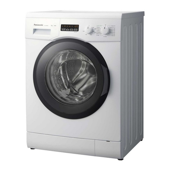
Drum Type Washing Machine
Model No.
Model No.
Model No.
Model No.
Product Color : White
Destination
PAGE
7.1. Autotest----------------------------------------------------- 12
8 Service Mode ----------------------------------------------------- 14
8.1. Service Autotest ------------------------------------------ 14
8.2. Failure Codes --------------------------------------------- 15
9 Troubleshooting Guide --------------------------------------- 16
10 Disassembly and Assembly Instructions--------------- 17
10.1. Torque Values--------------------------------------------- 17
10.2. Top Plate --------------------------------------------------- 18
10.3. Door --------------------------------------------------------- 18
10.4. Spring Wire ------------------------------------------------ 20
10.5. Detergent Drawer ---------------------------------------- 20
10.6. Control Panel---------------------------------------------- 21
10.7. Kick Plate -------------------------------------------------- 22
10.8. Front Panel ------------------------------------------------ 22
10.9. Upper Support Bracket --------------------------------- 24
10.10. Detergent Drawer Housing ---------------------------- 24
10.11. Power Cable Group and Parasite Filter ------------ 25
© Panasonic Corporation 2011 Unauthorized copy-
ing and distribution is a violation of law.
Order No. VES1104001CE
NA-148VB3
NA-128VB3
NA-147VB3
NA-127VB3
: Germany, Spain, France, Italy, Belgium,
Ireland, United Kingdom
PAGE
Advertisement
Table of Contents

Related Manuals for Panasonic NA-148VB3


Summary of Contents for Panasonic NA-148VB3
-
Page 1: Table Of Contents
10.9. Upper Support Bracket --------------------------------- 24 6.5. Child Lock -------------------------------------------------- 11 10.10. Detergent Drawer Housing ---------------------------- 24 7 Test Mode ----------------------------------------------------------12 10.11. Power Cable Group and Parasite Filter ------------ 25 © Panasonic Corporation 2011 Unauthorized copy- ing and distribution is a violation of law. - Page 2 12 Dimensions ------------------------------------------------------- 43 13 Wiring Connection Diagram --------------------------------- 44 13.1. Wiring Diagram NA-127VB3 and NA-147VB3 ---- 44 13.2. Wiring Diagram NA-128VB3 and NA-148VB3 ---- 46 14 Exploded View and Replacement Parts List ----------- 48 14.1. Control Panel Parts -------------------------------------- 48 14.2.
-
Page 3: Safety Precautions
1 Safety Precautions... -
Page 4: Specifications
2 Specifications 2.1. Product Specifications NA-148VB3 NA-128VB3 NA-147VB3 NA-127VB3 Product Type Front Loader Front Loader Front Loader Front Loader Capacity 8 kg 8 kg 7 kg 7 kg Max Spin Speed 1400 r/min 1200 r/min 1400 r/min 1200 r/min Drum Volume... -
Page 5: Technical Descriptions
3 Technical Descriptions 3.1. Twinjet Information 1. Twinjet system is designed to obtain a better washing performance by directly injecting water with detergent using a recirculation system and two nozzles connected to it. With twinjet system, water consumption is decreased by 30%, energy consumption is decreased by 10% and washing time is decreased by 15%. -
Page 6: Location Of Controls And Components
4 Location of Controls and Components... -
Page 7: Installation Instructions
5 Installation Instructions 5.1. Moving and Installing 5.1.1. Removal of Transportation Screw 5.1.2. Foot Adjustment 1. Transportation screws, which are located at the back side 1. Do not install machine on rugs or similar surfaces. of the machine, must be removed before running the 2. -
Page 8: Detergent Box Group
5.2. Detergent Box Group 5.1.4. Water Supply Connection 1. The washing machine is supplied with a single (cold) water inlet. 2. To prevent leakage from the connection joints, a rubber washer is included in the hose packing. Fit this washer at the end of water inlet hose on the tap side. -
Page 9: Operating Instructions
6 Operating Instructions 6.1. LCD Screen, Function Buttons & Knobs Program selector 16 programs including ON/OFF. Switch 1, Start / Pause Switch 2, Temperature Selection Switch 3, Delay Time Function Switch 4, Extra Rinse PT speed potentiometer Switch 1- Start/ Pause Led Temperature Function Button Led Delay Time Function Button Led Extra Rinse Function Button Led... -
Page 10: Program Details
6.3. Program Details NA-148VB3 NA-128VB3 Programmes Temperature Available Program Energy Water Temperature Duration (min)* (kwh)* Consumption (L)* Cotton Cold - 90 0,92 Cotton Eco Cold - 60 0,76 Cotton PreWash Cold - 90 0,98 Easy Care Cold - 60 0,60... -
Page 11: Child Lock
6.5. Child Lock Activation 1. Press the fourth function button for 4-5 seconds. 2. The Child Lock Symbol is appeared on the LCD display. Deactivation 1. Press the fourth function button for 4-5 seconds. 2. The Child Lock Symbol is deleted on the LCD display. -
Page 12: Test Mode
7 Test Mode 7.1. Autotest 1. After selecting spin speed to maximum, select the program 3 (Cotton Eco). 2. While pressing Extra Rinse button, Change position of the third to second and release the Extra rinse button immediately 3. Auto test starts. -
Page 14: Service Mode
8 Service Mode 8.1. Service Autotest 1. Set program knob at Cotton Eco after selection spin speed to max. 2. While pressing the T °C button, change position of the third to second, and remove the T °C button within 1 second. During test [SAU] is visualized on display : LD1 Start / Pause Button LED →... -
Page 15: Failure Codes
8.2. Failure Codes Error Indication Error Number Indication For User Indication For Service Yes/No Yes/No Door is not locked Door is unlocked during programme Lack of water Pump failure Overflow NTC or Heater Failure Motor Failure - 1 (Tachometer open-short circuit or motor connector is disconnected) Motor Failure - 2 (triac short circuit) Out of voltage... -
Page 16: Troubleshooting Guide
9 Troubleshooting Guide All repairs which must be done on the machine should be done by authorized agents only. When a repair is required for machine or you are unable to eliminate the failure with the help of the information given below: •... -
Page 17: Disassembly And Assembly Instructions
10 Disassembly and Assembly Instructions 10.1. Torque Values ASSEMBLY LOCATION PART NAME SAP CODE TORQUE TORQUE TORQUE MIN. (Nm) NOM. (Nm) MAX. (Nm) Parasite Filter - Cabinet Assembly ISO 7049 ST 4.2X9.5 R Underhead Serrated 35001817 2,34 2,60 2,86 Pressure Switch Supporting Plastic - SCREW 4X12 PAN HEAD WITH COLLAR UNDER 37013513 1,44... -
Page 18: Top Plate
10.2. Top Plate 1. Remove two screws that fix the top-plate at the back. 2. Pull the door up. 2. Push the top-plate back and pull it up. 3. Remove screws that fix the door group. 10.3. Door 1. Remove two screws that fix the door. (by using the T25) - Page 19 4. Put the door outside plastic with helping screwdriver as it 7. Remove the door handle as it is shown in the picture. is shown in the picture. 8. Remove the door handle pin as it is shown in the pictures. 5.
-
Page 20: Spring Wire
10.4. Spring Wire 10.5. Detergent Drawer 1. First remove the spring wire fixing the tub bellows seal by 1. Remove the detergent drawer and pull it up carefully. using the small size screwdriver. Pull the tub bellows seal as it is shown in the picture. 2. -
Page 21: Control Panel
10.6. Control Panel 4. Remove connectors as it is shown in the picture. 1. Remove the screw which fix the control panel to the front panel. 5. Remove electronic card cover as it is shown in the pic- tures by using small screwdriver. 2. -
Page 22: Kick Plate
10.7. Kick Plate 10.8. Front Panel 1. Remove the right part of the kick plate as it is shown in 1. Remove two screws fixing the front panel at the bottom as the picture. it is shown in the picture by using T25. 2. - Page 23 3. Remove the tub bellows seal as it is shown in the pic- 6. Remove twinjet t-elbow fixing front panel at the upper as it tures. is shown in the picture. 4. Remove two screws fixing front panel at the upper as it is 7.
-
Page 24: Upper Support Bracket
10.9. Upper Support Bracket 10.10. Detergent Drawer Housing 1. Remove two screws fixing the body group at the front as it 1. Remove the tub seal clamp by using the pliers, which is is shown in the picture. attached to the detergent drawer housing. 2. -
Page 25: Power Cable Group And Parasite Filter
4. Remove the detergent drawer housing assembly. 3. Pull the power cable group up as it is shown in the pic- ture. 4. Remove parasite filter fixing body group as it is shown in 10.11. Power Cable Group and Para- the picture. -
Page 26: Electronic Pressure Switch (Eps)
10.12. Electronic Pressure Switch 10.13. Door Lock (EPS) 1. Remove the connector that is connected to the door lock. 1. Remove the connector that is connected to the EPS. 10.14. Pump Motor 2. Pull the EPS upward to remove as it is shown in the pic- ture. -
Page 27: Front Counterweight
10.15. Front Counterweight 3. Remove the connector that is connected to the pump motor. 1. Remove four screws fixing the front counterweight on the front. (Box wrench size 13 mm) 4. Remove four screws fixing the pump motor. 2. Pull the counterweight back. 5. -
Page 28: Twinjet System
2. Remove one nut fixing the heater slightly. (box wrench 2. Remove the two twinjet hoses from the gasket. size 8 mm) 3. Remove screw fixing the circulation pump. (using T20) 3. Hold the heater and pull it out. 4. After lay down the washer on its rear side, and press the pawl inward. -
Page 29: Tub Bellows Seal
5. Remove the circulation pump. 2. Hold the tub bellows seal and gasket-body fixing spring together, and pull them up. 6. Remove the connector that is connected to the circulation pump. 10.19. Transport Screw 1. Remove four transport screws. (box wrench size 10 mm) 10.18. -
Page 30: Upper Counterweight
10.20. Upper Counterweight 2. Cut the five lead wire holders as shown the pictures. 1. Remove two screws fixing the upper counterweight by using box wrench size 13 mm. 3. Remove the four screws fixing the spring hanger sheet 2. Remove the upper counterweight. iron. -
Page 31: Shock Absorber Pin
10.22. Shock Absorber PIN 2. Remove the driven pulley it is shown the picture. 1. Remove two pins fixing the shock absorber as shown in the picture. 10.25. Motor 1. Remove the four screws fastening the motor under the 10.23. Belt tub by using T40. -
Page 32: Tub Entrance With Bellow Hose
10.26. Tub Entrance with Bellow Hose 10.28. Tub 1. Remove the tub entrance with bellow hose. 1. Remove twenty four screws fixing tub using box wrench size 8 mm. 10.27. Pressure Switch Hose Group 1. Remove screw fixing the pressure switch water reservoir. 10.29. -
Page 33: Measurements And Adjustments
11 Measurements and Adjustments 11.1. Drain Pump Drain pump is both a mechanical and electrical component which is used to drain water inside the washing machine. It has an synchronous motor inside. For better performance mainte- nance, pump filter should be cleaned regularly. 11.1.3. -
Page 34: Circulation Pump
11.2. Circulation Pump The component is used for circulation of water inside the drum in order to increase washing performance. 11.2.3. Component Controlling By Con- nection Measurement 11.2.1. Technical Features Nominal voltage 220 - 240 V Frequency 50 Hz 169,5 Ω (±5 %) Resistor (coil) 11.2.2. -
Page 35: Resistance
230 V Nominal power 2000 W (±5 %) 24,8 ±5% Ω (for NA-127VB3 and NA-147VB3) Resistance 25,2 ±5% Ω (for NA-128VB3 and NA-148VB3) Thermal fuse 2 - sided 11.3.2. Checking of Component Check the resistance value on the component with multimeter as shown in below pictures. -
Page 36: Ntc
11.4. NTC 11.4.2. Checking of Component Check the resistance value on the component with multimeter Component which sends signals to PCB about the water tem- as shown in below pictures. perature inside the tub. The Resistance (Ohm) value of the NTC decreases as the tem- perature increases. -
Page 37: Valve
11.5. Valve Valve is an electrical and mechanical component which is designed to take water from the network system into the wash- ine machine. It is operated by PCB card. 11.5.3. Component Controlling By Con- nection Measurement 11.5.1. Technical Features Nominal voltage 220 - 240 V Nominal power... -
Page 38: Electronic Pressure Switch (Eps)
11.6. Electronic Pressure Switch (EPS) 11.6.1. Technical Features Electromagnetic field occurs as a result of the vibration of the membrane which is under pressure in the coil. The nucleus part is moved up and down by the electromagnetic field. The water level is regulated by the frequency which is controlled by the PCB and changes according to the movement of the nucleus part. -
Page 39: Motor (For Na-127Vb3 And Na-147Vb3)
11.7. Motor (For NA-127VB3 and NA-147VB3) The washing machine has an asynchronous motor. It is controlled by the PCB. It is essential to check the motor for correct diagnosis and quick servicing. In the below picture, socket points on the motor is shown to measure with multimeter. -
Page 40: Motor (For Na-128Vb3 And Na-148Vb3)
11.8. Motor (For NA-128VB3 and NA-148VB3) The washing machine has an asynchronous motor. It is controlled by the PCB. It is essential to check the motor for correct diagnosis and quick servicing. In the below picture, socket points on the motor is shown to measure with multimeter. -
Page 41: Door Lock
11.9. Door Lock 11.9.2. Checking of Component Check the resistance value on the component with multi-meter Door lock is activated at the beginning of the program in order as shown in below figures. to prevent the door from opening. Locking is generated by sup- Resistance value on the (PTC overload + solenoid) should be plying power to PTC-bimetal, after max 6sec (220V), the 240Ω... - Page 42 11.9.3. Component Controlling By Con- nection Measurement This socket shows the connection between terminal 3-4 (See wiring diagram (***) above). The resistance read from terminal 3-4 is the resistance of PTC overload plus resistance of sole- noid.
-
Page 43: Dimensions
12 Dimensions... -
Page 44: Wiring Connection Diagram
13 Wiring Connection Diagram 13.1. Wiring Diagram NA-127VB3 and NA-147VB3... -
Page 46: Wiring Diagram Na-128Vb3 And Na-148Vb3
13.2. Wiring Diagram NA-128VB3 and NA-148VB3... -
Page 48: Exploded View And Replacement Parts List
14 Exploded View and Replacement Parts List 14.1. Control Panel Parts 14.1.1. Exploded View Control Panel Parts... - Page 49 AXW147B-8134 NA-128VB3 FRANCE AXW147B-8156 NA-128VB3 SPAIN AXW147B-8170 NA-128VB3 ITALY AXW147B-8104 NA-147VB3 BELGIUM AXW147B-8118 NA-147VB3 GERMANY AXW147B-0669 NA-147VB3 IRELAND AXW147B-8110 NA-148VB3 BELGIUM AXW147B-8124 NA-148VB3 GERMANY AXW147B-8173 NA-148VB3 ITALY AXW147B-0692 NA-148VB3 IRELAND CONTROL PANEL AXW1J-58079 NA-127VB3 BELGIUM AXW1J-58126 NA-127VB3 FRANCE AXW1J-58143 NA-127VB3...
-
Page 50: Front Panel Parts
Part Name Converted Quantity Model Remarks Panasonic Parts No. BODY GROUP PAINTED AXW1AB-37787 NA-127VB3 - NA-147VB3 AXW1AB-27916 NA-128VB3 - NA-148VB3 UPPER TRAY GROUP AXW11N-27279 NA-127VB3 - NA-147VB3 AXW11N-27281 NA-128VB3 - NA-148VB3 FRONT PANEL GROUP AXW1BB-42790 PLINTH GROUP AXW22S-23758 PLINTH AXW130-23756... -
Page 51: Washing Group Parts
14.3. Washing Group Parts 14.3.1. Exploded View Washing Group Parts... - Page 52 Part Name Converted Quantity Model Remarks Panasonic Parts No. REAR TUB GROUP AXW12A-89470 NA-127VB3 - NA-147VB3 AXW12A-37596 NA-128VB3 - NA-148VB3 FRONT TUB AXW32G-59330 NA-127VB3 - NA-147VB3 AXW32G-59372 NA-128VB3 - NA-148VB3 DRUM GROUP AXW22B-33867 NA-127VB3 - NA-147VB3 AXW22B-57607 NA-128VB3 - NA-148VB3...
-
Page 53: Circulation Group Parts
14.4.1. Exploded View Circulation Group Parts 14.4.2. Circulation Group Replacement Parts List Safety Ref. No. Part Name Converted Quantity Model Remarks Panasonic Parts No. TWIN JET HORN/LEFT AXWTJH-25993 TWIN JET HORN/RIGHT AXWTJH-25992 SCREW 4X14 PAN HEAD TYPE 2 AXWSS5-07242 TWIN JET T-ELBOW AXWTJT-25561 HANDCUFFS 20.2 DIA... -
Page 54: Detergent Drawer Group Parts
14.5. Detergent Drawer Group Parts 14.5.1. Exploded View Detergent Drawer Group Parts... - Page 55 DETERGENT DRAWER AXW1DD-19135 SIPHON COVER AXW1SC-19134 PLASTIC HOSE HANDCUFFS AXW1PH-04189 VALVE-DETERGENT BOX HOSE AXW1VD-04536 NA-127VB3 - NA-147VB3 AXW1VD-04537 NA-128VB3 - NA-148VB3 VALVE-DETERGENT BOX HOSE AXW1VD-07796 NA-127VB3 - NA-147VB3 AXW1VD-07797 NA-128VB3 - NA-148VB3 VALVE(TWO EXIT) AXW1VT-13042 DETERGENT BOX GROUP AXW21D-60571 NA-127VB3 - NA-128VB3...
-
Page 56: Pressure Switch Hose Group Parts
14.6.2. Pressure Switch Hose Group Replacement Parts List Safety Ref. No. Part Name Converted Quantity Model Remarks Panasonic Parts No. TUB EXIT BELLOW HOSE WITH BALL AXW1250-4954 PRESSURE SW WATER RESERVOIR AXW1PS-20089 PRESSURE SWITCH HOSE AXW1PS-19319 TUB EXIT BELLOW HOSE BALL... -
Page 57: Body Group Parts
14.7. Body Group Parts 14.7.1. Exploded View Body Group Parts... - Page 58 DRAIN HOSE AXW1DH-08945 ELECTRONIC PRESSURE SENSOR AXW1EP-06187 EMI FILTER AXW2EF-15002 CBL HARN AXW14B-13279 NA-127VB3 - NA-147VB3 AXW14B-13277 NA-128VB3 - NA-148VB3 CABLE HARNESS HOLDER PLS AXW1CH-22148 TUB SPRING AXW3441-5307 NA-127VB3 - NA-147VB3 AXW3441-4888 NA-128VB3 - NA-148VB3 HANGER SPRING SHEETIRON PLS. AXW1HS-16727...
-
Page 59: Porthole Group Parts
14.8. Porthole Group Parts 14.8.1. Exploded View Porthole Group Parts 14.8.2. Porthole Group Replacement Parts List Safety Ref. No. Part Name Converted Quantity Model Remarks Panasonic Parts No. SCR 3.5X16PAN.HE.W COL.CR.RE. AXWSS7-08715 INNER DOOR PLASTIC AXW1DP-55347 HINGE II-M5 AXW192-15559 HINGE BUSHING II AXW192-23907... -
Page 60: Accessories
Panasonic Parts No. PROGRAM LABEL AXW90PL-0995 SERVICE LIST GUARANTEE AXW9911-9381 REFERENCE SHEET AXW90RS-9387 USER'S MANUEL AXW4F-39392 ENERGY LABEL AXW90EL-3397 NA-128VB3 AXW90EL-3395 NA-127VB3 AXW90EL-3396 NA-147VB3 AXW90EL-3398 NA-148VB3 LIQUID DETERGENT LEVEL PLATE AXW90LD-9158 DRAIN HOSE COAT RACK AXW90HC-0601 TRANSPORT SCREW STOPPER AXW1TS-14437...