
Related Manuals for Body Flex Sports Body Rider BRT3980

Summary of Contents for Body Flex Sports Body Rider BRT3980
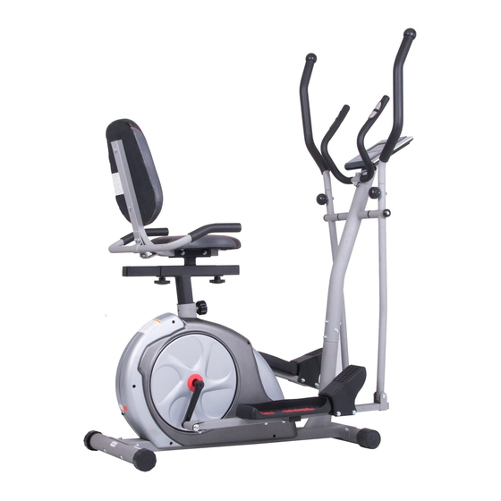
- Page 1 3-in-1 Trio Trainer BRT3980/3880 * This item is for consumer use only and it is not meant for commercial use. OW N ER ’S M A N UA L...
- Page 2 PLEASE KEEP THESE INSTRUCTIONS FOR FUTURE USE & REFERENCE. DO NOT DISCARD. WARNING: SERIOUS INJURIES AND EVEN DEATH CAN OCCUR IF THE PROPER SAFETY PRECAUTIONS ARE NOT FOLLOWED. The diagram below highlights and reviews many of the important Safety and Warning labels also found on the unit.
-
Page 3: Customer Support
Please read this manual carefully before commencing the Body Flex Sports warrants your product for assembly of your product or starting to exercise. a period of 1 year for the frame and 90 days on all parts if the item is used for the intended •... - Page 4 Hardware List The following hardware is used to assemble your unit. Please take a moment to familiarize yourself with these items. Please note, most of these parts are already pre-assembled on your unit. Do not be alarmed if you see parts on this page that are not included in your hardware packet.
-
Page 5: Table Of Contents
Parts Listing Description Description Main Frame Washer (M8) Center Post Spring Washer (M8) Left Pedal Tube D Shape Washer (19 mm) Right Pedal Tube Special Washer (ID19 mm) Left Coupler Bar Special Washer (ID16 mm) Right Coupler Bar Bushing Cushion Frame Spring Loaded Knob (M16) Horizontal Seat Cushion Bar Knob (M8) -
Page 6: Exploded Diagram
Exploded Diagram The following diagram is provided to help you familiarize yourself with the parts and hardware that will be used during the assembly process. Please note that not all of the parts and hardware you see here will be used while you are assembling the machine because some of these items are already pre-installed. -
Page 7: Main Frame
Assembly Instructions A s s e m b l y S t e p 1 Hardware Required FRONT STABILIZER ASSEMBLY BOLTS Using the drawing below for reference, secure the Front Stabilizer (#14) to the Main Frame (#01) using a total of two Carriage Bolts (#20), two Arc Washers #20. -
Page 8: Center Post
Assembly Instructions A s s e m b l y S t e p 2 Hardware Required WIRE CONNECTIONS BOLTS Connect the Main Sensor Wire (Lower)(#52) to the Main Sensor Wire (Upper) (#51). #31. Screw (M8x15 mm) CENTER POST ASSEMBLY [6 Pieces] Remove the (#31), Spring Washers (#41),and... -
Page 9: Left Coupler Bar
Assembly Instructions A s s e m b l y S t e p 3 Hardware Required COUPLER BAR ASSEMBLY (Part I) BOLTS Referring to the diagram below, insert the Axle (#19) through the horizontal stems on the Center Post (#02). Then, on the left side of the Axle (#19) –in the following order--slide on one Special Washer (#43) followed by the Left Coupler Bar (#05), one D Shape Washer (#42), one Axle Cover (#61), #21. -
Page 10: Assembly Instructions
Assembly Instructions A s s e m b l y S t e p 4 Hardware Required PEDAL ASSEMBLY BOLTS Attach the Left/Right Pedals (#54/#55) onto the Left/Right Pedal Tubes (#03 /#04 ) as shown in the drawing below using a total of three lts (#27), #23. - Page 11 Assembly Instructions A s s e m b l y S t e p 5 Hardware Required HANDLE BAR ASSEMBLY BOLTS Please remove the two Bolts (#29) pre-assembled on Center Post (#02) and the two Knobs (#47) pre -assembled on the Left/Right Coupler Bars (#05/#06). #29.
- Page 12 Assembly Instructions A s s e m b l y S t e p 6 Hardware Required OMPUTER ASSEMBLY BOLTS Remove the four Screws (#32) that are pre-assembled on the Computer (#49). Set them aside nearby as they #32. Screw (M5x12 mm) will be used later in this process.
-
Page 13: Cushion Frame
Assembly Instructions A s s e m b l y S t e p 7 Hardware Required BOLTS SEAT FRAME ASSEMBLY Please remove the four Screws (#31) and four Washers (#40) that are pre-assembled on the Cushion Frame (#07). Set them aside #24.Hex Bolt (M8x70 mm) [2 Pieces] nearby as they will be used later in this step. - Page 14 Assembly Instructions A s s e m b l y S t e p 8 Hardware Required CUSHION ASSEMBLY BOLTS First, attach the Seat Cushion (#75) to the horizontal bar of the Cushion Frame (#07) and secure from the bottom using four Screws (#31). #25.
- Page 15 Assembly Instructions A s s e m b l y S t e p 9 Plug in the Adapter (#53) male plug into the female socket located at the rear end of the unit. The assembly process is now complete. However, for your own safety, please make sure to read this entire Owner’s Manual which includes safety instructions and warnings, as well as any safety/warning labels affixed to the product before use.
-
Page 16: Right Handle Bar
• For any replacement warning labels, please contact our CUSTOMER SUPPORT at (888) 266-6789 or (909) 598-9876, or mail in a written request to: Body Flex Sports, Inc. 21717 Ferrero Parkway, Walnut, CA 91789. More detailed information about how to reach our CUSTOMER SUPPORT may be found on Page 1 of the Owner’s Manual under the “CUSTOMER SUPPORT”... -
Page 17: Tool
Computer Operation BUTTON FUNCTIONS: START/STOP: DOWN: UP : ENTER: RECOVERY: MODE: COMPUTER FUNCTIONS: the pulse sensors and body fat measurement tool are not medical devices Page 16 BRT 3980/3880... -
Page 18: Computer Operation
Computer Operation COMPUTER OPERATION: ("HOW-TO") Setting Workout Functions Note: Some functions are not adjustable in certain programs. TIME and DISTANCE cannot both be preset during the same workout session. i. Manual (P1) Setting Functions for Manual Note: -If user sets up a target TIME for workout, then DISTANCE cannot be adjusted. -Once the value of a function countdowns to 0, a beeping sound will indicate this and stop the computer program automatically. - Page 19 Computer Operation ii. Preset Workout (P2 - P13) ......... continued. There are 12 preset programs ready for use. Each program has different patterns of resistance to add variety to workout sessions. Setting Functions for Preset Workout Adjusting during any Preset Workout Note: -If user sets up a target TIME for workout, then DISTANCE cannot be adjusted.
- Page 20 Computer Operation iv. Body Fat (P15)....continued. “5' 8" ” (default value) of HEIGHT will flash so height can be adjusted using UP or DOWN; then, press ENTER to save gender and move to next data function. “165” lbs. (default value) of WEIGHT will flash so weight can be adjusted using UP or DOWN; then, press ENTER to save gender and move to next data function .
- Page 21 Computer Operation vi. Heart Rate Control (P17-20) There are 4 selections for target pulse: Setting Functions for HEART RATE CONTROL ” Note: - If detected PULSE is above or below (± 5) of the set TARGET H.R, computer will adjust the resistance level automatically.
-
Page 22: Troubleshooting
Troubleshooting (AFTER COMPLETE ASSEMBLY) Solution Troubleshoot Area If the computer is not picking up your hand pulse signal (or you are getting HAND PULSE SIGNAL inaccurate readings), please adjust the following: Slightly moisten/dampen the palms with water so the sensors can detect a pulse signal. - Page 23 Warm-Up Instructions Before use, you must read and understand all instructions & warning stated in this Owner's Manual as well as posted on the equipment. The following flexibility exercises are provided to you as a means to prevent injury while you are exercising. A proper warm-up routine decreases the chance of injuring your muscles while you are exercising.
- Page 24 Trunk Flexion, Prone 1. Assume the depicted position on your hands and knees. Stretch your hands out in front of you and then slowly start to pull them back in toward your body as you tuck your chin and arch your back upward. 2.
-
Page 25: Proof Of Purchase
Proof of purchase Model Number BRT 3980/3880 version:12-06-2013... - Page 26 This page intentionally left blank...
- Page 27 This page intentionally left blank...
- Page 28 Body Flex Sports, Inc. • 21717 Ferrero Parkway, Walnut, CA 91789 • Telephone: (888) 266 - 6789 • Email: info@bodyflexsports.com Made In China...
Need help?
Do you have a question about the Body Rider BRT3980 and is the answer not in the manual?
Questions and answers
Body Rider keeps beeping when started
The Body Rider BRT3980 beeps when started to indicate that the program has stopped automatically, likely because a timer or workout function has reached zero. Pressing START allows the user to continue the workout.
This answer is automatically generated