Crow runner series Installation And Configuration Manual
Wireless and wired
Hide thumbs
Also See for runner series:
- Installation and configuration manual (192 pages) ,
- User manual (44 pages) ,
- Quick programming manual (2 pages)
Table of Contents
Advertisement
Advertisement
Table of Contents

Related Manuals for Crow runner series


Summary of Contents for Crow runner series
- Page 1 ELECTRONIC ENGINEERING LTD Runner Series IRELESS AND IRED ONTROL ANEL Installation Configuration Guide by CROW Electronic Engineering Ltd. CROW Electronic Engineering Ltd. CROW Electronic Engineering Ltd. CROW Electronic Engineering Ltd.
- Page 2 IMPORTANT NOTICE All information and data contained in this document is proprietary and confidential. CROW Electronic Engineering Ltd. shall not be liable, in any event, for any claims for damages or any other remedy in any jurisdiction whatsoever, whether in an action in contract, tort (including negligence and strict liability) or...
-
Page 3: Table Of Contents
CONTENTS OVERVIEW ........................... 1 ......................1 ONNECTION IAGRAMS INPUT OPTIONS ........................5 ....................5 IFFERENT NPUT ONFIGURATIONS ......................6 IRING XAMPLES ........................8 THER NPUTS OUTPUTS..........................9 ......................9 ESCRIPTION OF UTPUTS .........................9 EYPAD ........................10 XPANSION ACCESSORIES ........................11 ........................11 ADIO ECEIVER ........................11 OICE OARD ......................12 ROXIMITY EADERS... - Page 4 Runner 8 - PW8-16ST ....................46 OGGLE HIME .......................46 ANUAL ..................46 ANUALLY NSWER AN NCOMING PROGRAMMING USERS ..................... 47 ........................47 ODES ........................48 ........................48 REAS ......................50 CCESS PTIONS ......................51 RIVILEGES .........................51 ADIO ......................52 ADIO RIVILEGES ....................52 SSIGNMENTS ....................53 SER TO EYPAD SSIGNMENT ...................53 ADIO ENDANT...
- Page 5 Overview ..................70 SSIGNING A ONE TO AN UTPUT AREAS ..........................71 ................71 RM AND PECIAL UNCTION PTIONS & C ................73 ULSE HIRPS TO UTPUTS ..................76 ONITORING CCOUNT UMBER DTMF C & S ............78 EMOTE ISARM TART OICE ESSAGE ......................79 ELINQUENCY ELAY ..................79 UTOMATIC...
- Page 6 Runner 8 - PW8-16ST ....................116 NSWER ING COUNT ......................116 ALL OPTIONS ................. 116 EYPAD ISTEN N AND UTPUT PTIONS ....................117 IALLING UMBER CID R ............. 117 EYPAD ANIC IRE AND EDICAL LARMS EPORT &V OFF DTMF R ..........
- Page 7 ........................170 ONES ..........................171 IALLER ......................173 ELEPHONE UMBERS 4+2 P ................. 176 ISCELLANEOUS ROGRAM PTIONS & D .................. 178 ANEL IAGNOSTIC EFAULT PTIONS CROW ELECTRONIC ENGINEERING LTD. (C ) WARRANTY POLICY CERTIFICATE ... 179 HOW TO CONTACT US...................... 180...
-
Page 9: Overview
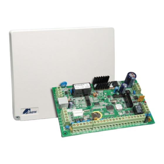
Overview Overview Overview Overview Overview Connection Diagrams Connection Diagrams Connection Diagrams Connection Diagrams Runner 8 Runner 8 Runner 8 Runner 8 The Runner 8 board can fit in 3 cases : PW-housing ,MINI-housing ,COMPACT housing . On the compact housing it equipped with transformer 20VA . On the Mini-housing and PW-housing it’s equipped with transformer 25VA . - Page 10 Runner 8 - PW8-16ST Runner Plus Runner Plus Runner Plus Runner Plus The Runner Plus board is fit into the Compact Box and it’s equipped with transformer 20VA. The Runner Plus can also be fed from an eternal adaptor 100-240V AC /14.4V DC ,1A. According to customer request.
- Page 11 Overview WCP PRO WCP PRO WCP PRO WCP PRO The WCP board is fitted into the WCP Housing and is equipped with a 15VA transformer. The WCP Pro can also be fed from an external adaptor 100-240V AC /14.4V DC ,1A. According to customer request.
-
Page 13: Input Options
Input Options Input Options Input Options Input Options Input Options Different Input Configurations Different Input Configurations Different Input Configurations Different Input Configurations The Runner 8 has nine separate programmable monitored analogue inputs, Programmable, multi-state detection inputs Programmable tamper input ( with optional Key-switch functions) NOTE NOTE NOTE... -
Page 14: Zone Wiring Examples
Runner 8 - PW8-16ST Zone Wiring Examples Zone Wiring Examples Zone Wiring Examples Zone Wiring Examples Type 0 (Short/Loop Circuit) Type 0 (Short/Loop Circuit) Type 0 (Short/Loop Circuit) Type 0 (Short/Loop Circuit) Type 1 Type 1- - - - 11 (Single EOL no Tamper) 11 (Single EOL no Tamper) Type 1 Type 1... - Page 15 Input Options 2k2 EOL, No Tamper 2k2 EOL, No Tamper 2k2 EOL, No Tamper 2k2 EOL, No Tamper Type 12 Configuration Type 12 Configuration Type 12 Configuration Type 12 Configuration Alarm & Tamper monitoring (contacts can be N/C or N/O). Type 15 Configuration Type 15 Configuration Type 15 Configuration...
-
Page 16: Other Inputs
Runner 8 - PW8-16ST Other Inputs Other Inputs Other Inputs Other Inputs Tamper Tamper Tamper Tamper A 24Hr tamper circuit is available for monitoring system tampers. This Tamper circuit is programmable as either normally closed loop or 2k2 EOL supervision (the default is usually a closed loop). -
Page 17: Outputs
Outputs Outputs Outputs Outputs Outputs Description of Outputs Description of Outputs Description of Outputs Description of Outputs 12 Volt Outputs 12 Volt Outputs 12 Volt Outputs 12 Volt Outputs There are three 12VDC outputs on the panel PCB. These 12 volt outputs are regulated and Thermal fuse protected against short circuits. -
Page 18: Expansion Port
Runner 8 - PW8-16ST Expansion Port Expansion Port Expansion Port Expansion Port The expansion port allows connection of the RS232 serial board, 90 second Voice Board, DTMF Board or EEPROM data transfer board (DTU). The serial board allows direct connection of a PC running the Upload/Download software. -
Page 19: Accessories
Accessories Accessories Accessories Accessories Accessories Radio Receiver Radio Receiver Radio Receiver Radio Receiver The panel can have wireless capability via the FW-RCVR receiver module. The receiver will add wireless capability to your system in the form or wireless PIR detectors, Wireless Radio- key transmitters and wireless reed switch transmitters. -
Page 20: Proximity Readers
Runner 8 - PW8-16ST you create an end of message marker. These markers are used to define the recording slots within the Voice Board and can be of varying length according to each message duration. To re-record your messages you must first press the "RESET" button on the speech module to get back to recording slot # 1. -
Page 21: Proximity Readers Connections
Accessories entering of a valid user code only, or on presentation of the tag/card followed by the user code (PIN). If the presented tag requires a PIN number to be entered, the LED on the reader will flash for 5 seconds after a valid tag to indicate that the PIN number should now be entered. -
Page 22: Night Monitor Keypad
Runner 8 - PW8-16ST Night Monitor Keypad Night Monitor Keypad Night Monitor Keypad Night Monitor Keypad The Night Monitor Keypad is designed to be a simple night arming station typically used in a bedroom situation. By pressing either of the <Night Monitor> buttons the alarm Stay Mode can be armed or disarmed. - Page 23 Accessories The Night Monitor keypad can be set to keypad addresses 5-8 by using Switches 1 & 2. Refer to chart below DIP Switch KP No: 5 KP No: 6 KP No: 7 KP No: 8 Switch 3 is unused on the PW8/16. It is used to force the armed LED to follow area A or B on other control panels.
-
Page 24: Keypad Indicators
Runner 8 - PW8-16ST Keypad Indicators Keypad Indicators Keypad Indicators Keypad Indicators LED Keyp LED Keyp LED Keyp LED Keypad Standard PW8/16LED Keypad Window Layout When the Panel is displaying codes and address values in program mode it may be necessary to display the 0 digit. - Page 25 Partition A Stay Mode Disarmed ARMED B Partition B Partition B Armed Partition B Stay Mode Disarmed ARMED C Spare ARMED D Spare PW8/16 LCD KEYPAD PW8/16 LCD KEYPAD PW8/16 LCD KEYPAD PW8/16 LCD KEYPAD CROW BIG LCD CROW SMALL LCD...
-
Page 26: Led Keypad
Runner 8 - PW8-16ST The table below gives details on the various LED indicators on the keypad and what they mean. LIGHT\INDICATION ON STEADY FLASHING " " " " READY Zone Unsealed All Zones Sealed TROUBLE Normal Trouble (Tamper) New Trouble (Tamper) Alarm Alarm Active... - Page 27 CABINET TAMPER Cabinet or Satellite Siren TROUBLE Flashing WRONG CODE ALARM Code Tamper at TROUBLE Flashing Keypad # LED’s 1-8 On Steady CROW KEYPAD TAMPER Keypad Tamper Alarm at TROUBLE On Steady SWITCH ACTIVATED Keypad # LED’s 1-8 On Steady...
- Page 28 Runner 8 - PW8-16ST LED KEYPAD VIEW MEMORY MODE cont HISTORICAL EVENT DISPLAY CHART-Continued EVENT DEVICE INDICATOR STATUS LOW BATTERY Controller Battery BATTERY Flashing MAINS FAILURE Controller Mains MAINS Flashing Supply 12V Output FAILURE (F2 or Controller on-board MAINS Flashing Thermal fuses LED 1 On Steady...
-
Page 29: Lcd Keypad
Keypad Indicators HISTORICAL EVENT DISPLAY CHART-Continued EVENT DEVICE INDICATOR STATUS ARMED Area "B" Armed "B" On Steady STAY MODE ON Area "A" in Stay Mode "A" Flashing STAY MODE ON Area "B" in Stay Mode "B" Flashing TELEPHONE LINE FAIL Panel Dialler LINE On Steady... - Page 30 Runner 8 - PW8-16ST HISTORICAL MEMORY EVENTS Following the “Current System Alarms” the panel will display the historical memory events. The panel stores the most recent events, (up to 255), including all alarm events, all system events such as mains failure etc as well as arm/disarm by User & Area. The memory events are displayed via the LCD keypad with the most recent event shown first and subsequent events following in descending order from newest to oldest.
-
Page 31: Keypad Address Assignment & Installation
"TOP", on the Arrowhead keypad base, or the screw should be at the bottom on the Crow keypad base. When fixing the base to the wall make sure the top of the screw heads will not touch or short out the underside of the PCB when the top half of the keypad is reinstalled. -
Page 32: Lcd Keypad
"TOP", on the Arrowhead keypad base, or the screw should be at the bottom on the Crow keypad base. When fixing the base to the wall make sure the top of the screw heads will not touch or short out the underside of the PCB when the top half of the keypad is reinstalled. -
Page 33: Adjusting Backlighting And Buzzer Tone
To enter “Local Program Mode” on the Arrowhead LCD Keypad you must press and hold the <CONTROL> button down and within 2 seconds, press the <BYPASS> button. To enter “Local Program Mode” on the Crow LCD Keypad you must press and hold the <CONTROL> button down and within 2 seconds, press the <ARM> button. - Page 34 By adjusting the frequency the volume of the tone produced at the buzzer varies as well. To increase the frequency of the CROW LCD buzzer Press “CONTROL” followed within 2 seconds by “A”. By holding down the “CONTROL” button and repeatedly pressing the “A”...
-
Page 35: Lcd Keypad "Local Edit" Mode
Accessing Local Edit Mode Accessing Local Edit Mode Accessing Local Edit Mode To enter Local Edit Program Mode on a CROW LCD Keypad Press “CONTROL” followed by “ARM” and hold for 2 seconds. N N N N OTE You must press the “Control” button first and the “Bypass” or “Arm” button must be pressed within 2 seconds of pressing the Control button. - Page 36 Runner 8 - PW8-16ST Local Edit Mode Direct Program Addresses Local Edit Mode Direct Program Addresses Local Edit Mode Direct Program Addresses Local Edit Mode Direct Program Addresses There are a number of program addresses available to you at this point. They are; [PROG]-[1]-[ENTER] to;...
- Page 37 LCD Keypad “Local Edit” Mode...
- Page 38 Runner 8 - PW8-16ST When you are at the desired main menu heading, press <ENTER> to access the data program location. See example below Changing the Area Single Character Changing the Area Single Character Identifier Identifier Changing the Area Single Character Changing the Area Single Character Identifier Identifier...
- Page 39 The letters <A..Z> indicate that the letters selected by the numeric buttons (0-9) will be in capitals. By pressing the “MEM# (CROW)” button once, the display will change to <a..z> indicating that the letters selected by the numeric buttons (0-9) will be lower case.
- Page 40 (Remember that there are a maximum of 16 characters per program address). If you make a mistake use the “STAY' (CROW)” button to move the cursor towards the left and make any corrections. When you are happy with the text Press “ENTER” to save the changes. You can program the text for all zones in the same way.
- Page 41 LCD Keypad “Local Edit” Mode You can now enter an Output name (maximum of 16 characters). When viewing events in “Memory” mode, the Output name will appear to identify what function the Output is controlling. When you are happy with the changes Press “ENTER” to save. Resetting Individual Text to Default or Resetting Individual Text to Default or Last Saved Setting Last Saved Setting...
-
Page 43: Program Mode Access
Program Mode Access Program Mode Access Program Mode Access Program Mode Access Program Mode Access Accessing Program Mode Accessing Program Mode Accessing Program Mode Accessing Program Mode How to Program Using Led Keypads How to Program Using Led Keypads How to Program Using Led Keypads How to Program Using Led Keypads The programming sequence follows this pattern;... -
Page 44: Exiting Program Mode
Runner 8 - PW8-16ST Note: Default Master User Code is code # 1 (P1E1E) which is 1234. You are now in Client Program Mode. Access to certain program locations is limited while in Client mode (see the options at address P5E). Each User can have different privileges based on the options assigned to the User at address P5E. - Page 45 Program Mode Access NOTE NOTE NOTE NOTE During programming Tampers and 24 hour alarms are disabled which allows quiet access to the panel, detectors and external siren units, etc. On exiting program mode, all inputs are scanned and if any tampers or 24Hr alarms are present an activation will occur..
- Page 46 Runner 8 - PW8-16ST Selecting the Main Selecting the Main Selecting the Main Selecting the Main- - - - Menu Headings Menu Headings Menu Headings Menu Headings (“ (“ (“ (“# # # # Up” Or “ Up” Or “ Up”...
- Page 47 Program Mode Access Stepping Back Through the Menus Stepping Back Through the Menus Stepping Back Through the Menus Stepping Back Through the Menus If you are in a Menu location, eg the “USER” Data Entry field, and you wish to step back one stage to the previous Sub-Menu, you need to press the <PROGRAM>...
- Page 48 Runner 8 - PW8-16ST LCD Keypad Program Menu Flowchart LCD Keypad Program Menu Flowchart LCD Keypad Program Menu Flowchart LCD Keypad Program Menu Flowchart...
- Page 49 Program Mode Access LCD “Main” Menu Headings LCD “Main” Menu Headings LCD “Main” Menu Headings LCD “Main” Menu Headings...
- Page 50 Runner 8 - PW8-16ST LCD Keypad Main & Sub Menu Program Chart LCD Keypad Main & Sub Menu Program Chart LCD Keypad Main & Sub Menu Program Chart LCD Keypad Main & Sub Menu Program Chart...
- Page 51 Program Mode Access...
- Page 52 Runner 8 - PW8-16ST...
-
Page 53: Special Keypad Functions
Special Keypad Functions Special Keypad Functions Special Keypad Functions Special Keypad Functions Special Keypad Functions Arming or Arming or Arming or Arming or Disarming Two Areas at a Keypad Disarming Two Areas at a Keypad Disarming Two Areas at a Keypad Disarming Two Areas at a Keypad If the panel is configured for two Areas “A&B”, and the option “ARM”... -
Page 54: Toggle Chime Mode On/Off
Toggle Chime Mode On/Off Toggle Chime Mode On/Off Toggle Chime Mode On/Off On the Crow LCD Keypad there is a “CHIME” button. Pressing and holding that button for two seconds will toggle Chime Mode from On-Off or Off-On. Send Manual Test Call... -
Page 55: Programming Users
Programming Users Programming Users Programming Users Programming Users Programming Users User Codes P1E 1-100E (NOTE: Users 21-100 can be Radio Users) Adding or changing a User Code Adding or changing a User Code Adding or changing a User Code Adding or changing a User Code Up to 100 codes can be programmed into the panel. -
Page 56: User Code Type
Runner 8 - PW8-16ST User Code Type User Code Type User Code Type User Code Type USER CODE TYPE - P2E 1-100E (NOTE: only Users 21-100 can be Radio Users) Option 0 - Keypad Code User {PIN} Option 1 - Radio user (User 21-100 only) Option 2 - Access Tag/Card User Option 3 - Both Code and Access Tag/Card User {Tag + PIN} Option 4 - Either Code or Access Tag/Card User {Tag or PIN}... - Page 57 Programming Users Option 1 Assigned to Area A Assigned to Area A Assigned to Area A Assigned to Area A - If a User has option 1 on, they can Arm/Disarm all zones assigned to Area A Option 2 Assigned to Area B Assigned to Area B - If a User has option 2 on, they can Arm/Disarm all zones Assigned to Area B Assigned to Area B...
-
Page 58: User Access Options
Runner 8 - PW8-16ST User Access Options User Access Options User Access Options User Access Options USER ACCESS OPTIONS - P4E 1-100E Option 1 - User can Arm Area Option 2 - User can Arm Stay Area Option 3 - User can Disarm Area Option 4 - User can Disarm Stay Area Option 5 - User is a Security Guard User Option 6 - User will Arm Latchkey Mode... -
Page 59: User Code Privileges
Radio User Type Radio User Type Radio User Type RADIO USER TYPE - P7E 21-100E (NOTE: only Users 21-100 can be Radio Users) Option 0 - Generic (General Pendant Type) Option 1 - Crow Freelink Pendant Option 21 - Ness Pendant... -
Page 60: Radio User Privileges
Generic type 0. Option 1 Crow Freelink Type Crow Freelink Type - If a Crow Freelink Radio Pendant is being used set the type to Crow Freelink Type Crow Freelink Type 1. When the pendant detects a battery low it will send a signal to the panel. -
Page 61: User To Keypad Assignment
Programming Users For example, if Time Zone #1 had a start time of 0800 and a stop time of 1700 and active days of 2-6 (Monday-Friday), a User with Time Zone 1 assigned can only be used between the hours of 0800-1700 from Monday to Friday. Outside these hours the User Code will not operate. -
Page 62: User To Output Mask
Runner 8 - PW8-16ST User to Output Mask User to Output Mask User to Output Mask User to Output Mask User to Output Mask - P12e 1-100e Option 1 - User is Mapped to Output # 1 Option 2 - User is Mapped to Output # 2 Option 3 - User is Mapped to Output # 3 Option 4 - User is Mapped to Output # 4 Option 5 - User is Mapped to Output # 5... -
Page 63: Radio Pendant Panic Alarm To Output
Programming Users Option 7 - User can turn OFF Output # 7 Option 8 - User can turn OFF Output # 8 Any user can be allowed to turn an Output OFF. This Function can be used to control external devices via the panel keypad with a User assigned to that Output. Once an Output is turned OFF by a User, the Output can be turned on by the same user or by a different user with the previous program location. - Page 64 Runner 8 - PW8-16ST If you wish to delete a single Radio Pendant, pressing P19E then the User number while in Program Mode will delete the stored code against that User, eg P19E 21E will remove the code stored for User 21. FIND a RADIO PENDANT LOCATION FIND a RADIO PENDANT LOCATION FIND a RADIO PENDANT LOCATION...
- Page 65 Programming Users LEARN ACCESS TAG/CARD CODES LEARN ACCESS TAG/CARD CODES LEARN ACCESS TAG/CARD CODES LEARN ACCESS TAG/CARD CODES LEARN ACCESS TAG/CARD CODES - P21E 1-100E An Access Tag/Card must be enrolled into the panel before it can be used. The panel can have up to 100 proximity tags (key-ring style card), or proximity cards loaded into the system.
-
Page 67: Miscellaneous Panel & Clock Settings
Miscellaneous Panel & Clock Settings Miscellaneous Pan Miscellaneous Pan Miscellaneous Pan Miscellaneous Panel & Clock el & Clock el & Clock el & Clock Settings Settings Settings Settings Installer Code Installer Code Installer Code Installer Code INSTALLER CODE - P25E 1E This code is used to enter full Installer Program mode (Program LED flashing on LED Keypad). -
Page 68: Two Trigger Timer
Runner 8 - PW8-16ST Two Trigger Timer Two Trigger Timer Two Trigger Timer Two Trigger Timer TWO TRIGGER TIMER - P25E 5E (0-255 Seconds) If a zone is set to two trigger, the zone has to cause an alarm twice within the two trigger time period to cause an alarm. -
Page 69: Miscellaneous Installer And Panel Options
Miscellaneous Panel & Clock Settings Miscellaneous Installer and Panel Options Miscellaneous Installer and Panel Options Miscellaneous Installer and Panel Options Miscellaneous Installer and Panel Options MISCELLANEOUS PANEL OPTIONS - P25E 10E Option 1 - Panel Tamper is 2k2 EOL Option 2 - Direct access to program mode for the Installer Code Option 3 - Disable Mains Fail Test Option 4 - Listen-in to O/P # 1 Low Volume Option 5 - Receiver Fail Lockout... - Page 70 Runner 8 - PW8-16ST turned on, the panel cannot be armed until the battery is either fully charged again, or it has been replaced (if faulty). Option 8 Installer Lockout Installer Lockout - Normally if the panel is powered up with the panel tamper open Installer Lockout Installer Lockout (ie system tamper alarm active) and in the Disarm state, then the panel will go into...
-
Page 71: Hide User Codes - User Options
Miscellaneous Panel & Clock Settings INSTALLER OPTIONS INSTALLER OPTIONS INSTALLER OPTIONS INSTALLER OPTIONS INSTALLER OPTIONS - P25E 11E Option 1 - Entry to Installer Mode Resets Confirmed Alarms Option 2 - Entry to Installer Mode Resets Tamper Alarms Option 3 - Entry to Installer Mode Resets Low Battery Alarm Option 4 - Entry to Installer Mode Resets Supervisory Alarms Option 5-7 - Spare Option 8 - User Codes Must be 4-6 digits long... -
Page 72: Daylight Saving (Dls) Settings
Runner 8 - PW8-16ST Setting Time Setting Time, Date and Daylight Saving , Date and Daylight Saving Setting Time Setting Time , Date and Daylight Saving , Date and Daylight Saving Setting Real Time Clock Setting Real Time Clock Setting Real Time Clock Setting Real Time Clock REAL TIME CLOCK HOUR/MINUTE - P26E 1E (Value 0-2359) -
Page 73: Outputs
Outputs Outputs Outputs Outputs Outputs NOTE: With all output programming options we refer to outputs 1-8. Only outputs 1-4 are available as standard, with outputs 5-8 requiring the connection of the optional 4 way output expander unit that connects to the keypad buss ( the output expander provides 4 change-over relay contacts). OUTPUT OPTIONS OUTPUT OPTIONS OUTPUT OPTIONS... - Page 74 Runner 8 - PW8-16ST turned on for the output/s concerned. To turn an output on locally at the keypad the operator simply presses the <Control> button for 2 seconds at which time the “Control” LED will illuminate on an LED keypad or the word “OUTPUTS” will appear on the LCD keypad to indicate that the Control mode is active.
- Page 75 Outputs Option 8 Pulsed Chime Mode Alarm Pulsed Chime Mode Alarm Pulsed Chime Mode Alarm Pulsed Chime Mode Alarm - Chime Zones programmed to this output will turn the output on for the duration of the Chime to Output time period (P41E). If this option is on the output will pulse at the pulse timer rate (P39E) for the duration of the chime zone to output timer (P41E).
- Page 76 Runner 8 - PW8-16ST Option 2 Pulse Pulse Pulse Pulse Output every 5 seconds when Disarmed Output every 5 seconds when Disarmed Output every 5 seconds when Disarmed Output every 5 seconds when Disarmed - This option will cause the Output to pulse every 5 seconds when the panel is disarmed.
-
Page 77: Output On Delay, Pulse, Reset And Chime Times
Outputs OUTPUT OPTIONS “D” OUTPUT OPTIONS “D” OUTPUT OPTIONS “D” OUTPUT OPTIONS “D” OUTPUT OPTIONS “D” - P37E 1-8E Option 1 - Siren Driver to Output (applies to O/P 1&2 only, requires an 8Ώ speaker) Option 2 - Output Reset Time is in Minutes Option 3 - Output “Silenced”... -
Page 78: Output Voice Board Remote Control Start Messages
Runner 8 - PW8-16ST The Pulse time affects the time the output turns on when the pulse timer is used on the Output. The pulse time is in 1/10th second increments so that very quick timing can be achieved. Functions like radio key Arm/Disarm Chirps to an Output or a flashing output (P34E option 2) all use the pulse timer. -
Page 79: Areas
Areas Areas Areas Areas Areas Area Arm and Special Fu Area Arm and Special Fu Area Arm and Special Fu Area Arm and Special Function Options nction Options nction Options nction Options Area Options “A” Area Options “A” Area Options “A” Area Options “A”... - Page 80 Runner 8 - PW8-16ST Area Options “B” Area Options “B” Area Options “B” Area Options “B” AREA OPTIONS “B” - P46E 1-2E (1 = Area A, 2 = Area B) Option 1 - Use Near and Verified Alarm reporting for All zones in this Area Option 2 - Area will Arm at the end of Time-Zone Option 3 - Area will Disarm at the end of Time-Zone Option 4 - Assign Chirps to Access tags...
-
Page 81: Area Arm/Stay Pulse & Chirps To Outputs
Areas Area Arm/Stay Pulse & Chirps to Outputs Area Arm/Stay Pulse & Chirps to Outputs Area Arm/Stay Pulse & Chirps to Outputs Area Arm/Stay Pulse & Chirps to Outputs Area Arm Indication to Output Area Arm Indication to Output Area Arm Indication to Output Area Arm Indication to Output AREA ARM INDICATION to OUTPUT - P47E 1-2E (1 = Area A, 2 = Area B) Option 1 - Output 1... - Page 82 Runner 8 - PW8-16ST Pendant Stay Mode Arm Chirp to Output Pendant Stay Mode Arm Chirp to Output Pendant Stay Mode Arm Chirp to Output Pendant Stay Mode Arm Chirp to Output PENDANT STAY MODE ARM CHIRP to OUTPUT - P51E 1-2E (1 = Area A, 2 = Area B) Option 1 - Output 1 Option 5 - Output 5 Option 2 - Output 2...
- Page 83 Areas Arm Pulse to Output Arm Pulse to Output Arm Pulse to Output Arm Pulse to Output ARM PULSE to OUTPUT - P54E 1-2E (1 = Area A, 2 = Area B) Option 1 - Output 1 Option 2 - Output 2 Option 3 - Output 3 Option 4 - Output 4 Option 5 - Output 5...
-
Page 84: Monitoring Account Code Number
Runner 8 - PW8-16ST disarmed, a single pulse will be applied to the output. The Pulse time (P39E) sets the length of the pulse. Armed Exit Delay Beeps to Keypad Armed Exit Delay Beeps to Keypad Armed Exit Delay Beeps to Keypad Armed Exit Delay Beeps to Keypad ARMED EXIT DELAY BEEPS TO KEYPAD - P58E 1-2E (1 = Area A, 2 = Area B) Option 1 - Keypad 1... - Page 85 Areas When the dialler is reporting to a monitoring station there must be a unique account code programmed to identify the panel. There is an account code for each area. The account code is 4 digits. Each digit can be a number from 0-9 as well as the special characters B,C,D,E & F.
-
Page 86: Remote Arm/Disarm Dtmf Code & Start Voice Message
Runner 8 - PW8-16ST Remote Arm/Disarm DTMF Code & Start Remote Arm/Disarm DTMF Code & Start Remote Arm/Disarm DTMF Code & Start Remote Arm/Disarm DTMF Code & Start Voice Message Voice Message Voice Message Voice Message DTMF Remote Control Code Number DTMF Remote Control Code Number DTMF Remote Control Code Number DTMF Remote Control Code Number... -
Page 87: Area Delinquency Delay
Areas Area Delinquency Delay Area Delinquency Delay Area Delinquency Delay Area Delinquency Delay AREA DELINQUENCY DELAY - P67E 1-2E (1 = Area A, 2 = Area B) (Value 0-99 Days) Each Area can have their own Delinquency time. The delinquency time monitors the arm/disarms of each Area. -
Page 88: Keypads
Chime Mode to be disabled with the <CHIME> button. If you press the <CHIME> button on a Crow LCD keypad for 2 seconds (and this option is turned on for that keypad) the display will show “Chime Mode OFF”. This means that the buzzer will now not sound at the keypad concerned and any Chime Mode Outputs will not activate. - Page 89 <1> & <3> are pressed simultaneously on the LED or keypad. It also enables the <CHIME> & <CONTROL> Panic Alarm when both buttons are pressing simultaneously on a Crow LCD keypad. Option 6 <4> & <6> Fire Alarm Enabled <4>...
-
Page 90: Keypad Arm , Stay , Aandb Button Options
Runner 8 - PW8-16ST Option 4 Telephone Line Fail Beeps Keypad Buz Telephone Line Fail Beeps Keypad Buz Telephone Line Fail Beeps Keypad Buz Telephone Line Fail Beeps Keypad Buzzer zer - If this option is on a Telephone Line Failure will cause the keypad buzzer to sound continuously. - Page 91 Keypads Option 8 - <ARM> button can Disarm Stay Mode During Exit Delay Option 1 <ARM> button can Arm - This option enables single button Arming using the <ARM> button. For single button operation to work options 1 & 3 must be off at location P45E.
- Page 92 Runner 8 - PW8-16ST Keypad <Stay> Button Area Options Keypad <Stay> Button Area Options Keypad <Stay> Button Area Options Keypad <Stay> Button Area Options KEYPAD <STAY> BUTTON AREA OPTIONS - P77E 1-8E Option 1 - <STAY> button can Arm Option 2 - <STAY> button can Arm Stay Mode Option 3 - <STAY>...
- Page 93 Keypad <A> Button Area Assignment Keypad <A> Button Area Assignment Keypad <A> Button Area Assignment KEYPAD <A> BUTTON AREA ASSIGNMENT - P78E 1-8E (APPLIES TO CROW LCD KEYPAD ONLY) Option 1 - Area “A” Option 2 - Area “B” Option 1 Area “A”...
- Page 94 Keypad <B> Button Area Options Keypad <B> Button Area Options Keypad <B> Button Area Options KEYPAD <B> BUTTON AREA OPTIONS - P81E 1-8E (APPLIES TO CROW LCD KEYPAD ONLY) Option 1 - <B> button can Arm Option 2 - <B> button can Arm A Mode Option 3 - <B>...
-
Page 95: Keypad To Output Mask
Keypads Option 4 <B> button can Disarm Stay Mode at All Times <B> button can Disarm Stay Mode at All Times <B> button can Disarm Stay Mode at All Times <B> button can Disarm Stay Mode at All Times - This option enables single button Disarming of Stay Mode using the <B>... -
Page 96: Keyboard Panic , Fire And Medical Alarms To Outputs And Kp Buzzer
Runner 8 - PW8-16ST Outputs via the <CONTROL> button you can avoid conflict with alarm outputs (eg the User can be denied access to outputs that are being used for alarm functions). Keyboard Panic, Keyboard Panic, Fire and Medical Alarms to Fire and Medical Alarms to Keyboard Panic, Keyboard Panic,... - Page 97 Keypads A Keypad generated Duress Alarm (see P25E2E) can be assigned to an Output or multiple Outputs. This can be used to operate an audible or visual alarm connected to the Output. A Duress alarm is created when the alarm is Disarmed with the Duress digit preceding a valid User Code.
-
Page 98: Keypad Chime Timer
Runner 8 - PW8-16ST Manua Manua Manua Manual Medical Alarm Beeps to Keypad l Medical Alarm Beeps to Keypad l Medical Alarm Beeps to Keypad l Medical Alarm Beeps to Keypad MANUAL MEDICAL ALARM BEEPS TO KEYPAD - P92E 1-8E Option 1 - Keypad 1 Option 5 - Keypad 5 Option 2 - Keypad 2... - Page 99 Keypads can be used to indicate Arm/Disarm state, Stay Mode Arm/disarm, output On/Off, etc. If chirps have been assigned to access tags/cards (P46E4E) and the output the reader LED is set to follow has the chirps assigned (P50E-P53E), then the output must have a minimum pulse time (P39E) of 10 for it to work correctly.
-
Page 100: Key-Switches
Runner 8 - PW8-16ST Key- - - - switches switches switches switches The two Key-Switch inputs are available on the panel tamper. Normally the panel tamper is a single 2k2 EOL resistor, however if the tamper input is wired as per the type 14 option shown on page 5, the 4k7 resistor becomes Key-switch number 1 and the 8k2 resistor becomes Key-switch number 2 (the 2k2 still acts as the tamper resistor). - Page 101 Key-switches Option 5 Key- - - - Switch has Security Guard Options Switch has Security Guard Options Switch has Security Guard Options - - - - If the key-switch has option 5 on, they can Switch has Security Guard Options Arm all Areas assigned, but they may only Disarm if the panel is currently Armed and in the alarm state.
-
Page 103: Zones
Zones Zones Zones Zones Zones Zone Area Assignment Zone Area Assignment Zone Area Assignment Zone Area Assignment ZONE AREA ASSIGNMENT - P121E 1-16E Option 1 - Area “A” Option 2 - Area “B” Option 1 Area “A” Area “A” Area “A” Area “A”... - Page 104 Runner 8 - PW8-16ST circuit in the sealed state. If this option is turned on it assumes that the alarm contact is N/O. Option 3 Spare Spare Spare Spare Option 4 Keypad Zone Keypad Zone - If this option is on the Zone will follow the Input at the Keypad Zone Keypad Zone corresponding Proximity Reader.
- Page 105 Zones Option 2 Zone is a Two Trigger Zone - If this option is on the zone will have to trigger twice within the two trigger time (P25E5E) before it will cause an alarm. If the zone does not trigger a second time before the two trigger time expires, the count is reset and it will take another two triggers to cause an alarm on this zone.
-
Page 106: One Eol
Runner 8 - PW8-16ST Option 1 - Can Arm if Zone is not Ready Option 2 - Will Send Multiple Reports to Dialler Option 3 - Zone is Monitored for Inactivity Option 4 - Zone is on Soak Test Option 5 - Zone will report to Area B Account Number Option 6 - Zone will Not Report 24 hour Alarms via Dialler Option 7 - Spare Option 8 - Spare... - Page 107 Zones doubling without tamper (Type 15). See chart on page 5 for the resistor combinations and colour codes. Zone EOL (End Zone EOL (End Zone EOL (End Zone EOL (End- - - - Of Of- - - - Line) Options Line) Options Line) Options - - - - P125e 1 Line) Options...
-
Page 108: Radio Zone Detector Type
Type 1 Crow Merlin PIR (unsupervised) Crow Merlin PIR (unsupervised) - - - - If a Crow Merlin radio PIR is used on the panel Crow Merlin PIR (unsupervised) Crow Merlin PIR (unsupervised) select Type 1 so the panel correctly recognizes the alarm, tamper & battery low signal from the device. - Page 109 Type 5 Crow AE Series Battery Low Crow AE Series Battery Low - If a Crow (AE) radio pendant or PIR is used on the Crow AE Series Battery Low Crow AE Series Battery Low panel selecting Type 5 allows the panel to correctly recognize the battery low and tamper signals from Crow (AE) devices.
-
Page 110: Zone Alarms To Output And Keyboard Buzzer Mapping
Runner 8 - PW8-16ST received from the detector. If no supervise signals are received from the PIR within the supervise timer value a supervised alarm is generated. Zone Alarms to Output and Keyboard Buzzer Zone Alarms to Output and Keyboard Buzzer Zone Alarms to Output and Keyboard Buzzer Zone Alarms to Output and Keyboard Buzzer Mapping... - Page 111 Zones Stay Mode Zone Alarms to Output Stay Mode Zone Alarms to Output Stay Mode Zone Alarms to Output Stay Mode Zone Alarms to Output STAY MODE ZONE ALARMS to OUTPUT - P129E 1-16E Option 1 - Output 1 Option 5 - Output 5 Option 2 - Output 2 Option 6 - Output 6 Option 3 - Output 3...
- Page 112 Runner 8 - PW8-16ST Armed Zone Alarm Beeps to Keypad Armed Zone Alarm Beeps to Keypad Armed Zone Alarm Beeps to Keypad Armed Zone Alarm Beeps to Keypad ARMED ZONE ALARM BEEPS TO KEYPAD - P134E 1-16E Option 1 - Keypad 1 Option 5 - Keypad 5 Option 2 - Keypad 2 Option 6 - Keypad 6...
- Page 113 Zones Zone Tamper Alarm Beeps to Keypad Zone Tamper Alarm Beeps to Keypad Zone Tamper Alarm Beeps to Keypad Zone Tamper Alarm Beeps to Keypad ZONE TAMPER ALARM BEEPS TO KEYPAD - P139E 1-16E Option 1 - Keypad 1 Option 5 - Keypad 5 Option 2 - Keypad 2 Option 6 - Keypad 6 Option 3 - Keypad 3...
-
Page 114: Zone Cid Report Codes
Runner 8 - PW8-16ST Option 2 - Keypad 2 Option 6 - Keypad 6 Option 3 - Keypad 3 Option 6 - Keypad 7 Option 4 - Keypad 4 Option 7 - Keypad 8 If Stay Mode is Armed and a Stay Mode delay zone triggers the entry delay it can also beep the keypad buzzer to warn that the entry delay is counting down and the alarm should be turned off. - Page 115 Zones alarm. There should be no reason to change this code but if some special application was to be used it can be changed at this location.
-
Page 116: Armed And Stay Mode Entry Delay Times
Runner 8 - PW8-16ST Zone Alarm Voice Message Number Zone Alarm Voice Message Number Zone Alarm Voice Message Number Zone Alarm Voice Message Number ZONE ALARM VOICE MESSAGE NUMBER - P160E 1-16E (Value 0-99) If the Optional Voice Board is fitted and the alarms are to be reported in Voice Format, each zone can be assigned a voice message to report the alarm type. -
Page 117: Learn/Find And Delete Radio Zone Codes
Zones Learn/Find and Delete Radio Zone Codes Learn/Find and Delete Radio Zone Codes Learn/Find and Delete Radio Zone Codes Learn/Find and Delete Radio Zone Codes Learn Radio Zone Codes Learn Radio Zone Codes Learn Radio Zone Codes Learn Radio Zone Codes LEARN RADIO ZONE CODES - P164E 1-16E A RADIO Zone must be enrolled into the panel before it can be used. -
Page 118: Time Zones
Runner 8 - PW8-16ST Time Zones Time Zones Time Zones Time Zones Holidays Holidays Holidays Holidays HOLIDAYS - P170E 1-8E (DDMMYY) It is possible to pre-program up to 8 holidays. Holidays can override the time-zone function on the programmed day. For example, if an output was automatically controlled by a time- zone, the pre-programmed holidays can stop the output from turning on or off on a holiday. -
Page 119: Time Zone Start And Stop Times
Time Zones Time Zone Start and Stop Times Time Zone Start and Stop Times Time Zone Start and Stop Times Time Zone Start and Stop Times Time Zone Start Time Time Zone Start Time Time Zone Start Time Time Zone Start Time TIMEZONE START TIME - P172E 1-8E (HHMM) The Time-zone start time is when the time-zone begins. -
Page 121: Dialler
Dialler Dialler Dialler Dialler Dialler Dialler Options Dialler Options Dialler Options Dialler Options DIALLER OPTIONS - P175E 1E Option 1 - Dialler is Enabled Option 2 - Fax Defeat Option 3 - Disable Telephone Line Monitoring Option 4 - Pulse Dialling (NOTE: For DTMF 4 & 5 must be OFF) Option 5 - Reverse Pulse Dialling (NOTE: For DTMF 4 &... - Page 122 Runner 8 - PW8-16ST Option 8 Force V21 Mode Force V21 Mode Force V21 Mode Force V21 Mode - The dial up panel to PC link can be established using either Bell 103 or V21. If the auto-detect function at option 7 does not result in the best format for your modem then you can force the panel to only communicate in one format.
- Page 123 Dialler Dialer Options 2 Dialer Options 2 Dialer Options 2 Dialer Options 2 DIALLER OPTIONS 2 - P175E 2E Option 1 - Step to next Number Option 2 - Upload/download uses Call-back Number Option 3 - Upload/download only if Disarmed Option 4 - Send Test Calls Only if Armed Option 5 - Spare Option 6 - Hold line open following Domestic/Voice report for DTMF control...
-
Page 124: Auto Answer Ring Count
Runner 8 - PW8-16ST Auto Answer Ring count Auto Answer Ring count Auto Answer Ring count Auto Answer Ring count AUTO-ANSWER RING COUNT - P175E 3E (Value 0-99) If the dialler is set to answer an in-coming call for remote control or upload/download the number of rings before answering the call can be set at this location. -
Page 125: Dialling Pre -Fix Number
Dialler Option 4 - Listen-in Enabled through the entire call only in Disarmed state Option 5 - Listen-in Enabled through the entire call only in Armed State Option 6 - Listen-in Enabled through the entire call only in Monitor Mode Option 7 - Listen-in Enabled when the panel answers a call Option 8 - Listen-in on at All Times The panel provides the facilities to use a speaker connected to Output # 1 to listen to the... - Page 126 Runner 8 - PW8-16ST The panel can be configured to allow remote operation of the Outputs via a remote telephone. The code programmed at this address is the DTMF code that must be used when performing this function. When dialling the panel and it has answered the call, after waiting for the panel modem tones to stop you can enter in the 4 digit DTMF code plus the Output number you wish to control, eg <1>...
-
Page 127: Miscellaneous Voice Reporting Message Numbers
Dialler MICROPHONE ON/OFF DTMF CODE NUMBER MICROPHONE ON/OFF DTMF CODE NUMBER MICROPHONE ON/OFF DTMF CODE NUMBER MICROPHONE ON/OFF DTMF CODE NUMBER MICROPHONE ON/OFF DTMF CODE NUMBER - P175E 13E (Value 1-4 digit code 0-9999) The panel can be configured to allow remote listen-in via an on-site microphone. The Voice Board must be fitted for the microphone feature to be available The code programmed at this address is the DTMF code that must be used when turning the microphone On or Off. - Page 128 Runner 8 - PW8-16ST BATTERY LOW ALARM VOICE MESSAGE NUMBER - P176E 6E (Value 0-99) BATTERY RESTORE VOICE MESSAGE NUMBER - P176E 7E (Value 0-99) TAMPER ALARMS VOICE MESSAGE NUMBER - P176E 8E (Value 0-99) DURESS ALARM VOICE MESSAGE NUMBER - P176E 9E (Value 0-99) LATCHKEY DISARM VOICE MESSAGE NUMBER - P176E 10E (Value 0-99)
-
Page 129: Telephone Numbers
Telephone Numbers Telephone Numbers Telephone Numbers Telephone Numbers Telephone Numbers Programming Telephone Numbers Programming Telephone Numbers Programming Telephone Numbers Programming Telephone Numbers Telephone Numbers Telephone Numbers Telephone Numbers Telephone Numbers TELEPHONE NUMBERS - P181E 1-8E (Value 1-16 digit number) The Telephone Numbers can be up to 16 digits long. They can also include some special functions or characters as per the chart below. - Page 130 Runner 8 - PW8-16ST Option 8 - 4 + 2 (Pulsed) 20 pps (2300 Hz Handshake, 1800 Hz transmit Tone) Option 9 - 4 + 2 DTMF (with Checksum) Option 1 Contact ID Contact ID Contact ID Contact ID - If this option is set for the telephone number, the panel will send a Contact ID message to a Monitoring Station.
-
Page 131: Telephone Number Report Options
Telephone Numbers TELEPHONE NUMBER REPORT OPTIONS TELEPHONE NUMBER REPORT OPTIONS TELEPHONE NUMBER REPORT OPTIONS TELEPHONE NUMBER REPORT OPTIONS TELEPHONE NUMBER REPORT OPTIONS - P183E 1-8E Option 1 - Stop Dialling if Kissed Off Option 2 - Monitor Call Progress Option 3 - Blind Dial Option 4 - Use Group Numbers for Contact ID Reporting Option 5 - Spare Option 6 - Auto Kiss-off for Voice/Domestic Reporting... -
Page 132: Maximum Dial Re Tries Per Telephone Number
Runner 8 - PW8-16ST Option 8 Used as the Call Used as the Call Used as the Call Used as the Call- - - - back Number back Number back Number back Number - - - - Any of the 8 telephone numbers can be designated as the Call-back number. -
Page 133: Dial Progress Options
Telephone Numbers Dial Progress Options Dial Progress Options Dial Progress Options Dial Progress Options Dialler Reporting Options “A” Dialler Reporting Options “A” Dialler Reporting Options “A” Dialler Reporting Options “A” DIALLER REPORTING OPTIONS “A” - P186E 1-8E Option 1 - Report Mains Fail Option 2 - Report Battery Low Option 3 - Report Radio Battery Low Option 4 - Report Line Fail... - Page 134 Runner 8 - PW8-16ST Option 2 Report Supervised Radio Alarm - If this option is on the panel will report a Supervised radio Alarm (see P25E4E). Option 3 Report Zone Inactivity Alarm - If this option is on the panel will report a Zone Inactivity (Sensor-watch) Alarm (see P163E).
- Page 135 Telephone Numbers Option 6 Report Access to Program Mode Report Access to Program Mode Report Access to Program Mode Report Access to Program Mode - If this option is on the panel will report a Contact ID code to indicate that either Client or Installer program Modes have been accessed.
-
Page 136: Call Divert Numbers & Options
Runner 8 - PW8-16ST Dialler Reporting Options “D” Dialler Reporting Options “D” Dialler Reporting Options “D” Dialler Reporting Options “D” DIALLER REPORTING OPTIONS “D” - P189E 1-8E Option 1 - Report Latchkey Disarm Option 2 - Report Delinquency Alarm Option 3 - Report Test Calls Option 4 - Report Fuse Failure Option 5 - Report Output 1 or 2 Fail Option 6 - Spare... -
Page 137: Call Divert Numbers & Options
Telephone Numbers Option 4 - Divert on Stay Mode Disarm Option 5 - Divert on Key-switch Arm/Disarm Option 6 - Divert on Time-zone Arm/Disarm Option 7 - Divert on DTMF or PC Arm/Disarm Option 8 - Divert on single button <ARM> or <STAY> Option 1 Divert Arm Divert Arm... - Page 138 Runner 8 - PW8-16ST Option 1 - Spare Option 2 - Spare Option 3 - Blind Dial Option 4 - Spare Option 5 - Spare Option 6 - Spare Option 7 - Use the Dial Pre-fix Number Option 8 - Spare Option 1 Spare Spare...
-
Page 139: 4+2 Program Options
4+2 Program Options 4+2 Program Options 4+2 Program Options 4+2 Program Options 4+2 Program Options When using the 4+2 Reporting Format the two digit report code can be changed if desired at the locations below. Also the two digit codes can include the numbers 0-9 as well the special characters B,C,D,E &... -
Page 140: Mains/Battery/Tamper/Duress & Arming 4+2 Codes
Runner 8 - PW8-16ST Mains/Battery/Tamper/Duress & Arming 4+2 Mains/Battery/Tamper/Duress & Arming 4+2 Mains/Battery/Tamper/Duress & Arming 4+2 Mains/Battery/Tamper/Duress & Arming 4+2 Codes Codes Codes Codes Mains Fail 4+2 Code ns Fail 4+2 Code ns Fail 4+2 Code ns Fail 4+2 Code MAINS FAIL 4+2 CODE - P195E 1E (Value 00-FF) Mains Fail Restore 4+2 Code Mains Fail Restore 4+2 Code... - Page 141 4+2 Program Options ARMED by KEY ARMED by KEY ARMED by KEY ARMED by KEY- - - - SWITCH 4+2 CODE SWITCH 4+2 CODE SWITCH 4+2 CODE SWITCH 4+2 CODE ARMED by KEY-SWITCH 4+2 CODE - P195E 14E (Value 00-FF) DISARMED by KEY DISARMED by KEY DISARMED by KEY...
-
Page 142: Diagnostic & Default Options
Runner 8 - PW8-16ST Diagnostic Diagnostic Diagnostic Diagnostic & Default Options & Default Options & Default Options & Default Options Display Software Version, Keypad Number Display Software Version, Keypad Number Display Software Version, Keypad Number Display Software Version, Keypad Number and Keypad Areas and Keypad Areas and Keypad Areas... -
Page 143: Read Or Write To The Dtu
Diagnostic & Default Options results of the walk-test will be saved in the memory event buffer and can be viewed by accessing memory display mode to verify which detectors were triggered during walk-test mode. If Output 1 or 2 are used for the Audible walk-test indication and a horn speaker is connected to the output (see P37E1 or 2E option 1), the siren on the output will give a single tone for the chirp instead of the swept tone used for alarms. -
Page 145: User Privileges Chart
User Privileges Chart User Privileges Chart User Privileges Chart User Privileges Chart User Privileges Chart P5E Options: Option 8: Can force download Option 7: Learn new radio devices Option 6: Change DTMF command Option 5: Change clock Option 4: Change phone numbers Option 3: Full access Option 2: Change others codes Program... -
Page 146: Telecom Interface
Runner 8 - PW8-16ST P5E Options: Option 8: Can force download Option 7: Learn new radio devices Option 6: Change DTMF command Option 5: Change clock Option 4: Change phone numbers Option 3: Full access Option 2: Change others codes Program Location Option 1: Change own code... - Page 147 User Privileges Chart Connection to the Telecom network should be made in accordance with Access Standards Newsletter #65 dated November 1993. This connection is to be readily accessible to allow disconnection in the event of a fault. An example of this connection method is shown below. NOTE NOTE NOTE...
-
Page 148: Contact Id Code Summary
Runner 8 - PW8-16ST Contact ID Code Summary Contact ID Code Summary Contact ID Code Summary Contact ID Code Summary In addition to the programmable Contact ID Event Code assignments defined at P157E, P158E, P159E, P175E (10E-12E), there are a number of fixed event codes. The programmable and fixed event codes are all listed in the table below. - Page 149 Contact ID Code Summary Event Type Event Extension Comment Code Delinquency Alarm System not Armed within # days Stay Mode Arm/Disarm (part Arm by “Stay” Button set) Stay Mode Arm/Disarm (part 001 to 100 Stay Mode Arm by User # 1- set) Stay Mode Arm/Disarm by Stay Mode Arm by Key-switch...
-
Page 150: Software Change Update Notice
Runner 8 - PW8-16ST Software change Update Software change Update Software change Update Software change Update Noti Noti Noti Notice There are currently no updates. -
Page 151: Pw8/16 Quick Start Guide
PW8/16 Quick Start Guide PW8/16 Quick Start Guide PW8/16 Quick Start Guide PW8/16 Quick Start Guide PW8/16 Quick Start Guide The default settings of this panel have been chosen to allow the system to be up and running with a minimum of programming. Because of this there are normally only a handful of program addresses that need to be changed to get the system fully functional. -
Page 152: Pw8/16 Configuration Summary Guide
Runner 8 - PW8-16ST PW8/16 CONFIGURATION PW8/16 CONFIGURATION PW8/16 CONFIGURATION PW8/16 CONFIGURATION SUMMARY GUIDE SUMMARY GUIDE SUMMARY GUIDE SUMMARY GUIDE The following program summary is an abbreviated version of all the panel program addresses. This is intended as a quick guide to finding a program address. In many address locations, there is a main address (e.g. -
Page 153: Users
Users Users Users Users הסימניה אינה מוגדרת שגיאה PROGRAMMING USERS ............ הסימניה אינה מוגדרת שגיאה .................. ODES הסימניה אינה מוגדרת שגיאה ................הסימניה אינה מוגדרת שגיאה .................. REAS הסימניה אינה מוגדרת שגיאה ..............CCESS PTIONS יה אינה מוגדרת הסימנ שגיאה .............. - Page 154 Radio User Type 21-100E Radio User 21-100 Type 0 = General Pendant Type (Default = 0) 1 = Crow Freelink Pendant 21 = Ness Pendant Radio User Privileges 21-100E Radio Users 21-100 Privileges 1 = Pendant Can Disarm at All Times...
- Page 155 PW8/16 CONFIGURATION SUMMARY GUIDE User to Keypad Assignment P10E 1-100E User # 1-100 Keypad Assignment 1 = Can Operate at Keypad # 1 (Default = All On) 2 = Can Operate at Keypad # 2 3 = Can Operate at Keypad # 3 4 = Can Operate at Keypad # 4 5 = Can Operate at Keypad # 5 6 = Can Operate at Keypad # 6...
- Page 156 Runner 8 - PW8-16ST User Can Turn an Output OFF P14E 1-100E User # 1-100 Can Turn Off an Output 1 = User Can Turn off Output # 1 (Default = All Off) 2 = User Can Turn off Output # 2 3 = User Can Turn off Output # 3 4 = User Can Turn off Output # 4 5 = User Can Turn off Output # 5...
-
Page 157: Miscellaneous Panel & Clock Settings
PW8/16 CONFIGURATION SUMMARY GUIDE Miscellaneous Panel & Clock Settings Miscellaneous Panel & Clock Sett ings Miscellaneous Panel & Clock Sett Miscellaneous Panel & Clock Sett ings ings הסימניה אינה מוגדרת שגיאה MISCELLANEOUS PANEL & CLOCK SETTINGS ....הסימניה אינה מוגדרת שגיאה... -
Page 158: User Options
Runner 8 - PW8-16ST Miscellaneous Panel Options P25E Misc. Panel Options Miscellaneous Options (Default = 1,2) 1 = Panel Tamper is 2k2 EOL 2 = Direct access to program mode for the installer code. 3 = Disable Mains Fail Test 4 = Listen-in to O/P # 1 Low Volume 5 = Receiver Fail Lockout 6 = Send output information to keypad bus... -
Page 159: Outputs
PW8/16 CONFIGURATION SUMMARY GUIDE Outputs Outputs Outputs Outputs הסימניה אינה מוגדרת שגיאה OUTPUTS................הסימניה אינה מוגדרת שגיאה OUTPUT OPTIONS ............... הסימניה אינה מוגדרת שגיאה ......UTPUT ELAY ULSE ESET AND HIME IMES הסימניה אינה מוגדרת שגיאה ...... UTPUT OICE OARD EMOTE ONTROL TART... -
Page 160: Areas
Runner 8 - PW8-16ST Programming Output Options “D” P37E 1-8E Options “D” for Outputs 1-8 1 = Siren Driver to Output (requires a horn speaker, outputs 1&2) (Default = All Off) 2 = Output reset timer is minutes (clear for seconds) 3 = Output ‘silenced’... - Page 161 PW8/16 CONFIGURATION SUMMARY GUIDE Area “A” & “B” Options A P45E 1-2E Area A&B Options A 1 = Arm Button Required Before Code to Set (1=Area “A”) (Default = All Off) 2 = Stay Button Required Before Code to Set Stay Mode (2=Area “B”) 3 = Code required to Set 4 = Code Required to Bypass Zones 5 = Spare...
- Page 162 Runner 8 - PW8-16ST Area “A” & “B” Pendant (or Access Tag) Disarm Chirp to Output P52E 1-2E Area A&B Disarm Chirp to Output - Value 1-8 (for Outputs 1-8) (Two chirps to the output for disarm) (1=Area “A”) (Default = All Off) (2=Area “B”) Area “A”...
- Page 163 PW8/16 CONFIGURATION SUMMARY GUIDE Area “A” & “B” Monitoring Account Code Number P62E 1-2E Area A&B Account Code - Value 0000-FFFF (1=Area “A”) (Default = 0000 for Areas A&B) (2=Area “B”) Area “A” & “B” Remote “Command Control” Code Number P63E 1-2E Area A&B Command Control code -...
-
Page 164: Keypads
Runner 8 - PW8-16ST Keypads Keypads Keypads Keypads הסימניה אינה מוגדרת שגיאה KEYPADS................מניה אינה מוגדרת הסי שגיאה ..............EYPAD SSIGNMENT הסימניה אינה מוגדרת שגיאה LED C ....EYPAD UTTON PERATIONS EEPS AND ONTROL הסימניה אינה מוגדרת שגיאה ........EYPAD UTTON PTIONS הסימניה... - Page 165 PW8/16 CONFIGURATION SUMMARY GUIDE Keypad “ARM” Button Area Assignment P74E 1-8E Keypad “ARM” Button Area (Default = 1) 1 = “ARM” Button assigned to Area “A” 2 = “ARM” Button assigned to Area “B” Keypad “ARM” Button Area Options P75E 1-8E Keypad “ARM”...
- Page 166 Runner 8 - PW8-16ST Keypad “B” Button (Large LCD KP only) Area Assignment P80E 1-8E Keypad “B” Button Area 1 = “B” Button assigned to Area “A” (Default = 2) 2 = “B” Button assigned to Area “B” Keypad “B” Button (Large LCD KP only) Area Options P81E 1-8E Keypad “B”...
- Page 167 PW8/16 CONFIGURATION SUMMARY GUIDE “Fire (4&6)” Alarm to Outputs P85E 1-8E Keypad “Fire (4&6)” Alarm to Outputs (Default = 1,2) 1 = The Keypad “Fire (4&6)” Alarm will turn on Output # 1 2 = The Keypad “Fire (4&6)” Alarm will turn on Output # 2 3 = The Keypad “Fire (4&6)”...
- Page 168 Runner 8 - PW8-16ST Keypad “Wrong Code” Alarm to Outputs P89E 1-8E Keypad “Wrong Code” Alarm to Outputs (Default = 1,2) 1 = The Keypad “Wrong Code” Alarm will turn on Output # 1 2 = The Keypad “Wrong Code” Alarm will turn on Output # 2 3 = The Keypad “Wrong Code”...
- Page 169 PW8/16 CONFIGURATION SUMMARY GUIDE Wrong Code or Keypad Tamper Switch Alarm Beeps to Keypads P93E 1-8E Wrong Code or Keypad Tamper Switch Alarm Beeps to Keypads (Default = All On) 1 = A Wrong Code or KP Tamper Alarm at Keypad 1-8 will Beep KP # 1 2 = A Wrong Code or KP Tamper Alarm at Keypad 1-8 will Beep KP # 2 3 = A Wrong Code or KP Tamper Alarm at Keypad 1-8 will Beep KP # 3 4 = A Wrong Code or KP Tamper Alarm at Keypad 1-8 will Beep KP # 4...
-
Page 170: Key Switches
Runner 8 - PW8-16ST Key- - - - Switches Switches Switches Switches הסימניה אינה מוגדרת שגיאה KEY-SWITCHES..............דרת הסימניה אינה מוג שגיאה ............WITCH SSIGNMENT הסימניה אינה מוגדרת שגיאה ............ WITCH ISARM PTIONS Key-switch Area Assignment P111E 1-2E K/S 1 & 2 assigned to Areas A or B - 1 = Assigned to Area “A”... - Page 171 PW8/16 CONFIGURATION SUMMARY GUIDE Programming Zone Options A P122E 1-16E Programming Zone Options A 1 = Zone is Active (Default Zone 1-4 = 1,6,7,8) 2 = Zone is N/O (Off = N/C) (Default Zone 5-8 = 1,7,8) 3 = Spare (Default Zone 9-16 = 7,8) 4 = Keypad Zone 5 = Zone is a Radio Zone...
- Page 172 P127E 1-16E Programming the Radio Zone Type from the List - Value = 1-35 (Default = 3) 0 = Generic 1 = Crow Merlin PIR (supervised signal ignored) 2 = Crow Merlin PIR (supervised signal active) 3 = Freelink with checksum (supervised signal active)
- Page 173 PW8/16 CONFIGURATION SUMMARY GUIDE Armed Stay Mode Zone Alarms to Outputs P129E 1-16E Armed Stay Mode Zone Alarms to Output (Default = 2) 1 = A Stay Mode Zone Alarm will Turn On Output # 1 2 = A Stay Mode Zone Alarm will Turn On Output # 2 3 = A Stay Mode Zone Alarm will Turn On Output # 3 4 = A Stay Mode Zone Alarm will Turn On Output # 4 5 = A Stay Mode Zone Alarm will Turn On Output # 5...
- Page 174 Runner 8 - PW8-16ST Armed Zone Alarm Beeps to Keypads P134E 1-16E Armed Zone Alarm Beeps to Keypads (Default = 1,2,3,4,5,6,7,8) 1 = An Armed Zone Alarm will Beep Keypad #1 2 = An Armed Zone Alarm will Beep Keypad #2 3 = An Armed Zone Alarm will Beep Keypad #3 4 = An Armed Zone Alarm will Beep Keypad #4 5 = An Armed Zone Alarm will Beep Keypad #5...
- Page 175 PW8/16 CONFIGURATION SUMMARY GUIDE Zone Tamper Alarm Beeps to Keypads P139E 1-16E Zone Tamper Alarm Beeps to Keypads (Default = 1,2,3,4,5,6,7,8) 1 = A Zone Tamper Alarm will Beep Keypad #1 2 = A Zone Tamper Alarm will Beep Keypad #2 3 = A Zone Tamper Alarm will Beep Keypad #3 4 = A Zone Tamper Alarm will Beep Keypad #4 5 = A Zone Tamper Alarm will Beep Keypad #5...
- Page 176 Runner 8 - PW8-16ST Stay Mode Entry Delay Beeps to Keypads P143E 1-16E Stay Mode Entry Delay Beeps to Keypads (Default = 1,2,3,4,5,6,7,8) 1 = Stay Mode Entry Delay will Beep Keypad #1 2 = Stay Mode Entry Delay will Beep Keypad #2 3 = Stay Mode Entry Delay will Beep Keypad #3 4 = Stay Mode Entry Delay will Beep Keypad #4 5 = Stay Mode Entry Delay will Beep Keypad #5...
- Page 177 PW8/16 CONFIGURATION SUMMARY GUIDE Alarm CID Reporting Codes Alarm CID Reporting Codes Alarm CID Reporting Codes Alarm CID Reporting Codes Zone Alarm Contact ID Reporting Codes P157E 1-16E Zone Alarm Contact ID Reporting Code - (Default = 130) Zone Near Alarm Contact ID Reporting Codes P158E 1-16E Zone Near Alarm Contact ID Reporting Code - (Default = 138) Zone Intrusion Verified Alarm Contact ID Reporting Codes...
-
Page 178: Time Zones
Runner 8 - PW8-16ST Radio Codes Radio Codes Radio Codes Radio Codes Enrolling Radio Zone Codes P164E 1-16E Learn Radio Zone Codes Delete a Specific Radio Zone Code P165E 1-16E Delete a Specific Radio Zone Code Find Radio Zone Memory Location P166E 0E This will find the zone # of any Radio Zone code stored in the panel Only press 0E when using LED Keypad. -
Page 179: Dialler
PW8/16 CONFIGURATION SUMMARY GUIDE Dialler Dialler Dialler Dialler הסימניה אינה מוגדרת שגיאה DIALLER................הסימניה אינה מוגדרת שגיאה ................IALLER PTIONS הסימניה אינה מוגדרת שגיאה ............... NSWER ING COUNT גדרת הסימניה אינה מו שגיאה ................. ALL OPTIONS הסימניה אינה מוגדרת שגיאה .......... - Page 180 Runner 8 - PW8-16ST Keypad Listen-in Options P175E 6E Keypad Listen-in Options (Default = 1,2,3,4,5,6,7) 1 = Enabled During Dialling in Disarm State only 2 = Enabled During Dialling in Armed State only 3 = Enabled During Dialling in Stay Mode State only 4 = Enabled Throughout the call in Disarm State only 5 = Enabled Throughout the call in Armed State only 6 = Enabled Throughout the call in Stay Mode State only...
-
Page 181: Telephone Numbers
PW8/16 CONFIGURATION SUMMARY GUIDE Programming Voice Board Messages P176E 1E Keypad or Radio “Panic” Alarm Voice Message Number - Value 0-99 (Default = 1) P176E 2E “Fire” Alarm Voice Message Number - Value 0-99 (Default = 1) P176E 3E “Medical” Alarm Voice Message Number - Value 0-99 (Default = 1) P176E 4E “Mains Failure”... - Page 182 Runner 8 - PW8-16ST Telephone Number Reporting Options P183E 1-8E Telephone Number Reporting Options (Default = 1,2) 1 = Stop Dialling if Kissed off 2 = Monitor Call Progress 3 = Blind Dial 4 = Use Group Numbers for Contact ID Reporting 5 = Spare 6 = Auto Kiss-off for Voice/Domestic Reporting 7 = Use the Dialling Pre-fix...
- Page 183 PW8/16 CONFIGURATION SUMMARY GUIDE Dialler Reporting Options D P189E 1-8E Dialler Options D 1 = Report Latchkey Disarm (Default = 3,4) 2 = Report Delinquent 3 = Report Tests 4 = Report Fuse Failure 5 = Report Output 1 or 2 Fail 6 = Spare 7 = Spare Spare...
-
Page 184: Miscellaneous 4+2 Program Options
Runner 8 - PW8-16ST Miscellaneous 4+2 Program Options Miscellaneous 4+ 2 Program Options Miscellaneous 4+ Miscellaneous 4+ 2 Program Options 2 Program Options הסימניה אינה מוגדרת שגיאה 4+2 PROGRAM OPTIONS..........הסימניה אינה מוגדרת שגיאה 4+2 C ..............SING THE ODES הסימניה... - Page 185 PW8/16 CONFIGURATION SUMMARY GUIDE Keypad “Fire” Alarm 4+2 Reporting Code P195E 19E Keypad Fire Alarm 4+2 Code - Two digit value from 00-FF Keypad “Fire” Alarm 4+2 Restore Reporting Code P195E 20E Keypad Fire Alarm Restore 4+2 Code - Two digit value from 00-FF Keypad “Medical”...
-
Page 186: Panel Diagnostic & Default Options
Runner 8 - PW8-16ST Panel Diagnostic & Default Options Panel Diagnostic & Default Options Panel Diagnostic & Default Options Panel Diagnostic & Default Options הסימניה אינה מוגדרת שגיאה DIAGNOSTIC & DEFAULT OPTIONS........הסימניה אינה מוגדרת שגיאה .... ISPLAY OFTWARE ERSION EYPAD UMBER AND EYPAD... -
Page 187: Crow Electronic Engineering Ltd. (Crow) Warranty Policy Certificate
In no case shall Crow be liable to anyone for any consequential or incidental damages (inclusive of loss of profit, and whether occasioned by negligence of the Crow or any third party on its behalf) for breach of this or any other warranty, expressed or implied, or upon any other basis of liability whatsoever. -
Page 188: How To Contact Us
ITALY: LATIN AMERICA: LATIN AMERICA: LATIN AMERICA: LATIN AMERICA: POLAND: POLAND: POLAND: POLAND: CROW LATIN AMERICA VIDICON SP. ZO. O. DEATRONIC 5753 NW 151 .Street 15 Povazkowska St. VIA Giulianello 4/14 MIAMI LAKES, 01 – 797 Warsaw 00178 ROMA, ITALY FL 33014 –...
Need help?
Do you have a question about the runner series and is the answer not in the manual?
Questions and answers