Table of Contents
Advertisement
Quick Links
1
SERVICE MANUAL
Level 1&2
RM-412/RM-413
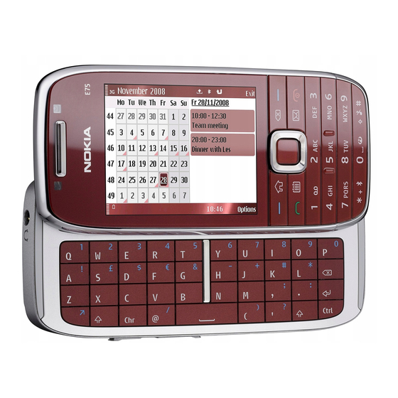
Transceiver characteristics
Band:
GSM/EDGE 850/900/1800/1900
RM-412: WCDMA 2100 (band I)/1900 (band II)/900
(Band VIII)
RM-413: WCDMA 2100 (band I)/1900 (band II)/850
(Band V)
Display:
2,4" QVGA (320x240), 16M colours, Active area 36.72 x
48.96 mm
Keypad:
Full QWERTY keyboard
Camera:
Main camera: 3,2 Mpix, Flash, Auto-focus
Secondary camera; VGA
Operating System:
Symbian OS 9.3/S60 3.2 release 3
Connections:
2 mm charger, 3,5 mm AV connector, Bluetooth 2.0 EDR,
USB 2.0 (Micro USB), A-GPS, WLAN 802.11g
Transceiver with BL-4U battery pack
Talk time
GSM:
Up to 5 hours
WCDMA:
Up to 4 hours
Confidential Copyright © 2009 NOKIA All rights reserved
Nokia E75 RM-412/RM-413
Service Manual Level 1&2
Standby
Note
GSM:
Talk times are
Up to 12 days
dependant on
WCDMA:
network
Up to 11days
parameters and
phone settings
Version 1.0
ISSUE 1
Advertisement
Table of Contents

Related Manuals for Nokia E75


Summary of Contents for Nokia E75
- Page 1 Talk times are Up to 5 hours Up to 12 days dependant on WCDMA: WCDMA: network Up to 4 hours Up to 11days parameters and phone settings Confidential Copyright © 2009 NOKIA All rights reserved Version 1.0 ISSUE 1...
-
Page 2: Table Of Contents
Exploded view ....................................9 8. Service devices ....................................10 9. SW-update ..................................... 11 10. Disassembly instruction ............................... 12 11. Assembly hints..................................17 12. Solder components ................................20 Confidential Copyright © 2009 NOKIA All rights reserved Version 1.0 ISSUE 1... -
Page 3: Change History
3.2.2009 Approved version The purpose of this document is to help NOKIA service levels 1 and 2 workshop technicians to carry out service to NOKIA products. This Service Manual is to be used only by authorized NOKIA service suppliers, and the content of it is confidential. Please note that NOKIA provides also other guidance documents (e.g. -
Page 4: Copyright
Nokia operates a policy of continuous development. Nokia reserves the right to make changes and improvements to any of the products described in this document without prior notice. Under no circumstances shall Nokia be responsible for any loss of data or income or any special, incidental, consequential or indirect damages howsoever caused. -
Page 5: Warnings And Cautions
3. Use only approved components as specified in the parts list. 4. Ensure all components, modules screws and insulators are correctly re–fitted after servicing and alignment. 5. Ensure all cables and wires are repositioned correctly Confidential Copyright © 2009 NOKIA All rights reserved Version 1.0 ISSUE 1... -
Page 6: Esd Protection
Nokia E75 RM-412/RM-413 Service Manual Level 1&2 4. ESD PROTECTION Nokia requires that service points have sufficient ESD protection (against static electricity) when servicing the phone. Any product of which the covers are removed must be handled with ESD protection. -
Page 7: Care And Maintenance
All of the above suggestions apply equally to the product, battery, charger or any accessory. Confidential Copyright © 2009 NOKIA All rights reserved Version 1.0 ISSUE 1... -
Page 8: Battery Information
Batteries’ performance is particularly limited in temperatures well below freezing. Do not dispose batteries in a fire! Dispose of batteries according to local regulations (e.g. recycling). Do not dispose as household waste. Confidential Copyright © 2009 NOKIA All rights reserved Version 1.0 ISSUE 1... -
Page 9: Exploded View
TYPE LABEL I0212 I0205 USB/SD-DOOR BATTERY COVER ASSY I0217 I0219 SCREW 1.4X3.4 I0218 Only available as These parts can not be Ver. 1.0 assembly reused after removal Confidential Copyright © 2009 NOKIA All rights reserved Version 1.0 ISSUE 1... -
Page 10: Service Devices
Online. Supplier or manufacturer contacts for tool re-order can be found in “Recommended service equipment” document on NOKIA Online. BL-4U Battery SS-198 UI flex assembly jig Confidential Copyright © 2009 NOKIA All rights reserved Version 1.0 ISSUE 1... -
Page 11: Sw-Update
To use the FLS-5 Flash Dongle, follow the user guide inside the sales package. Please check always for the latest version of flash software, wich is available on Nokia Online. Confidential Copyright © 2009 NOKIA All rights reserved Version 1.0... -
Page 12: Disassembly Instruction
Service Manual Level 1&2 10. DISASSEMBLY INSTRUCTION 1) Nokia E75 disassembly. 2) You must use the Nokia Standard Toolkit version 2. 3) To remove the BATTERY COVER ASSY, push the 4) Slide the phone open. Then unscrew these four button on the bottom side and then lift up the Torx+ 4 screws in the order shown. - Page 13 12) Slide the phone open and release the five clips shown. holding the QWERTY KEYMAT using the SRT-6. Release the clip near the space bar first. Confidential Copyright © 2009 NOKIA All rights reserved Version 1.0 ISSUE 1...
- Page 14 4 screw. the two remaining screws become visible. 17) Open the AV connector with the SRT-6. 18) Open the Camera connector with the SRT-6. Confidential Copyright © 2009 NOKIA All rights reserved Version 1.0 ISSUE 1...
- Page 15 24) Open the DYNAMIC FLEX connector with the SRT-6 opening a small clip with the dental tool. and separate the engine board and the SLIDE MODULE. Be careful not to damage the connector. Confidential Copyright © 2009 NOKIA All rights reserved Version 1.0 ISSUE 1...
- Page 16 ASSEMBLY, do not use it again. 29) Start releasing the QWERTY DOMESHEET with the 30) Carefully remove the QWERTY DOMESHEET. Make dental tool. sure that the whole QWERTY DOMESHEET is removed. Confidential Copyright © 2009 NOKIA All rights reserved Version 1.0 ISSUE 1...
-
Page 17: Assembly Hints
SS-93 to remove it. 29) Finally use the dental tool to release the IHF -END OF DISASSEMBLY- SPEAKER and the IHF SPEAKER gasket. 11. ASSEMBLY HINTS Confidential Copyright © 2009 NOKIA All rights reserved Version 1.0 ISSUE 1... - Page 18 DYNAMIC FLEX. 5) Tighten the screw to the torque of 16 Ncm. 6) Tighten the screws to the torque of 16 Ncm in the order shown. Confidential Copyright © 2009 NOKIA All rights reserved Version 1.0 ISSUE 1...
- Page 19 10) Tighten the screws to the torque of 20 Ncm in the marked areas to activate the adhesive on the order shown. WINDOW ASSY. Maintain the pressure for 5 seconds. Confidential Copyright © 2009 NOKIA All rights reserved Version 1.0 ISSUE 1...
-
Page 20: Solder Components
Nokia E75 RM-412/RM-413 Service Manual Level 1&2 12. SOLDER COMPONENTS Solder components only for Level 2 X1000 V2426 X1451 X1001 G2200 X2700 X7591 F3300 Confidential Copyright © 2009 NOKIA All rights reserved Version 1.0 ISSUE 1...
Need help?
Do you have a question about the E75 and is the answer not in the manual?
Questions and answers