Table of Contents
Advertisement
Quick Links
Advertisement
Table of Contents

Related Manuals for CiA PROTEC4

Summary of Contents for CiA PROTEC4
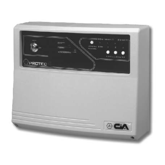
- Page 1 PROTEC4 4 zones burglary central unit USER’S MANUAL...
-
Page 2: Table Of Contents
PROTEC4 - User’s manual Index Introduction Chapter 1 1.1 Central unit description ....................19 1.2 Operating features ......................19 1.3 Technical features......................20 Installation Chapter 2 2.1 General instructions......................21 2.2 Power supply ........................21 2.3 Connections........................22 2.3.1 Electronic key.....................23 2.3.2 Reed contacts and volumetric detectors ............24 2.3.3... -
Page 3: Chapter 1 Introduction
Introduction Dear customer, we desire thank you for buying a CIA product. We recommend us to read this manual with attention, because it will be very useful in phase of installation and use. As CIA customer you can make use of a series of services, such as the technical telephone assistance on the CIA products. -
Page 4: Technical Features
PROTEC4 - User’s manual Technical features Operating voltage: 230V~ ±10% 50Hz Maximum current absorption: 140mA Service output voltage: 13V! ±5% Maximum current supplied on services output: 650mA Fuse on services output voltage F type 1A Maximum current supplied on sirens output... -
Page 5: Chapter 2 Installation
Installation Installation General instructions Do not install the device at places exposed to the bad weather or to the extreme temperatures. The central unit is protected from the opening, but the installation in a safe place is a greater protection of the device. For a strong and safe fixing, it needs making sure the wall surface is plane. -
Page 6: Connections
The PROTEC4 and the AL5 don’t need the ground connection, but for safety reasons and for the respect of the laws in vigor we suggest to make and test a ground connection for the all devices that need it. -
Page 7: Electronic Key
Installation 2.3.1 Electronic key Remove the arch In series to the 24h line ATTENTION! Optional connection* SK100 * This connection will activate the 24h anti-sabotage protection alarm when a false key is inserted in the SKI connector. -
Page 8: Reed Contacts And Volumetric Detectors
Long wires PG12 ATTENTION! The PROTEC4 doesn’t allow the connection of the ‘switch’ contacts for rolling shutters type C778 directly on the terminal boards becouse this central unit hasn’t got an impulse counter. Use the SCHSW impulse counter board to connect the ‘switch’ contact for rolling shutters type C778, or use the ‘switch’... -
Page 9: Telephone Dialer
Installation 2.3.3 Telephone dialer In series to the 24h line TD81 Phone line... -
Page 10: Sirens
PROTEC4 - User’s manual 2.3.4 Sirens In series to the 24h line SA310 SP31... -
Page 11: Chapter 3 Programming
Programmation Programmation Exiting time regulation The exiting time allows the system user to leave the protected zones after the system enabling. During this time a possible activation of the sensors of the all protection zones doesn’t activate alarms. This timing is adjustable from 5 to 75 seconds by the trimmer situated inside of the central unit (see picture below). -
Page 12: Chapter 4 Operating
PROTEC4 - User’s manual Operating Front panel description Key switch released zone status visualization On system disabled, by pressing this button, the Allows to enable / disable the system. If there's blinking zones status control LEDs an electronic key or another command system , indicate the ALARM MEMORY (i.e. -
Page 13: System Enabling
Operating System enabling 4.2.1 Enabling by the front panel key switch Verify that the zone status LEDs and are turned off. If they’re switched on it’s necessary to close the doors and windows relative to the zone signalled opened. It’s also possible that the zone signalled opened could be the one relative to the volumetric detectors;... -
Page 14: System Disabling
PROTEC4 - User’s manual System disabling 4.3.1 Disabling by the front panel key switch Open the entering door. The yellow LED “ALLARME” starts blinking. The alarm will not activates immediately becouse the entering door is usually protected by the delayed zone 1: the entering time will allows to reach the central unit to disable the system. -
Page 15: Zones Exclusion
Operating Zones exclusion From the front panel it is possible to exclude the zones 1, 2 and 3 simply by pressing the zone related exclusion button. The exclusion of the zone is visualized by the flash of the zone related LED. Zones operating The four protection zones have different operating characteristics. -
Page 16: Chapter 5 Maintenance
PROTEC4 - User’s manual Maintenance Battery It is advisable to check the battery connected to the AL5 power supplier/battery charger and the battery inside of the self-powered sirens. Cleaning For the central unit cleaning, use only a soft and humid cloth.
Need help?
Do you have a question about the PROTEC4 and is the answer not in the manual?
Questions and answers