Table of Contents
Advertisement
Soldering Station
Instruction Manual
Thank you for purchasing the HAKKO FX-801 Soldering Station.
Please read this manual before operating the HAKKO FX-801.
Keep this manual readily accesible for reference.
TABLE OF CONTENTS
........................................................ 1
......................................................... 3
........................................................ 4
............................................................ 5
.......................................................... 21
Visit us at www.TestEquipmentDepot.com
●
●
................................................... 1
........................................ 10
..................................................... 16
.................................... 17
............................................. 18
............................. 19
................................................ 23
99 Washington Street
Melrose, MA 02176
Phone 781-665-1400
Toll Free 1-800-517-8431
.................. 2
Advertisement
Table of Contents

Related Manuals for Hakko Electronics FX-801


Summary of Contents for Hakko Electronics FX-801
-
Page 1: Table Of Contents
Toll Free 1-800-517-8431 Visit us at www.TestEquipmentDepot.com Soldering Station Instruction Manual ● Thank you for purchasing the HAKKO FX-801 Soldering Station. Please read this manual before operating the HAKKO FX-801. Keep this manual readily accesible for reference. ● TABLE OF CONTENTS 1. -
Page 2: Packing List
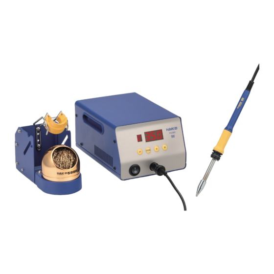
1. PACKING LIST Please check to make sure that all items listed below are included in the package. HAKKO FX-801 Station Power cord HAKKO FX-8002 Soldering iron Heat resistant pad Iron holder (with cleaning wire) Instruction manual Connecting cable HAKKO FX-8002... -
Page 3: Warnings, Cautions And Notes
● Do not modify the HAKKO FX-801. ● Use only genuine Hakko replacement parts. ● Do not allow the HAKKO FX-801 to become wet, or use it with wet hands. ● Remove power and iron cords by holding onto the plug. -
Page 4: Part Names
4. PART NAMES ● HAKKO FX-801 Preset number display Setting display Control buttons Power switch Receptacle Fuse Jack (for connecting cable) -
Page 5: Initial Setup
2. Set the iron in the iron holder. the plug. 3. Plug the power cord into a grounded wall socket. CAUTION The HAKKO FX-801 is protected against electrostatic discharge and must be grounded for full efficiency. -
Page 6: Operation
6. OPERATION The HAKKO FX-801 has the following four control buttons. Press for less than one second to enter preset number selection screen. Press and hold for at least one second to enter preset temperature changing screen. Use to increase the value in the appropriate display window. - Page 7 Changing temperature setting CAUTION The temperature setting range is from 50℃ to 500℃. (120℉ to 940℉) ●If you enter a value outside the temperature setting range, the display returns to the hundreds digit, and you have to enter a correct value. Example:Changing set temperature from 350 to 400℃...
- Page 8 Selecting the preset number You can quickly select one of six user programmable preset temperatures. Initial preset temperatures are: 0:300℃, 1:350℃, 2:375℃, 3:400℃, 4:450℃ and 5:500℃. Example:Changing preset No. 0 (300℃) to No. 3 (400℃) 1. Press the button once. ...
- Page 9 Entering the tip offset value Example:If the measured temperature is 410℃ and set temperature is 400℃, the difference is -10℃ (need to decrease by 10℃). So enter a value so 10 is deducted from present offset value. 1. Press and hold the button for at least one second.
- Page 10 Restriction on setting changes (Password function) It is possible to restrict certain setting changes to the unit. There are three choices for the password setting. (The factory default is "0 : Open") 0 : Open 1 : Partial 2 : Restricted Parameter setting mode ○...
-
Page 11: Parameter Setting
7. PARAMETER SETTING Parameter name Parameter number Settings Initial value Temperature display ℉( )/℃( ) ℃ (℉**) 6 min. Auto sleep time setting 0 - 29 min. 300℃ (540℉**) Low temperature error setting 30 - 300℃ (54 - 540℉) Buzzer setting OFF( )/ON( ) ON ( ) (S-E sound , C-E sound) ON ( ) - Page 12 ● : ℃ or ℉ temperature display selection 1. In display setting mode, either is displayed : The display shows temperatures in Celsius : The display shows temperatures in Fahrenheit will be switched alternately if you press the ( ) button. 3.
- Page 13 ● : Low temperature error setting When the temperature drops below a set limit, an error is displayed and the buzzer sounds. When the temperature returns within the allowable range, the buzzer stops. Low temperature setting range : for Celsius: 30 to 300ºC for Fahrenheit: 54 to 540ºF Example : When the set temperature is 350ºC and the low temperature error setting is 100ºC, a warning buzzer sounds when the temperature drops to 250ºC.
- Page 14 ● : Auto shutoff on/off setting When the auto shutoff function is set to on and no operation is performed for 30 minutes ( Initial value ) after the iron is set in the iron holder, the buzzer sounds and the auto shutoff function will be enabled.
- Page 15 ● : Password setting If selecting Restricted, perform the setting for password. If selecting Partial, choose whether or not the password function is needed when changing the set temperature, the preset number and the offset value and set the password. 1.
- Page 16 ● : Auto shutoff time setting Set auto shutoff time. The setting is possible within 30 to 60 minutes, in one minute increments. 1. Auto shutoff time (Initial value is 30 minutes) will be displayed if you press the button when is displayed.
-
Page 17: Maintenance
High temperatures shorten tip life and may cause thermal shock to components. Always use the lowest possible temperature when soldering. The excellent thermal recovery characteristics of the HAKKO FX-801 ensures effective soldering at low temperatures. 2. Cleaning Always clean the soldering iron tip before use, to remove any residual solder or flux adhering to it by using a tip cleaner. -
Page 18: Checking Procedure
9. CHECKING PROCEDURE WARNING Unless otherwise directed, carry out these procedures with power switch OFF and the power UNPLUGGED. ■Check for a broken heater or sensor Verify the electrical integrity of the heater and sensor. Measure the resistance of the heater and sensor while at room temperature (15℃ to 25℃; 59℉ to 77℉) It should be 3.4Ω±10%. -
Page 19: Error Messages
10. ERROR MESSAGES ● Sensor error When there is a possibility that a failure has occured in the sensor or heater (including the sensor circuit), is displayed and a buzzer sounds. ● Soldering iron error is displayed and a buzzer sounds if the iron cable is not attached to the station or a wrong soldering iron is connected. -
Page 20: Trouble Shooting Guide
11. TROUBLE SHOOTING GUIDE ● The unit does not operate when the power switch is turned ON. CHECK : Is the power cord and/or the connection plug disconnected? ACTION : Correctly connect the power cord. CHECK : Is the fuse down? ACTION :... - Page 21 ●The low-temperature alarm tolerance error is displayed frequently. CHECK : Is the tip too small for the work being soldered? ACTION : Use a tip with a larger thermal capacity. CHECK : Is the setting value for the low-temperature alarm tolerance too low? ACTION :...
-
Page 22: Parts List
12. PARTS LIST ● HAKKO FX-801 Part Name Specifications Item No. Part No. Item No. Part No. Part Name Specifications B3674 Fuse/250V-7A 100 - 120V B2424 Power cord, 3-wire 220V KTL cord & European plug 230V CE B3675 Fuse/250V-4A 220 - 240V... - Page 23 ● HAKKO FX-8002 Item No. Part No. Part Name Specifications See section "TIP STYLE" FX8002-81 HAKKO FX-8002 29V-260W 2 ∼ 4 B5071 Nipple 2 3 With O-ring B2578 O-ring B2300 Heat resistant pad ● Iron holder Item No. Part No. Part Name Specifications 1 ∼...
-
Page 24: Wiring Diagram
13. WIRING DIAGRAM Control P.W.B. Jack Power receptacle White Black Black Control power P.W.B. Power switch... - Page 25 TIP STYLES (4.02) Unit:mm (in.) T33-BC2 SHAPE-2BC T33-BC3 SHAPE-3BC T33-BC4 SHAPE-4BC (0.67) (0.51) (0.67) T33-BC5 SHAPE-5BC T33-BC6 SHAPE-6BC T33-D24 SHAPE-2.4D (0.51) (0.51) (0.04) (0.67) T33-D32 SHAPE-3.2D T33-D5 SHAPE-5D T33-D6 SHAPE-6D (0.04) (0.06) (0.06) (0.51) (0.51) (0.51) Test Equipment Depot - 800.517.8431 - 99 Washington Street Melrose, MA 02176 TestEquipmentDepot.com...
Need help?
Do you have a question about the FX-801 and is the answer not in the manual?
Questions and answers