Advertisement
Quick Links
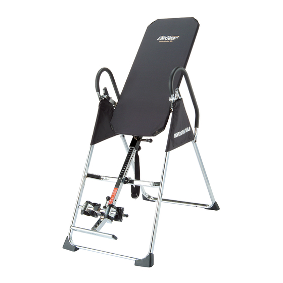
I I N N V V E E R R S S I I O O N N T T A A B B L L E E
OWNER'S MANUAL
MODEL#75112
CAUTION: Weight on this product should not exceed 136kgs (300lbs).
CAUTION: Exercise of a strenuous nature, as is customarily done on this equipment, should not be undertaken
without first consulting a physician. No specific health claims are made or implied as they relate to the
equipment. Measurements made by the equipment are believed to be accurate, but only the measurements of
your physician should be relied upon.
IMPORTANT:
Read all instructions carefully before using this product. Retain this owner's manual for future reference.
Instructions for assembly, including correct fitting of guards and other device, and warnings about the likely
injuries to young children if exercise equipments are operated in their vicinity without properly fitted guards.
Product may vary slightly from picture.
2015, Feb.
Advertisement

Related Manuals for Life Gear 75112


Summary of Contents for Life Gear 75112
- Page 1 I I N N V V E E R R S S I I O O N N T T A A B B L L E E OWNER’S MANUAL MODEL#75112 2015, Feb. CAUTION: Weight on this product should not exceed 136kgs (300lbs).
- Page 2 TABLE OF ONE YEAR WARNING CONTENTS LIMITED WARRANTY Warranty LifeGear Inc. warrants to the WARNING original purchaser that this Warning Before using this product, product is free from defects in Safety Precautions please consult your personal material and workmanship when Overview Drawing physician for a complete used for the purpose intended,...
- Page 3 SAFETY PRECAUTIONS This inversion table was designed and built for optimum safety. However, certain precautions apply whenever you operate the exercise equipment. Be sure to read the entire manual before assembling and operating this equipment. Also, please note the following safety instructions: 1.
- Page 4 SAFETY PRECAUTIONS...
- Page 5 OVERVIEW DRAWING...
- Page 7 PARTS LIST Part # Description Quantity Part # Description Quantity Front U-Frame Washer Ø 16xØ 6.5x1.0 Rear U-Frame Upper Bed Frame Bushing Adjustable Boom Handlebar Bed Frame Knob Pivot Arm Rubber Heel Holder Adjustable lnstep Frame Nylon Strap Steel Heel Holder Bracket Loop Strap Left Folding Arm Strap Lock...
- Page 8 HARDWARE PACKING LIST Part # Description Quantity Hex Head Bolt M6x47 -----------------------------------------------------------------------------------------2 Washer Ø 20xØ 8.5x1.5 ---------------------------------------------------------------------------------------12 Lock Nut M8 ------------------------------------------------------------------------------------------------------- 6 Lock Nut M6 ------------------------------------------------------------------------------------------------------- 2 Washer Ø 16xØ 6.5x1.0 ----------------------------------------------------------------------------------------4 Hex Head Bolt M8x23 -----------------------------------------------------------------------------------------2 Hex Head Bolt M8x50 -----------------------------------------------------------------------------------------2 Square End Cap -------------------------------------------------------------------------------------------------- 1 Hex Head Bolt M8x38 -----------------------------------------------------------------------------------------2 Bolt M6x20 --------------------------------------------------------------------------------------------------------- 8...
- Page 9 ASSEMBLY INSTRUCTIONS STEP 1: Lay down the base of the machine by separating the Front and Rear U-Frames (1, 2). Pull the Front and Rear U-Frames (1, 2) as far apart from each others as possible. Then push down on the middle of two Left and Right Folding Arms (8L, 8R) until they are fully locked down.
- Page 10 STEP 2: Install two Ø 27xØ 13.5 Nut Caps (53) onto M8 Lock Nuts (15). Slide one Protective Cover (37) on to each side of the base as shown, and pull down on the Protective Covers (37) until the bottom of the covers are slightly lower than the Left and Right Folding Arms (8L, 8R).
- Page 11 STEP 3: Slide the bottom of the Pivot Arms (5) into the brackets that located at each side of the Bed Frame (4), align to the desired hole on the arm with the peg on the bracket. Insert the peg into the hole to lock the Pivot Arms (5) in place.
- Page 12 STEP 5: Slide the Rod (9) through the large round hole on the side of the Adjustable Boom (3), and secure the Rod (9) on the Adjustable Boom (3) with one M6x47 Hex Head Bolt (11), one M6 Lock Nut (16), and two Ø...
- Page 13 STEP 7-1: Slide one Steel Heel Holder Bracket (7) and one Rubber Heel Holder (31) onto one end of the Adjustable Instep Frame (6) until the lock tooth is wedged into the slot in the Adjustable Instep Frame (6) as shown in figures A and B.
- Page 14 STEP 7-2: A. Pull the nylon strip on the ring of the Spring (23) to align the ring and holes on bracket. B. Insert the M6x47 Hex Head Bolt (11) with a Ø 16xØ 6.5x1.0 Washer (27) halfway through the square bracket, slide the M6x47 Hex Head Bolt (11) through the ring at the bottom of the Spring (23), slide the M6x47 Hex Head Bolt (11) through the rest of the square bracket, and secure at the other end with a Ø...
- Page 15 STEP 9: Attach the top end of Handlebar (29) onto the Rear U-Frame (2) and Pivot Arm Ring (54) with one M8x 23 Hex Head Bolt (38), one M8 Lock Nut (15), and two Ø 20xØ 8.5x1.5 Washers (13). Attach the bottom end of the Handlebar (29) onto the Rear U-Frame (2) with one M8x38 Hex Head Bolt (43), one M8 Lock Nut (15), and two Ø...
- Page 16 STEP 10: Attach the Nylon Strap (32) to the Strap Lock (34) by inserting the end of the Nylon Strap (32) up through the bottom of the Strap Lock (34), loop the Nylon Strap (32) over the Pre-assembled Loop Strap (33) and down through the Strap Lock (34). Now, loop the strap back over itself, and insert back through the Strap Lock (34), and pull tight to secure.
- Page 17 SAFETY OPERATING INSTRUCTIONS Correct Incorrect Pivot arm is NOT aligned correctly. Make sure the pivot arm is inserted all the The pivot arm is not inserted all the way into the slot. Pivot arm is aligned correctly way into the curved slot. when the groove sits directly on the curved slot and the pivot arm is able to rotate freely.
- Page 18 OPERATION AND ADJUSTMENTS LENGTHEN SHORTEN THE STRAP ADJUSTING THE STRAP For added safety, a nylon strap has been included to restrict the degree of inversion. This strap can be adjusted to different lengths to allow for a greater or lesser degree of inversion. To lengthen the Nylon Strap (32) feed the top end of Nylon Strap (32) into the strap lock, and pull on the lower end of the strap.
- Page 19 PIVOT ARMS The Pivot Arms (5) can be adjusted to allow for a greater or lesser degree of inversion. To adjust the Pivot Arms (5) simply pull out on them until the post is out of the hole, slide them up or down to the desired hole, push in until the post goes through the desired hole.
- Page 20 ADJUSTING THE ANGLE HOLDER Pull up on the Small Spring Knob (17), slide the Adjustable Instep Frame (6) upward. Stand on the Foot Bar (39) located at the bottom of the Adjustable Boom (3). Pull up on the Small Spring Knob (17), allow the Adjustable Instep Frame (6) to slide back into the Adjustable Boom (3).
- Page 21 BALANCING THE INVERSION TABLE The inversion table is like a very sensitively balanced fulcrum. It responds to very slight changes in weight distribution. So, it is very important to make sure that the height is adjusted properly. To do this, mount the inversion table, lock your ankles into the rubber heel holders, and lie back with your hands at your sides.
- Page 22 SUGGESTIONS FOR USE 1. Begin slowly: invert only 15~20 degrees to begin with. Stay inverted only as long as you are comfortable. Return upright slowly. 2. Make gradual changes: increase the angle only if it is comfortable. Increase angle only a few degrees at a time.
- Page 23 For your storage convenience, the inversion table can be folded down to place against a wall, under a bed, or in a storage area.
- Page 24 WARM UP AND COOL DOWN ROUTINE A good exercise program consists of a warm-up, aerobic exercise, and a cool down. Do the entire program at least two to three times a week, resting for a day between workouts. After several months you can increase your workouts to four or five times per week.
- Page 25 SIDE STRETCHES Open your arms to the side and lift them until they are over your head. Reach your right arm as far toward the ceiling as you can for one count. Repeat this action with your left arm. QUADRICEPS STRETCH With one hand against a wall for balance, reach behind you and pull your right foot up.
- Page 26 TOE TOUCHES Slowly bend forward from your waist, letting your back and shoulders relax as you stretch toward your toes. Reach as far as you can and hold for 15 counts. HAMSTRING STRETCHES Extend your right leg. Rest the sole of your left foot against your right inner thigh.
Need help?
Do you have a question about the 75112 and is the answer not in the manual?
Questions and answers