czech sport aircraft SportCruiser Maintenance Manual
Hide thumbs
Also See for SportCruiser:
- Maintenance manual (202 pages) ,
- Pilot operating handbook (113 pages) ,
- Operating handbook (92 pages)
Table of Contents
Advertisement
Quick Links
Download this manual
See also:
Operating Handbook
Advertisement
Chapters
Table of Contents

Related Manuals for czech sport aircraft SportCruiser


Summary of Contents for czech sport aircraft SportCruiser
- Page 1 SC-AMM-1-0-00 SportCruiser / PiperSport AIRPLANE MAINTENANCE MANUAL Revision No.: 5 Date of issue: 2015-05-24...
- Page 2 SC-AMM-1-0-00 INTENTIONALLY LEFT BLANK Date of issue: : 2015-05-24 Revision No.: 5...
- Page 3 SC-AMM-1-0-00 SportCruiser / PiperSport AIRPLANE MAINTENANCE MANUAL Czech Sport Aircraft a.s. Na Záhonech 1177/212, 686 04 Kunovice Czech Republic www. czechsportaircraft.com; office@czechsportaircraft.com Fax: +420 576 519 394, Phone: +420 576 514 034 (Sales Dept.) Revision No.: 5 Date of issue: 2015-05-24...
- Page 4 SC-AMM-1-0-00 INTENTIONALLY LEFT BLANK Date of issue: : 2015-05-24 Revision No.: 5...
- Page 5 SC-AMM-1-0-00 SportCruiser PiperSport RECORD OF REVISIONS Rev. Date and Revision name Changed pages Issue date signature Supplementation of LiFePo4 i, ii, iii, iv, 0-1, 0-5, 0-7, 2013-05-09 2013-09-05 battery 0-8, 0-9 Konečný Check of nose landing gear leg i, ii, iii, iv, 0-1, 0-5 to...
- Page 6 SC-AMM-1-0-00 SportCruiser PiperSport RECORD OF REVISIONS Rev. Date and Revision name Changed pages Issue date signature Revision No.: - Date of issue: 2013-06-30 0 - 2...
- Page 7 SC-AMM-1-0-00 SportCruiser PiperSport RECORD OF REVISIONS Rev. Date and Revision name Changed pages Issue date signature Date of issue: 2013-06-30 Revision No.: - 0 - 3...
- Page 8 SC-AMM-1-0-00 SportCruiser PiperSport RECORD OF REVISIONS Rev. Date and Revision name Changed pages Issue date signature Revision No.: - Date of issue: 2013-06-30 0 - 4...
-
Page 9: Sc-Amm-1
SC-AMM-1-0-00 SportCruiser PiperSport LIST OF EFFECTIVE PAGES Chapter Page Date Chapter Page Date Title 2015-05-24 2-10 2013-06-30 Page 2015-05-24 2-11 2013-06-30 2015-05-24 2-12 2013-06-30 2015-05-24 2-13 2013-06-30 2-14 2014-02-17 2015-05-24 2-15 2013-06-30 2013-06-30 2-16 2013-06-30 2013-06-30 2-17 2013-06-30 2013-06-30 2-18... - Page 10 SC-AMM-1-0-00 SportCruiser PiperSport LIST OF EFFECTIVE PAGES Chapter Page Date Chapter Page Date 2013-06-30 6-28 2013-06-30 2013-06-30 6-29 2013-06-30 2013-06-30 6-30 2013-06-30 2013-06-30 6-31 2013-06-30 2013-06-30 6-32 2013-06-30 2013-06-30 6-33 2013-06-30 2013-06-30 6-34 2013-06-30 2013-06-30 2013-06-30 5-10 2013-06-30 2013-06-30 5-11...
-
Page 11: Date Of Issue: 2014
SC-AMM-1-0-00 SportCruiser PiperSport LIST OF EFFECTIVE PAGES Chapter Page Date Chapter Page Date 8-19 2013-06-30 10-14 2013-06-30 8-20 2013-06-30 10-15 2013-06-30 8-21 2014-02-17 10-16 2013-06-30 8-22 2013-10-11 10-17 2013-06-30 8-23 2013-10-11 10-18 2013-06-30 8-24 2013-10-11 10-19 2013-06-30 8-25 2013-10-11 10-20... -
Page 12: Revision No
SC-AMM-1-0-00 SportCruiser PiperSport LIST OF EFFECTIVE PAGES Chapter Page Date Chapter Page Date 11-8 2013-06-30 12-29 2013-06-30 11-9 2013-06-30 12-30 2013-06-30 11-10 2013-09-05 12-31 2013-06-30 11-11 2013-09-05 12-32 2013-06-30 11-12 2013-09-05 12-33 2013-06-30 11-13 2013-09-05 12-34 2013-06-30 11-14 2013-09-05 12-35... - Page 13 SC-AMM-1-0-00 SportCruiser PiperSport LIST OF EFFECTIVE PAGES Chapter Page Date Chapter Page Date 13-1 2013-06-30 15-22 2013-06-30 13-2 2013-06-30 15-23 2013-06-30 13-3 2013-06-30 15-24 2013-06-30 13-4 2013-06-30 13-5 2013-06-30 13-6 2013-06-30 16-1 2013-06-30 13-7 2013-06-30 16-2 2013-06-30 13-8 2013-06-30 16-3...
-
Page 14: Revision No
SC-AMM-1-0-00 SportCruiser PiperSport LIST OF EFFECTIVE PAGES Chapter Page Date Chapter Page Date Revision No.: - Date of issue: 2013-06-30 0 - 10... - Page 15 SC-AMM-1-0-00 SportCruiser PiperSport CHAPTER 1 – GENERAL Chapter 1 - General................... 1-1 Chapter 2 - Limitations / Maintenance checks........2-1 Chapter 3 - Fuselage................. 3-1 Chapter 4 - Wing ..................4-1 Chapter 5 - Tail unit .................. 5-1 Chapter 6 - Control system ..............
- Page 16 SC-AMM-1-0-00 SportCruiser PiperSport CHAPTER 1 – GENERAL INTENTIONALLY LEFT BLANK Revision No.: - Date of issue: 2013-06-30 1 - 2...
-
Page 17: Table Of Contents
SC-AMM-1-0-00 SportCruiser PiperSport CHAPTER 1 – GENERAL Contents Introduction ......................1-5 Airplane Classification ................... 1-6 1.2.1 Power Unit ....................1-6 1.2.2 Main Technical Data ................. 1-7 Airplane Manufacturer and Type Certificate Holder ..........1-11 Chapter Order ...................... 1-11 1.4.1 Page Numbering..................1-11 Warnings, Cautions and Notes ................ - Page 18 SC-AMM-1-0-00 SportCruiser PiperSport CHAPTER 1 – GENERAL INTENTIONALLY LEFT BLANK Revision No.: - Date of issue: 2013-06-30 1 - 4...
-
Page 19: Introduction
CHAPTER 1 – GENERAL Introduction In accordance with requirements of the ASTM LSA regulations, the Czech Sport Aircraft a.s., as manufacturer of SportCruiser / PiperSport airplane, provides information on maintaining airworthiness of the SportCruiser / PiperSport airplane. Information is also contained in the... -
Page 20: Airplane Classification
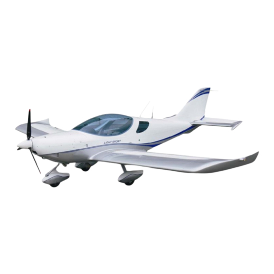
PiperSport CHAPTER 1 – GENERAL Airplane Classification SportCruiser / PiperSport airplane is two-seat, single engine, low-wing, all-metal airplane with fixed three-wheel landing gear. The airplane is designed for basic and advanced training and for leisure time flying. 1.2.1 Power Unit Power unit consists of: •... -
Page 21: Main Technical Data
SC-AMM-1-0-00 SportCruiser PiperSport CHAPTER 1 – GENERAL 1.2.2 Main Technical Data PiperSport / SportCruiser (early model) Wing • Span................8.810 m (28.90 ft) • Area................12.30 m (132.3 sq.ft) • MAC ................1,500 mm (59.1 in) • Wing loading ............. 49 kg/m (10.0 lb/sq.ft) - Page 22 SC-AMM-1-0-00 SportCruiser PiperSport CHAPTER 1 – GENERAL Fig. 1-1: SportCruiser / PiperSport Three-view drawing Revision No.: - Date of issue: 2013-06-30 1 - 8...
- Page 23 SC-AMM-1-0-00 SportCruiser PiperSport CHAPTER 1 – GENERAL SportCruiser (S/N P1102012, P1102014, P1102015, P1102016, P1102019, P1102027, P1102031, P1102034, C0416 and up) Wing • Span…………………………………………………..8.600 m (28.22 ft) • Area................12.30 m (132.3 sq.ft) • MAC ................1,500 mm (59.1 in) •...
- Page 24 SC-AMM-1-0-00 SportCruiser PiperSport CHAPTER 1 – GENERAL Fig. 1-2: SportCruisert Three-view drawing Revision No.: - Date of issue: 2013-06-30 1 - 10...
-
Page 25: Airplane Manufacturer And Type Certificate Holder
SC-AMM-1-0-00 SportCruiser PiperSport CHAPTER 1 – GENERAL Airplane Manufacturer and Type Certificate Holder Czech Sport Aircraft a.s. Na Záhonech 1177/212, 686 04 Kunovice Czech Republic www.czechsportaircraft.com; office@czechsportaircraft.com Fax: +420 576 519 394, Phone: +420 576 514 034 (Sales Dept.) Chapter Order Chapters in this manual are ordered in ascending sequence from No. -
Page 26: Equipment List
Refer to the SportCruiser / PiperSport Pilot′s Operating Handbook, Section 9 for actual Equipment list. Sources to Purchase Parts Spare parts can be ordered from CSA through the PS-28 Cruiser / SportCruiser / PiperSport Illustrated Parts Catalogue (Doc. No. CR-IPC-1-0-00). List of Disposable Replacement Parts... -
Page 27: General Safety Information
SC-AMM-1-0-00 SportCruiser PiperSport CHAPTER 1 – GENERAL 1.14 General Safety Information Safety must be considered the first priority when performing maintenance or service on an aircraft or part. To minimize the risk to both yourself and others, begin by thinking through each task that is to be performed before starting any work. -
Page 28: Definitions And Abbreviations
SC-AMM-1-0-00 SportCruiser PiperSport CHAPTER 1 – GENERAL 1.15 Definitions and abbreviations ACCU Accumulator ADAHRS Air Data Attitude and Heading Reference System Annual condition inspection detailed inspection accomplished once a year on a LSA in accordance with instructions provided in the maintenance manual supplied with the aircraft. The purpose of the inspection is to look for any wear, corrosion, or damage that would cause an aircraft to not be in a condition for safe operation. - Page 29 SC-AMM-1-0-00 SportCruiser PiperSport CHAPTER 1 – GENERAL Power unit (1 kW = 1.341 hp) liter (1 l = 0.22 UK gal = 0.264 US gal) pounds (1 lb = 0.4536 kg) force unit (1 lbf = 4.45 N) Line maintenance...
- Page 30 SC-AMM-1-0-00 SportCruiser PiperSport CHAPTER 1 – GENERAL Nautical Mile (1 NM = 1,852 m) Outside Air Temperature System is switched off or control element is in off-position System is switched on or control element is in on- position Overhaul maintenance, inspection, repair, or alterations that are only to be accomplished...
- Page 31 SC-AMM-1-0-00 SportCruiser PiperSport CHAPTER 2 – TIME LIMITS / MAINTENANCE CHECKS Contents General ........................2-3 Airframe life limitation .................... 2-3 Aircraft parts life limitation..................2-3 Ordering spare parts ....................2-4 Terms and list of aircraft regular maintenance works..........2-4 2.5.1 General .....................
- Page 32 SC-AMM-1-0-00 SportCruiser PiperSport CHAPTER 2 – TIME LIMITS / MAINTENANCE CHECKS INTENTIONALLY LEFT BLANK Revision No.: - Date of issue: 2013-06-30 2 - 2...
-
Page 33: General
SC-AMM-1-0-00 SportCruiser PiperSport CHAPTER 2 – TIME LIMITS / MAINTENANCE CHECKS General This chapter contains information about: • airframe life limitations • aircraft parts life limitations • terms and list of aircraft regular maintenance works • lubrication chart Airframe life limitation Initial airframe life is 5,000 FH. -
Page 34: Ordering Spare Parts
2.5.1 General Authorization to perform Time Limits/Maintenance Checks and Inspections: Repairman (LS-M) or Mechanic (A&P) Maintenance system serves to maintain flight airworthiness of the SportCruiser / PiperSport airplane. Maintenance system is composed of special and scheduled inspections, which must be... -
Page 35: Tables Of Inspection Tasks
SC-AMM-1-0-00 SportCruiser PiperSport CHAPTER 2 – TIME LIMITS / MAINTENANCE CHECKS INTERVAL, MUST INCLUDED TIME FLOWN DETERMINATION OF THE NEXT 100-FH INSPECTION. (g) Scheduled annual inspection contains works of 100-FH inspection and other specified works (inspections of airframe, engine and propeller). - Page 36 SC-AMM-1-0-00 SportCruiser PiperSport CHAPTER 2 – TIME LIMITS / MAINTENANCE CHECKS SPECIAL INSPECTION AFTER FIRST 25 FH Aircraft S/N: ………………… TSN (FH): ………… Registration mark: ………………… TSN (cycles): ………… Page: 1 of 1 Chpt. Prescribed works Made by Checked by...
- Page 37 SC-AMM-1-0-00 SportCruiser PiperSport CHAPTER 2 – TIME LIMITS / MAINTENANCE CHECKS SCHEDULED SPECIAL INSPECTION Aircraft S/N: ………………… TSN (FH): ………… Registration mark: ………………… TSN (cycles): ………… Page: 1 of 1 Chpt. Prescribed works Made by Checked by Klassic 170 /3/R propeller 50 FH inspection Remove the propeller spinner.
- Page 38 SC-AMM-1-0-00 SportCruiser PiperSport CHAPTER 2 – TIME LIMITS / MAINTENANCE CHECKS SCHEDULED INSPECTION AFTER 25 FH or 50 cycles whatever occurs first Aircraft S/N: ………………… TSN (FH): ………… Registration mark: ………………… TSN (cycles): ………… Page: 1 of 1 Chpt. Prescribed works...
- Page 39 SC-AMM-1-0-00 SportCruiser PiperSport CHAPTER 2 – TIME LIMITS / MAINTENANCE CHECKS SCHEDULED INSPECTION AFTER 50 FH Aircraft S/N: ………………… TSN (FH): ………… Registration mark: ………………… TSN (cycles): ………… Page: 1 of 1 Chpt. Prescribed works Made by Checked by Landing Gear...
- Page 40 SC-AMM-1-0-00 SportCruiser PiperSport CHAPTER 2 – TIME LIMITS / MAINTENANCE CHECKS SCHEDULED ANNUAL PERIODICAL INSPECTION OR INSPECTION AFTER 100 FH Aircraft S/N: ………………… ………… TSN (FH): Registration mark: ………………… TSN (cycles): ………… Type of inspection: ………………… Page: 1 of 7 Chpt.
- Page 41 SC-AMM-1-0-00 SportCruiser PiperSport CHAPTER 2 – TIME LIMITS / MAINTENANCE CHECKS SCHEDULED ANNUAL PERIODICAL INSPECTION OR INSPECTION AFTER 100 FH Page: 2 of 7 Chpt. Prescribed works Made by Checked by Wing Visually check surface condition - loosened rivets, deformation, cracks and some other damage.
- Page 42 SC-AMM-1-0-00 SportCruiser PiperSport CHAPTER 2 – TIME LIMITS / MAINTENANCE CHECKS SCHEDULED ANNUAL PERIODICAL INSPECTION OR INSPECTION AFTER 100 FH Page: 3 of 7 Chpt. Prescribed works Made by Checked by Tail Unit (continued) Check for free travel of the rudder.
- Page 43 SC-AMM-1-0-00 SportCruiser PiperSport CHAPTER 2 – TIME LIMITS / MAINTENANCE CHECKS SCHEDULED ANNUAL PERIODICAL INSPECTION OR INSPECTION AFTER 100 FH Page: 4 of 7 Chpt. Prescribed works Made by Checked by Equipment (continued) Check attachment, security and routing of BRS activating handle.
- Page 44 SC-AMM-1-0-00 SportCruiser PiperSport CHAPTER 2 – TIME LIMITS / MAINTENANCE CHECKS SCHEDULED ANNUAL PERIODICAL INSPECTION OR INSPECTION AFTER 100 FH Page: 5 of 7 Chpt. Prescribed works Made by Checked by Fuel System Drain fuel tanks and gascolator (see 9.5.2).
- Page 45 SC-AMM-1-0-00 SportCruiser PiperSport CHAPTER 2 – TIME LIMITS / MAINTENANCE CHECKS SCHEDULED ANNUAL PERIODICAL INSPECTION OR INSPECTION AFTER 100 FH Page: 6 of 7 Chpt. Prescribed works Made by Checked by Electrical System Check attachment and condition of battery. Check level of battery charge.
- Page 46 SC-AMM-1-0-00 SportCruiser PiperSport CHAPTER 2 – TIME LIMITS / MAINTENANCE CHECKS SCHEDULED ANNUAL PERIODICAL INSPECTION OR INSPECTION AFTER 100 FH Page: 7 of 7 Chpt. Prescribed works Made by Checked by Operational and Functional Tests Check the function of the interior and exterior lighting.
-
Page 47: Lubrication Chart
SC-AMM-1-0-00 SportCruiser PiperSport CHAPTER 2 – TIME LIMITS / MAINTENANCE CHECKS Lubrication chart After first Every Every Unit Area of lubrication Lubricant 25 FH 100 FH 500 FH Throttle control cable on the inlet into LPS1 terminal (in the engine compartment). - Page 48 SC-AMM-1-0-00 SportCruiser PiperSport CHAPTER 2 – TIME LIMITS / MAINTENANCE CHECKS After first Every Every Unit Area of lubrication Lubricant 25 FH 100 FH 500 FH AeroShell Hinges. Grease 22 AeroShell Rod end bearings of the control tubes. Grease 22...
- Page 49 SC-AMM-1-0-00 SportCruiser PiperSport CHAPTER 2 – TIME LIMITS / MAINTENANCE CHECKS After first Every Every Unit Area of lubrication Lubricant 25 FH 100 FH 500 FH AeroShell Rudder hinges. Grease 22 Cable shackles on the rudder control AeroShell cables. Grease 22 Trim Tabs hinges.
- Page 50 SC-AMM-1-0-00 SportCruiser PiperSport CHAPTER 2 – TIME LIMITS / MAINTENANCE CHECKS After first Every Every Unit Area of lubrication Lubricant 25 FH 100 FH 500 FH Aileron, AeroShell elevator All movable links in the cockpit. Grease 22 control AeroShell All movable links in the cockpit.
- Page 51 SC-AMM-1-0-00 SportCruiser PiperSport CHAPTER 3 – FUSELAGE Contents General ........................3-3 Description and operation..................3-3 3.2.1 Front part of the fuselage ..............3-3 3.2.2 Rear part of the fuselage ............... 3-3 3.2.3 Cockpit....................3-4 3.2.4 Baggage compartment ................3-5 3.2.5 Crew canopy..................
- Page 52 SC-AMM-1-0-00 SportCruiser PiperSport CHAPTER 3 – FUSELAGE INTENTIONALLY LEFT BLANK Revision No.: - Date of issue: 2013-06-30 3 - 2...
-
Page 53: General
CHAPTER 3 – FUSELAGE General SportCruiser / PiperSport fuselage is a semi-monocoque structure formed by stiffeners and aluminum sheet. The fuselage consists of the front part with the cockpit and the rear part, the integral part of which is the fin. -
Page 54: Cockpit
SC-AMM-1-0-00 SportCruiser PiperSport CHAPTER 3 – FUSELAGE 1 Nose landing gear attachments 2 Wing attachment, main 3 Wing attachment, rear 4 Main landing gear attachments 5 Engine mount attachments 6 Rudder attachments 7 Stabilizer attachments Fig. 3-2: Fuselage monocoque 3.2.3 Cockpit The cockpit (see Fig. -
Page 55: Baggage Compartment
SC-AMM-1-0-00 SportCruiser PiperSport CHAPTER 3 – FUSELAGE 3.2.4 Baggage compartment Baggage compartment (8, Fig. 3-3) is located between the seats and the bulkhead No. 7. Max. baggage weight transported in the baggage compartment is 18 kg (40 lbs). 3.2.5 Crew canopy The crew canopy is produced of organic glass and consists of opening canopy and rear fixed canopy windows. -
Page 56: Canopy
(9, Fig. 3-3) and sliding ventilation windows located on both sides of the canopy. For newer models of the SportCruiser airplane closing and securing of the canopy is sensed by one terminal switch, located at the inside opening lever between the seats (see Wiring Manual). -
Page 57: Removal / Installation
SC-AMM-1-0-00 SportCruiser PiperSport CHAPTER 3 – FUSELAGE Removal / Installation 3.3.1 Canopy removal Type of maintenance: line Authorization to perform: Sport pilot, Repairman (LS-M) or Mechanic (A&P) Tools needed: socket wrench 7/16” screwdriver pliers CAUTION: DURING CANOPY REMOVAL BE CAREFULLY TO AVOID SCRATCHING THE GLASS. -
Page 58: Gas Strut Removal
SC-AMM-1-0-00 SportCruiser PiperSport CHAPTER 3 – FUSELAGE NOTE Access to the nuts (5) and washers (6) is from the cockpit. 1 Canopy 5 Nut 2 Gas strut 6 Washer 3 Dummy plug 7 Handle 4 Bolt Fig. 3-4: Canopy removal / installation 3.3.3 Gas strut removal... -
Page 59: Gas Strut Installation
SC-AMM-1-0-00 SportCruiser PiperSport CHAPTER 3 – FUSELAGE 1 Gas strut 2 Ball joint end fitting 3 Safety clip 4 Ball stud 5 Canopy frame 6 Fixed frame Fig. 3-5: Gas strut removal / installation 3.3.4 Gas strut installation Type of maintenance: line Authorization to perform: Sport pilot, Repairman (LS-M) or Mechanic (A&P) -
Page 60: Cabin Lock Installation
SC-AMM-1-0-00 SportCruiser PiperSport CHAPTER 3 – FUSELAGE (b) Remove the lock (1). 1 Lock 2 Screw Fig 3-6: Canopy lock removal / installation 3.3.6 Cabin lock installation Type of maintenance: line Authorization to perform: Sport pilot, Repairman (LS-M) or Mechanic (A&P) - Page 61 SC-AMM-1-0-00 SportCruiser PiperSport CHAPTER 3 – FUSELAGE CAUTION: USE ONLY ONE BALANCE BALLAST, NOT THEIR COMBINATION. MAX. WEIGHT OF BALLAST IS 0.8 KG. (a) By weighing or computation determine the mass of required ballast (mass of ballast: 0.25 kg or 0.5 kg or 0.8 kg; arm of ballast: 4,545 mm). Weighing process is given in the POH, Section 6.
-
Page 62: Check / Adjustment
SC-AMM-1-0-00 SportCruiser PiperSport CHAPTER 3 – FUSELAGE Check / Adjustment 3.4.1 Canopy lock adjustment Adjust the locks so that the canopy could be locked freely. Set the length of the rod. 3.4.2 Towing gear control cable adjustment Adjust the length of towing gear control cable so that the control lever and hook lever in the open position touched the stops. - Page 63 SC-AMM-1-0-00 SportCruiser PiperSport CHAPTER 4 - WING Contents General ........................4-3 Description and operation..................4-3 4.2.1 Wing ...................... 4-3 4.2.2 Wing flaps....................4-4 4.2.3 Ailerons....................4-5 4.2.4 Fuel tanks ....................4-6 4.2.5 Wing lockers ..................4-6 Removal / Installation .................... 4-6 4.3.1...
- Page 64 SC-AMM-1-0-00 SportCruiser PiperSport CHAPTER 4 - WING INTENTIONALLY LEFT BLANK Revision No.: - Date of issue: 2013-06-30 4 - 2...
-
Page 65: General
SC-AMM-1-0-00 SportCruiser PiperSport CHAPTER 4 - WING General SportCruiser / PiperSport wing is an aluminum structure and is equipped with flaps, ailerons and fuel tanks. This chapter describes the structure of: • wings • wing flaps • ailerons • fuel tanks Fig. -
Page 66: Wing Flaps
SC-AMM-1-0-00 SportCruiser PiperSport CHAPTER 4 - WING 1 Aileron 6 Position light 2 Flap 7 Wing locker 3 Wing tip 8 Fuel quantity sensor cover 4 Front attachment 9 Filler cap 5 Rear attachment Fig. 4-2: Wing, left 4.2.2 Wing flaps Flaps are of all-metal structure consisting of the skin (1, Fig. -
Page 67: Ailerons
SC-AMM-1-0-00 SportCruiser PiperSport CHAPTER 4 - WING 1 Flap skin 2 Flap rib 3 Guiding plate 4 Flap hinge Fig. 4-3: Wing flap, left 4.2.3 Ailerons Ailerons (Fig. 4-4) are of aluminum structure consisting of the skin (1) aluminum sheet metal, spar and ribs (2) which are connected by means of riveting. -
Page 68: Fuel Tanks
SC-AMM-1-0-00 SportCruiser PiperSport CHAPTER 4 - WING 4.2.4 Fuel tanks Fuel tanks are of welded all-metal structure consisting of aluminum sheet metal skin (1, Fig. 4- 5) and two ribs (2). There are on each tank filler neck (3), fuel quantity sensor (4), venting tube (5), finger screen (6) and drain valve (7). -
Page 69: Wing Installation
CHAPTER 4 - WING (d) Remove bushes (24, Fig. 4-6) (if installed) from the aileron control push rod (valid for SportCruiser airplanes from S/N C0416). (e) Remove cover (11, Fig. 4-7) on the bottom wing root. (f) Disconnect rear attachment bolts on rear spar. - Page 70 (l) Install bushes (24, Fig. 4-6) (if installed) to the aileron control push rod (valid for SportCruiser airplanes from S/N C0416). (m) Perform check the trim tab operation, flaps and ailerons deflections (see 6.4.3), possibly adjusting of theirs deflections (see 6.4.4).
-
Page 71: Wing Flap Removal
SC-AMM-1-0-00 SportCruiser PiperSport CHAPTER 4 - WING 4.3.3 Wing flap removal Type of maintenance: line Authorization to perform: Repairman (LS-M) or Mechanic (A&P) Tools needed: wrench size 7/16 in (a) Open the flap (1, Fig, 4-7) in full position. (b) Unscrew the nuts (5), remove the washers (6), bolts (4) and disconnect both flap hinges;... -
Page 72: Wing Flap Installation
SC-AMM-1-0-00 SportCruiser PiperSport CHAPTER 4 - WING 4.3.4 Wing flap installation Type of maintenance: line Authorization to perform: Repairman (LS-M) or Mechanic (A&P) Tools needed: wrench size 7/16 in (a) Clean all attachments and apply lubricant on it (see 2.6). Do the same for the hinges on the wing. -
Page 73: Aileron Installation
SC-AMM-1-0-00 SportCruiser PiperSport CHAPTER 4 - WING 4.3.6 Aileron installation Type of maintenance: heavy Authorization to perform: Repairman (LS-M) or Mechanic (A&P) Tools needed: wrench size 7/16 in pliers (a) Clean all attachments and apply lubricant on it (see 2.6). Do the same for the hinges on the wing. -
Page 74: Check / Adjustment
SC-AMM-1-0-00 SportCruiser PiperSport CHAPTER 4 - WING Check / Adjustment No procedures included. Exchanges / Service information No procedures included. Revision No.: - Date of issue: 2013-06-30 4 - 12... - Page 75 SC-AMM-1-0-00 SportCruiser PiperSport CHAPTER 5 – TAIL UNIT Contents General ........................5-3 Description and operation..................5-3 5.2.1 Horizontal stabilizer ................5-3 5.2.2 Elevator with tabs .................. 5-4 5.2.3 Fin......................5-5 5.2.4 Rudder ....................5-6 Removal / Installation .................... 5-7 5.3.1 Horizontal stabilizer removal ..............
- Page 76 SC-AMM-1-0-00 PS-28 Cruiser SportCruiser CHAPTER 5 – TAIL UNIT INTENTIONALLY LEFT BLANK Revision No.: - Date of issue: 2013-06-30 5 - 2...
-
Page 77: General
SC-AMM-1-0-00 SportCruiser PiperSport CHAPTER 5 – TAIL UNIT General Tail unit of SportCruiser / PiperSport airplane is of all-metal structure and is composed of: • stabilizer • elevator with tabs • • rudder. Description and operation 5.2.1 Stabilizer Stabilizer (1, Fig. 5-1) is of the all-metal structure consisting of the two spars, ribs and aluminum skin. -
Page 78: Elevator With Tabs
Mass balances (6) are riveted at the both elevator ends and covered composite tips (7). The elevator is equipped with the trim tab (2); newer SportCruiser airplanes also have balance tab (3). Both tabs are hinged by means of the piano hinge on the rear spar close to the trailing edge of the elevator. -
Page 79: Fin
SC-AMM-1-0-00 SportCruiser PiperSport CHAPTER 5 – TAIL UNIT 5.2.3 Fin The vertical fin (1, Fig. 5-3) is of an aluminum structure and is an integral part with the rear part of the fuselage. The fin consists of stiffeners, spar, ribs and aluminum skin. Individual parts are assembled by riveting. -
Page 80: Rudder
Individual parts are assembled by riveting. On the spar are two attachments lower one (3) and upper one (2) for the rudder suspension on the fin. Control lever (4) is riveted on root rib. On the trailing edge is riveted fixed trim tab (6) – only newer SportCruiser airplanes. 1 Rudder... -
Page 81: Removal / Installation
SC-AMM-1-0-00 SportCruiser PiperSport CHAPTER 5 – TAIL UNIT Removal / Installation 5.3.1 Horizontal stabilizer removal Type of maintenance: heavy Authorization to perform: Repairman (LS-M) or Mechanic (A&P) Tools needed: wrench size 7/16 in screwdriver cutting pliers NOTE: For stabilizer removal three persons are requested. - Page 82 SC-AMM-1-0-00 PS-28 Cruiser SportCruiser CHAPTER 5 – TAIL UNIT (i) Perform check the trim tab operation and elevator deflections (see 6.4.3), possibly adjusting of elevator deflections (see 6.4.4). Fig. 5-5: Stabilizer, elevator removal / installation (page 1 of 2) Revision No.: -...
-
Page 83: Elevator Removal
SC-AMM-1-0-00 SportCruiser PiperSport CHAPTER 5 – TAIL UNIT 1 Stabilizer 14 Nut 2 Elevator 15 Washer 3 Rear cover 16 Bolt 4 Bolt 17 Elevator control rod 5 Stabilizer fairing 18 Bolt 6 Bolt 19 Nut 7 Pin - front stabilizer hinge... -
Page 84: Trim Tab Removal
SC-AMM-1-0-00 PS-28 Cruiser SportCruiser CHAPTER 5 – TAIL UNIT NOTE: For elevator installation two persons are requested. (a) Inspect the hinges on the elevator, clean them and apply lubricant on them (see 2.6). Do the same for the hinges on the stabilizer. - Page 85 SC-AMM-1-0-00 SportCruiser PiperSport CHAPTER 5 – TAIL UNIT 1 Trim tab Piano hinge 2 Control lever Rivet 3 Pin Balance tab 4 Washer 10 Control lever 5 Cotter pin 11 Control rod 6 Control rod Fig. 5-6: Elevator tabs removal / installation Date of issue: 2013-06-30 Revision No.: -...
-
Page 86: Balance Tab Removal
SC-AMM-1-0-00 PS-28 Cruiser SportCruiser CHAPTER 5 – TAIL UNIT 5.3.7 Balance tab removal Type of maintenance: heavy Authorization to perform: Repairman (LS-M) or Mechanic (A&P) Tools needed: pliers, cutting pliers electric drill, drill diam. 3.2 mm (1/8 in) (a) Remove cotter pin (5, Fig. 5-6), washers (4), pin (3) and disconnect control rod (11) from the tab control lever (10). -
Page 87: Rudder Installation
SC-AMM-1-0-00 SportCruiser PiperSport CHAPTER 5 – TAIL UNIT 5.3.10 Rudder installation Type of maintenance: heavy Authorization to perform: Repairman (LS-M) or Mechanic (A&P) Tools needed: wrench size 3/8 in, 7/16 in NOTE: For rudder installation two persons are requested. (a) Inspect the hinges on the rudder, clean them and apply lubricant on them (see 2.6). Do the same for the hinges on the fin. -
Page 88: Check / Adjustment
SC-AMM-1-0-00 PS-28 Cruiser SportCruiser CHAPTER 5 – TAIL UNIT 1 Rudder 6 Bolt 2 Bolt 7 Nut 3 Nut 8 Washer 4 Washer 9 Cotter pin 5 Rudder control cable Fig. 5-7: Rudder removal / installation Check / Adjustment No procedures included. - Page 89 SC-AMM-1-0-00 SportCruiser PiperSport CHAPTER 6 – CONTROL SYSTEM Contents General ........................6-3 Description and operation..................6-3 6.2.1 Lateral control..................6-3 6.2.2 Longitudinal control ................6-4 6.2.3 Directional control.................. 6-4 6.2.4 Elevator and aileron trim tab control............6-5 6.2.5 Wing flap control..................6-6 6.2.6...
- Page 90 SC-AMM-1-0-00 SportCruiser PiperSport CHAPTER 6 – CONTROL SYSTEM Check / Adjustment....................6-27 6.4.1 Check of play in control ............... 6-27 6.4.2 Check for friction in control system ............. 6-28 6.4.3 Checking control surface deflections........... 6-29 6.4.4 Adjustment of control surface deflections ........... 6-32 6.4.5...
-
Page 91: General
SC-AMM-1-0-00 SportCruiser PiperSport CHAPTER 6 – CONTROL SYSTEM 6.1 General SportCruiser / PiperSport airplane is equipped with dual controls which enables pilot training. Airplane control includes: • lateral control (aileron control) • longitudinal control (elevator control) • directional control (rudder control) •... -
Page 92: Longitudinal Control
SC-AMM-1-0-00 SportCruiser PiperSport CHAPTER 6 – CONTROL SYSTEM 6.2.2 Longitudinal control The elevator is controlled by control sticks. Movement of control sticks is transferred by system of transmission levers and push rods to the elevator. Forward and backward movement of the control stick is transferred by the push rod lead through the central channel between seats to the two-arm lever which is located under the baggage floor. -
Page 93: Elevator And Aileron Trim Tab Control
SC-AMM-1-0-00 SportCruiser PiperSport CHAPTER 6 – CONTROL SYSTEM Fig. 6-3: Directional control scheme 6.2.4 Elevator and aileron trim tab control The elevator and aileron trim tabs are controlled by the electrical actuators installed in elevator/right aileron and connected per threaded rod with trim tab. Control switches are integrated part of grips. -
Page 94: Wing Flap Control
SC-AMM-1-0-00 SportCruiser PiperSport CHAPTER 6 – CONTROL SYSTEM 6.2.5 Wing flap control Wing flaps are controlled by electric flaps actuator connected with flaps per torque tube with control pins on each end. The flaps actuator located in fuselage under floor of baggage space and is controlled by a rocker switch located in cockpit. -
Page 95: Autopilot System
SC-AMM-1-0-00 SportCruiser PiperSport CHAPTER 6 – CONTROL SYSTEM 6.2.6 Autopilot system The EFIS D100 autopilot system is a digital flight control system that provides roll and pitch control. The system has the following components: - EFIS D100 - AP74 autopilot interface module... -
Page 96: Removal / Installation
SC-AMM-1-0-00 SportCruiser PiperSport CHAPTER 6 – CONTROL SYSTEM 6.3 Removal / Installation 6.3.1 General principles for work on control system Push rod assembly Type of maintenance: heavy Authorization to perform: Repairman (LS-M) or Mechanic (A&P) Tools needed: wrench size 7/16 in Set the push rods to the prescribed length before assembling, tighten the nuts slightly, and do not secure them for the time being. -
Page 97: Control Stick Installation
SC-AMM-1-0-00 SportCruiser PiperSport CHAPTER 6 – CONTROL SYSTEM (b) Unscrew the nuts (17), remove the washers (18) and disconnect the aileron control rods (4) from sticks (2); remove the cases (19). (c) Remove the grips (3) and disconnect wires (24) for trim tab switches and PTT on the grips. - Page 98 SC-AMM-1-0-00 SportCruiser PiperSport CHAPTER 6 – CONTROL SYSTEM 1 Transmission tube 14 Washer 2 Control stick 15 Nylon washer 3 Grip 16 Cotter pin 4 Aileron control rod 17 Nut 5 Bolt 18 Washer 6 Nut 19 Case 7 Washer...
-
Page 99: Flap Control Actuator Removal
SC-AMM-1-0-00 SportCruiser PiperSport CHAPTER 6 – CONTROL SYSTEM 6.3.4 Flap control actuator removal Type of maintenance: line Authorization to perform: Repairman (LS-M) or Mechanic (A&P) Tools needed: wrench size 7/16 in, 1/2 in, screwdriver (a) Set the flap to the landing position; switch off electrical power of the airplane. -
Page 100: Flap Control Actuator Installation
SC-AMM-1-0-00 SportCruiser PiperSport CHAPTER 6 – CONTROL SYSTEM 6.3.5 Flap control actuator installation Type of maintenance: line Authorization to perform: Repairman (LS-M) or Mechanic (A&P) Tools needed: wrench size 7/16 in, 1/2 in, screwdriver (a) Fit the flap actuator (1, Fig. 6-8) to the actuator hinge (10), insert the bolt (3) to the hole, install the washer (5), screw and tighten the nut (4). -
Page 101: Trim Tab Control Actuator Installation
SC-AMM-1-0-00 SportCruiser PiperSport CHAPTER 6 – CONTROL SYSTEM 6.3.7 Trim tab control actuator installation Type of maintenance: heavy Authorization to perform: Repairman (LS-M) or Mechanic (A&P) Tools needed: wrench size No.5 screwdriver pliers pliers for riveting (a) Fit the rod (6, Fig. 6-9) to the actuator rod, insert pin (7) with washer (8) into the hole, insert the washer (5) and secure with the new cotter pin (9). -
Page 102: Removal Of Aileron Control Lever Behind The Seats
SC-AMM-1-0-00 SportCruiser PiperSport CHAPTER 6 – CONTROL SYSTEM NOTE Figure shows the elevator trim tab control actuator. 1 Trim tab control actuator Pin (2 pcs.) 2 Actuator wires Washer (2 pcs.) 3 Screw Cotter pin (2 pcs.) 4 Nut 10 Cover 5 Washer 11 Rivet (9 pcs.) -
Page 103: Installation Of Aileron Control Lever Behind The Seats
SC-AMM-1-0-00 SportCruiser PiperSport CHAPTER 6 – CONTROL SYSTEM 6.3.9 Installation of aileron control lever behind the seats Type of maintenance: heavy Authorization to perform: Repairman (LS-M) or Mechanic (A&P) Tools needed: wrench size 7/16 in (a) Check condition of the control lever and lubrication of the friction surfaces. If the friction surfaces are contaminated, then carefully remove contamination and grease them with lubricant (see 2.6). -
Page 104: Removal Of Aileron Control Bell Crank In The Wing
SC-AMM-1-0-00 SportCruiser PiperSport CHAPTER 6 – CONTROL SYSTEM 1 Two-arm lever 2 Bolt 10 Washer 3 Nut 11 Nylon washer 4 Washer 12 Cotter pin 5 Bolt 13 Control rod I 6 Nut 14 Control rod II 7 Washer For information:... - Page 105 SC-AMM-1-0-00 SportCruiser PiperSport CHAPTER 6 – CONTROL SYSTEM NOTE: The bell cranks located on the bracket in the position of the rear rib No. 7 between the spars. Removal is identical for the left and the right aileron bell crank.
-
Page 106: Installation Of Aileron Control Bell Crank In The Wing
SC-AMM-1-0-00 SportCruiser PiperSport CHAPTER 6 – CONTROL SYSTEM 6.3.11 Installation of aileron control bell crank in the wing Type of maintenance: heavy Authorization to perform: Repairman (LS-M) or Mechanic (A&P) Tools needed: wrench size 7/16 in screwdriver NOTE: Installation is identical for the left and the right aileron bell crank. -
Page 107: Removal Of Middle Two-Arm Lever
SC-AMM-1-0-00 SportCruiser PiperSport CHAPTER 6 – CONTROL SYSTEM 6.3.12.2 Removal of middle two-arm lever (a) Remove the front cover (between bulkheads No. 8 and 9) at the bottom of the fuselage rear part. (b) Unscrew the nuts (5, Fig. 6-12), remove washers (6) and bolts (4) and disconnect rods (13;... -
Page 108: Installation Of Middle Two-Arm Lever
SC-AMM-1-0-00 SportCruiser PiperSport CHAPTER 6 – CONTROL SYSTEM 6.3.13.2 Installation of middle two-arm lever (a) Check condition of the control lever and lubrication of the friction surfaces. If the friction surfaces are contaminated, then carefully remove contamination and grease them with lubricant (see 2.6). - Page 109 SC-AMM-1-0-00 SportCruiser PiperSport CHAPTER 6 – CONTROL SYSTEM 1 Front two-arm lever 11 Cotter pin 2 Middle two-arm lever 12 Front control rod I 3 Rear two-arm lever 13 Front control rod II 4 Bolt 14 Middle control rod 5 Nut...
-
Page 110: Autopilot Servos Removal
SC-AMM-1-0-00 SportCruiser PiperSport CHAPTER 6 – CONTROL SYSTEM 6.3.14 Autopilot servos removal Type of maintenance: heavy Authorization to perform: Repairman (LS-M) or Mechanic (A&P) Tools needed: wrench size 7/16 in screwdriver pliers drill diam. 3.2 mm (1/8 in) electric drill... -
Page 111: Autopilot Servos Installation
SC-AMM-1-0-00 SportCruiser PiperSport CHAPTER 6 – CONTROL SYSTEM 1 Roll servo 2 Servo wires 3 Bracket 4 Bolt (4 pcs) 5 Washer (3 pcs) 6 Washer 7 Bolt (2 pcs) 8 Washer (2 pcs) 9 Stop (i) Fig. 6-13: Roll servo removal 6.3.15 Autopilot servos installation... -
Page 112: Installation Of Roll Servo
SC-AMM-1-0-00 SportCruiser PiperSport CHAPTER 6 – CONTROL SYSTEM 6.3.15.1 Installation of roll servo (a) Rivet the new bracket (3, Fig. 6-14) on the rear seat stiffener angle and lower fuselage skin. (b) Insert the servo (1) to the servo base (9), insert the bolts (4) with the washers (5; 6) to the holes and tighten the bolts;... - Page 113 SC-AMM-1-0-00 SportCruiser PiperSport CHAPTER 6 – CONTROL SYSTEM 1 Roll servo 13 Rod 2 Servo wires 14 Bolt 3 Bracket 15 Nut 4 Bolt (4 pcs) 16 Washer 5 Washer (3 pcs) 17 Bolt 6 Washer 18 Nut 7 Bolt (2 pcs)
- Page 114 SC-AMM-1-0-00 SportCruiser PiperSport CHAPTER 6 – CONTROL SYSTEM NOTE The nuts (22) and the washers (23) are on the fuselage bottom side. 1 Pitch servo 15 Nut 2 Stop 16 Washer 3 Bolt (4 pcs) 17 Bolt 4 Washer (3 pcs)
-
Page 115: Check / Adjustment
SC-AMM-1-0-00 SportCruiser PiperSport CHAPTER 6 – CONTROL SYSTEM 6.4 Check / Adjustment 6.4.1 Check of play in control Admissible plays in control are mentioned in the following table: Control Admissible play Area to measure play longitudinal max 4 mm (5/32 in) at the end of the control stick in longitudinal axis of the airplane... -
Page 116: Check For Friction In Control System
SC-AMM-1-0-00 SportCruiser PiperSport CHAPTER 6 – CONTROL SYSTEM Lateral control Measure play at the end of the control stick by the measuring instrument from the fuselage side at blocked ailerons in the neutral position. First block the right aileron and measure play on the control stick, then measure play at the blocked left aileron. -
Page 117: Checking Control Surface Deflections
CHAPTER 6 – CONTROL SYSTEM Fig 6-17: Friction in directional control system 6.4.3 Checking control surface deflections Control surface deflections of SportCruiser / PiperSport are shown in the following table: Valid for S/N P1102012, Valid for S/N 06SC001 P1102014, P1102015,... - Page 118 (d) Calculate angle and compare it with the value mentioned in the Tab. 6-1. Measuring trim tab deflections (PiperSport / early SportCruiser) (a) Set the gauge to the trailing edge of the trim tab (see Fig. 6-18).
- Page 119 (e) Check values of deflections according to the Tab. 6-1. Fig 6-18: Measuring trim tab deflections Measuring trim tab deflections (SportCruiser) (a) Set the protractor with the deflecting pointer to the trailing edge of the trim tab by means of the clamp.
-
Page 120: Adjustment Of Control Surface Deflections
SC-AMM-1-0-00 SportCruiser PiperSport CHAPTER 6 – CONTROL SYSTEM 6.4.4 Adjustment of control surface deflections Adjustment of control surface deflections to be made to the values showed in the Tab. 6-1. At adjusting the airplane control, neutral position of the control surfaces is taken as the starting point. -
Page 121: Exchanges / Service Information
SC-AMM-1-0-00 SportCruiser PiperSport CHAPTER 6 – CONTROL SYSTEM 6.4.5 Checking condition of rudder control cables. (a) Carefully inspect the control cable especially on the following areas: • in the area of cable attachment on the rudder control pedals • in the area of cable attachment on rudder lever •... - Page 122 SC-AMM-1-0-00 SportCruiser PiperSport CHAPTER 6 – CONTROL SYSTEM (m) Check (see 6.4.3) and adjust (see 6.4.4) rudder deflections. (n) Secure the turnbuckle (4; 5; 6) with the lockwire. 1 Control cable 10 Cotter pin 2 Cable thimble 11 Cable shackle...
- Page 123 SC-AMM-1-0-00 SportCruiser PiperSport CHAPTER 7 – EQUIPMENT Contents General ........................7-3 Description and operation..................7-3 7.2.1 Seats ..................... 7-3 7.2.2 Safety harnesses................... 7-3 7.2.3 Ballistic Recovery System ..............7-4 7.2.4 Emergency Locator Transmitter ............7-4 Removal / Installation .................... 7-5 7.3.1...
- Page 124 SC-AMM-1-0-00 SportCruiser PiperSport CHAPTER 7 – EQUIPMENT INTENTIONALLY LEFT BLANK Revision No.: - Date of issue: 2013-06-30 7 - 2...
-
Page 125: General
Description and operation 7.2.1 Seats Seats (1, Fig. 7-1) of the PS-28 Cruiser / SportCruiser airplane are fixed and are equipped with upholstered cushions attached on Velcro. The seat backs (2) are attached to the bulkhead No. 4 per piano hinge. -
Page 126: Ballistic Recovery System
NOTE: For detailed information refer to Owner's Manual for BRS-6 Emergency Parachute Recovery Systems (Doc. No. 020000-03) and Parachute Installation Manual for the BRS-1350 onto the Czech Sport Aircraft PS-28 Cruiser & SportCruiser (Doc. No. 020016-PM), latest revision. 1 Parachute... -
Page 127: Removal / Installation
PiperSport CHAPTER 7 – EQUIPMENT The ELT main unit is mounted in baggage compartment; some SportCruiser airplanes from S/N C0416 have ELT main unit mounted below the right instrument panel (see Fig. 7-6). The remote switch unit with the buzzer is mounted on the right instrument panel; the ELT antenna is installed on the upper part of the fuselage. -
Page 128: Brs Parachute Removal
SC-AMM-1-0-00 SportCruiser PiperSport CHAPTER 7 – EQUIPMENT 1 Attachment bracket 4 Nut 2 Bushing 5 Washer 3 Bolt Fig. 7-3: Safety harnesses removal / installation 7.3.4 BRS parachute removal Type of maintenance: heavy Authorization to perform: Repairman (LS-M) or Mechanic (A&P) - Page 129 SC-AMM-1-0-00 SportCruiser PiperSport CHAPTER 7 – EQUIPMENT WARNING: UNAUTHORIZED PERSONNEL SHOULD NOT ATTEMPT TO MODIFY, REPAIR, OR DISASSEMBLE BRS SYSTEM AT ANY TIME. DURING ALL SERVICE WORK BEWARE OF ACTIVATING THE BRS ROCKET! NOTE: BRS parachute must be removed from the aircraft for repacking. This service date is printed on placards located on the side of centre panel and on the parachute.
-
Page 130: Brs Parachute Installation
ALL SERVICE WORK BEWARE OF ACTIVATING THE BRS ROCKET! (a) Install the parachute – see Parachute Installation Manual for the BRS-1350 onto the Czech Sport Aircraft PS-28 Cruiser & SportCruiser (Doc. No. 020016-PM), points 2.8 to 2-17, and 3-5 to 3.11. - Page 131 SC-AMM-1-0-00 SportCruiser PiperSport CHAPTER 7 – EQUIPMENT WARNING: NEVER POINT ROCKET AT ANYONE. ACCIDENTAL ACTIVATION MAY CAUSE DEATH OR SERIOUS INJURY! ASSEMBLY MUST BE DONE IN THIS SEQUENCE. IF DONE INCORRECTLY, ACCIDENTAL DISCHARGE OF ROCKET MAY OCCUR AND MAY CAUSE DEATH OR SERIOUS INJURY! (c) Remove plastic cap (6).
-
Page 132: Brs Rocket Installation
3-11. (e) Connect the activation housing to the rocket - see Parachute Installation Manual for the BRS-1350 onto the Czech Sport Aircraft PS-28 Cruiser & SportCruiser (Doc. No. 020016-PM), points 5.1 to 5-7. (f) Glue (by means of the Emfimastic PU 50 sealant) the cover over parachute on the canopy fixed frame. -
Page 133: Elt Antenna Removal
SC-AMM-1-0-00 SportCruiser PiperSport CHAPTER 7 – EQUIPMENT 7.3.8 ELT antenna installation Type of maintenance: line Authorization to perform: Repairman (LS-M) or Mechanic (A&P) Tools needed: wrench No. 3/4 in (a) Remove the protective cover from the antenna connector. (b) Insert the antenna (4, Fig. 7-6) to the hole in the fuselage upper part (7). - Page 134 SC-AMM-1-0-00 SportCruiser PiperSport CHAPTER 7 – EQUIPMENT 1 ELT main unit 6 Lockwasher 2 Cable connector For information: 3 Mounting tray 7 Fuselage upper part 4 ELT antenna 8 Bulkhead No. 1 beam 5 Nut Fig. 7-6: ELT antenna removal / installation Revision No.: -...
-
Page 135: Check / Adjustment
SC-AMM-1-0-00 SportCruiser PiperSport CHAPTER 7 – EQUIPMENT 7.4 Check / Adjustment 7.4.1 Checking of safety harnesses Check harnesses surface for any damages. Check the lock system function. Check the attachment points of shoulder and side harnesses for any damages or corrosion. - Page 136 SC-AMM-1-0-00 SportCruiser PiperSport CHAPTER 7 – EQUIPMENT INTENTIONALLY LEFT BLANK Revision No.: - Date of issue: 2013-06-30 7 - 14...
- Page 137 SC-AMM-1-0-00 SportCruiser PiperSport CHAPTER 8 – LANDING GEAR Contents General ........................8-3 Description and operation..................8-3 8.2.1 Main landing gear .................. 8-3 8.2.1.1 Main landing gear wheel ............ 8-4 8.2.2 Nose landing gear ................. 8-5 8.2.2.1 Nose landing gear wheel ........... 8-6 8.2.3...
- Page 138 SC-AMM-1-0-00 SportCruiser PiperSport CHAPTER 8 – LANDING GEAR INTENTIONALLY LEFT BLANK Revision No.: - Date of issue: 2013-06-30 8 - 2...
-
Page 139: General
CHAPTER 8 – LANDING GEAR General SportCruiser / PiperSport airplane landing gear is of three-wheel fixed design and consists of the main landing gear and the nose landing gear. The nose landing gear is freely rotatable. The main landing gear wheels are equipped with hydraulic disc brakes. -
Page 140: Main Landing Gear Wheel
SC-AMM-1-0-00 SportCruiser PiperSport CHAPTER 8 – LANDING GEAR 8.2.1.1 Main landing gear wheel Main landing gear wheel rim (2; 3, Fig. 8-2) is pressed of aluminum. Wheel rim is split in order to facilitate assembly and disassembly of tire. Both halves are joined by bolts (9). Main landing gear wheels are equipped with the brake discs (7) which are attached to the inner half of the wheel rims (3). -
Page 141: Nose Landing Gear
CHAPTER 8 – LANDING GEAR 8.2.2 Nose landing gear The nose landing gear of SportCruiser / PiperSport airplane is not steerable and consists of steel welded landing gear leg (1, Fig. 8-3), aluminum fork (1, Fig. 8-4), shock absorber (2, Fig. -
Page 142: Nose Landing Gear Wheel
SC-AMM-1-0-00 SportCruiser PiperSport CHAPTER 8 – LANDING GEAR 8.2.2.1 Nose landing gear wheel The nose landing gear wheel rim (2; 3, Fig. 8-4) is pressed of aluminum. Wheel rim is split in order to facilitate assembly and disassembly of tire. Both halves are connected by bolts (9). -
Page 143: Brake System
CHAPTER 8 – LANDING GEAR 8.2.3 Brake system SportCruiser / PiperSport airplane is equipped with hydraulic disc brakes on the main landing gear wheels. Brake system consists of the brake pedals (part of rudder control pedals, see Fig. 8-9), brake pumps, parking brake valve, hoses for brake fluid supply, brake calipers and brake pads. -
Page 144: Removal / Installation
SC-AMM-1-0-00 SportCruiser PiperSport CHAPTER 8 – LANDING GEAR Removal / Installation 8.3.1 Removal of main wheel fairing Type of maintenance: line Authorization to perform: Sport pilot, Repairman (LS-M) or Mechanic (A&P) Tools needed: Phillips PH2 screwdriver (a) Unscrew the bolts (4, Fig. 8-6) with the washers (5) (if used) attaching the wheel fairing (1) on the brackets (2;... -
Page 145: Removal Of Main Landing Gear Wheel
SC-AMM-1-0-00 SportCruiser PiperSport CHAPTER 8 – LANDING GEAR 8.3.3 Removal of main landing gear wheel Type of maintenance: line Authorization to perform: Sport pilot, Repairman (LS-M) or Mechanic (A&P) Tools needed: socket wrench size 1 1/2 in Allen wrench size 3/16 in... -
Page 146: Installation Of Main Landing Gear Wheel
SC-AMM-1-0-00 SportCruiser PiperSport CHAPTER 8 – LANDING GEAR 8.3.4 Installation of main landing gear wheel Type of maintenance: line Authorization to perform: Sport pilot, Repairman (LS-M) or Mechanic (A&P) Tools needed: socket wrench size 1 1/2 in Allen wrench size 3/16 in pliers (a) Clear the wheel axle (2, Fig. - Page 147 SC-AMM-1-0-00 SportCruiser PiperSport CHAPTER 8 – LANDING GEAR 1 Front part of the nose wheel fairing 4 Bolt (10 pcs.) 2 Rear part of the nose wheel fairing 5 Wheel bracket 3 Bolt (8 pcs.) 6 Tow bracket Fig. 8-8: Nose wheel fairing removal / installation Date of issue: 2013-06-30 Revision No.: -...
-
Page 148: Removal Of Nose Landing Gear Wheel
SC-AMM-1-0-00 SportCruiser PiperSport CHAPTER 8 – LANDING GEAR 8.3.7 Removal of nose landing gear wheel Type of maintenance: line Authorization to perform: Sport pilot, Repairman (LS-M) or Mechanic (A&P) Tools needed: wrench size 1 1/8 in pliers (a) Jack and support the airplane (see 14.2). -
Page 149: Installation Of Nose Landing Gear Wheel
SC-AMM-1-0-00 SportCruiser PiperSport CHAPTER 8 – LANDING GEAR 8.3.8 Installation of nose landing gear wheel Type of maintenance: line Authorization to perform: Sport pilot, Repairman (LS-M) or Mechanic (A&P) Tools needed: wrench size 1 1/8 in pliers (a) Clear the wheel axle (2, Fig. 8-9) of impurities and grease it slightly. -
Page 150: Installation Of The Main Landing Gear Leg
SC-AMM-1-0-00 SportCruiser PiperSport CHAPTER 8 – LANDING GEAR NOTE For clearness is not displayed the channel cover. 1 Main landing gear leg 6 Chamber 2 Main gear attachment 7 Bolt 3 Tube 8 Locknut 4 Locknut 9 Washer 5 Washer 10 Spacer Fig. -
Page 151: Removal Of Nose Landing Gear Leg
SC-AMM-1-0-00 SportCruiser PiperSport CHAPTER 8 – LANDING GEAR (d) Insert the bolts (7) through spacer (10) (if used), chamber (6) and leg (1), install the washers (9) and tighten nuts (8; 4). (e) Connect the brake lines. (f) Install seat. -
Page 152: Removal Of Brake Pumps
SC-AMM-1-0-00 SportCruiser PiperSport CHAPTER 8 – LANDING GEAR 1 Nose landing gear leg 2 Bolt 3 Nut 4 Washer 5 Tube 6 Bolt 7 Washer 8 Shock absorber 9 Cotter pin For information: 10 Bracket NOTE Access to the bolts (6) is from the cockpit. -
Page 153: Installation Of Brake Pumps
SC-AMM-1-0-00 SportCruiser PiperSport CHAPTER 8 – LANDING GEAR 8.3.14 Installation of brake pumps Type of maintenance: line Authorization to perform: Sport pilot, Repairman (LS-M) or Mechanic (A&P) Tools needed: wrench size 1/2 in, 3/8 in (a) Insert the brake pump (1; 2, Fig. 8-12) according to the figure to the floor bracket (14) and install the bolt (4) with the nut (5) and washer (6);... -
Page 154: Check / Adjustment
SC-AMM-1-0-00 SportCruiser PiperSport CHAPTER 8 – LANDING GEAR 8.4 Check / Adjustment 8.4.1 Check of nose landing gear shock absorber a) Several times hoist and lower the nose landing gear of the airplane. (b) Measure value of absorber and nose landing gear compression according to Fig. 8-13. - Page 155 SC-AMM-1-0-00 SportCruiser PiperSport CHAPTER 8 – LANDING GEAR (h) Torque castellated nut (3) so a constant force of 4-6 kg is required to rotate nose wheel fork. Take attention that nut does not spin against spindle (1) because there is a risk of cotter pin shear.
- Page 156 SC-AMM-1-0-00 SportCruiser PiperSport CHAPTER 8 – LANDING GEAR (e) Check tire worn and specified inflation (1.2 + 0.1 bar (17.4 + 1.5 psi)). CAUTION: DO NOT EXCESS SPECIFIED TIRE PRESSURE OVERPRESSURED TIRE CAUSED SHIMMY. Check condition of spring washers (3). Keep washers free of lubricants. Remove cotter pin (6), loose nut (5) and clean washers (2;...
-
Page 157: Check Of Nose Landing Gear Leg For Cracks
SC-AMM-1-0-00 SportCruiser PiperSport CHAPTER 8 – LANDING GEAR 8.4.3 Check of nose landing gear leg for cracks Tools needed: Flashlight 10x magnifier (a) Remove key from ignition switch and disconnect battery. (b) Remove the nose wheel fairing (see 8.3.5). (c) Visually inspect the bottom side of the nose landing gear leg lower section, in the place of the weld of the tube and the bracket (see Fig. - Page 158 SC-AMM-1-0-00 SportCruiser PiperSport CHAPTER 8 – LANDING GEAR Fig. 8-16: Inspected area of the nose landing gear leg Revision No.: 2 Date of issue: 2013-10-11 8 - 22...
-
Page 159: Changes / Service Information
SC-AMM-1-0-00 SportCruiser PiperSport CHAPTER 8 – LANDING GEAR Changes / Service infor mation 8.5.1 Tire change Type of maintenance: line Authorization to perform: Sport pilot, Repairman (LS-M) or Mechanic (A&P) Tools needed: wrench size 1/2 in Allen wrench size 1/4 in (a) Jack and support the airplane (see 14.2). -
Page 160: Change Of Nose Landing Gear Shock Absorber Dumping Elements
SC-AMM-1-0-00 SportCruiser PiperSport CHAPTER 8 – LANDING GEAR NOTE Figure shows the replacement tire of the main landing gear wheel. 1 Wheel rim, outer 7 Lock nut (6 pcs.) 2 Wheel rim, inner 8 Washer (9 pcs.) 3 Hub 9 Screw (3 pcs.) - Page 161 SC-AMM-1-0-00 SportCruiser PiperSport CHAPTER 8 – LANDING GEAR (h) Gradually install on the tube end (1) washers (5; 7; 6; 8), screw and tighten the nut (9); secure it with new cotter pin (10). (i) Put the lower end of the tube (1) to the bracket (16); install the bolt (11) with the nut (13) and washers (12), secure nut with the new cotter pin (10).
-
Page 162: Change Of Brake Lining
SC-AMM-1-0-00 SportCruiser PiperSport CHAPTER 8 – LANDING GEAR 8.5.3 Change of brake lining Type of maintenance: line Authorization to perform: Sport pilot or higher Tools needed: wrench size 7/16 in drill # 25 electric drill brake relining tool, pneumatic press... -
Page 163: Lubrication Of Axis Of Rotation Of Nose Landing Gear
SC-AMM-1-0-00 SportCruiser PiperSport CHAPTER 8 – LANDING GEAR NOTE: The lining requires replacement when the wear indicator is no longer visible. Fig. 8-19: Change of brake lining 8.5.4 Lubrication of axis of rotation of nose landing gear Type of maintenance: line... -
Page 164: Refilling / Exchanging Brake Fluid
SC-AMM-1-0-00 SportCruiser PiperSport CHAPTER 8 – LANDING GEAR 8.5.5 Refilling / exchanging brake fluid Draining brake fluid from brake system Type of maintenance: line Authorization to perform: Sport pilot or higher Tools needed: wrench size 7/16” (a) Disconnect the brake hose from the brake cylinder and let brake fluid drain into the previously prepared can. -
Page 165: Bleeding The Brake System
SC-AMM-1-0-00 SportCruiser PiperSport CHAPTER 8 – LANDING GEAR 8.5.6 Bleeding the brake system Type of maintenance: line Authorization to perform: Sport pilot or higher Tools needed: wrench size 7/16” brake bleeder unit (a) Open the brake bleeder valve (6, Fig. 8-19) slightly on the brake caliper to facilitate bleeding of air from the system. - Page 166 SC-AMM-1-0-00 SportCruiser PiperSport CHAPTER 8 – LANDING GEAR (d) If properly conditioned, the pads will have a uniform shiny appearance (glaze) on the surface. Repeat steps (a) – (c) if necessary to produce glaze. NOTE: Forward movement of the airplane during runup could be caused by the wheels skidding and not brake malfunction.
- Page 167 SC-AMM-1-0-00 SportCruiser PiperSport CHAPTER 9 – FUEL SYSTEM Contents General ........................9-2 Description and operation..................9-6 9.2.1 Fuel storage................... 9-6 9.2.2 Fuel distribution ..................9-6 9.2.3 Indication of fuel quantity and pressure..........9-7 Removal / Installation .................... 9-8 9.3.1 Fuel tank removal .................. 9-8 9.3.2...
- Page 168 SC-AMM-1-0-00 SportCruiser PiperSport CHAPTER 9 – FUEL SYSTEM INTENTIONALLY LEFT BLANK Revision No.: - Date of issue: 2013-06-30 9 - 2...
-
Page 169: General
The fuel system (see Fig. 9.1) is used for storing fuel in the airplane and it’s delivering to the engine. The fuel system of SportCruiser / PiperSport airplane consists of the following parts: two fuel tanks, fuel tubing, selector valve, gascolator, mechanical fuel pump (located on the engine), electrical fuel pump, fuel quantity sensor, fuel flow-meter, fuel pressure sensor and drain valves of the fuel tanks. - Page 170 SC-AMM-1-0-00 SportCruiser PiperSport CHAPTER 9 – FUEL SYSTEM Fig. 9-1: Fuel system layout (page 2 of 4) Revision No.: - Date of issue: 2013-06-30 9 - 4...
- Page 171 SC-AMM-1-0-00 SportCruiser PiperSport CHAPTER 9 – FUEL SYSTEM Fig. 9-1: Fuel system layout (page 3 of 4) Date of issue: 2013-06-30 Revision No.: - 9 - 5...
- Page 172 SC-AMM-1-0-00 SportCruiser PiperSport CHAPTER 9 – FUEL SYSTEM Fig. 9-1: Fuel system layout (page 4 of 4) Revision No.: - Date of issue: 2013-06-30 9 - 6...
-
Page 173: Description And Operation
SC-AMM-1-0-00 SportCruiser PiperSport CHAPTER 9 – FUEL SYSTEM Description and operation 9.2.1 Fuel storage Fuel is stored in airplane in the fuel tanks. The fuel tanks are welded from Al-alloy sheet and their volume is 57 liters (15 US gallons) each. The tanks are located in the outer wings between ribs No.4 and 6a in front of the main spar. -
Page 174: Indication Of Fuel Quantity And Pressure
SC-AMM-1-0-00 SportCruiser PiperSport CHAPTER 9 – FUEL SYSTEM fuel system and eliminates all mechanical impurities. The electrical fuel pump (6) is located on the firewall above the gascolator. 1 Fuel tank, left 5 Gascolator 2 Fuel tank, right 6 Electrical fuel pump... -
Page 175: Removal / Installation
SC-AMM-1-0-00 SportCruiser PiperSport CHAPTER 9 – FUEL SYSTEM Fig. 9-4: Float mechanism Removal / Installation 9.3.1 Fuel tank removal Type of maintenance: heavy Authorization to perform: Repairman (LS-M) or Mechanic (A&P) Tools needed: wrench size No. 8, 1/2 in, screwdriver drill diam. -
Page 176: Fuel Tank Installation
SC-AMM-1-0-00 SportCruiser PiperSport CHAPTER 9 – FUEL SYSTEM 9.3.2 Fuel tank installation Type of maintenance: heavy Authorization to perform: Repairman (LS-M) or Mechanic (A&P) Tools needed: wrench size No. 8, 1/2 in, screwdriver riveting pliers cutting pliers, pliers (a) Remove any hole seals from the tank. -
Page 177: Installation Of The Finger Screen
SC-AMM-1-0-00 SportCruiser PiperSport CHAPTER 9 – FUEL SYSTEM 9.3.4 Installation of the finger screen Type of maintenance: line Authorization to perform: Repairman (LS-M) or Mechanic (A&P) Tools needed: Screwdriver Socket wrench 11/16 inch (a) Screw the finger screen (2, Fig. 9-5) into the root tank rib – use LOCTITE 565 or equivalent sealant on finger screen thread. - Page 178 SC-AMM-1-0-00 SportCruiser PiperSport CHAPTER 9 – FUEL SYSTEM 1 Fuel quantity sensor 5 Wire 2 Gasket 6 Cover plate 3 Bolt 7 Rivet 4 Washer Fig. 9-6: Fuel quantity sensor removal / installation 9.3.6 Fuel quantity sensor installation Type of maintenance: line Authorization to perform: Sport pilot, Repairman (LS-M) or Mechanic (A&P)
-
Page 179: Fuel Drain Valve Removal
SC-AMM-1-0-00 SportCruiser PiperSport CHAPTER 9 – FUEL SYSTEM (a) Set the gasket (2, Fig. 9-6) on the fuel tank flange. (b) Set position and length of the fuel quantity sensor lever according to the Fig. 9-4. (c) Carefully put the fuel quantity sensor (1) into the tank and attach it using bolts (3) with washers (4) –... -
Page 180: Fuel Drain Valve Installation
SC-AMM-1-0-00 SportCruiser PiperSport CHAPTER 9 – FUEL SYSTEM 9.3.8 Fuel drain valve installation Type of maintenance: line Authorization to perform: Sport pilot, Repairman (LS-M) or Mechanic (A&P) Tools needed: wrench size 1/2 in (a) Screw the drain valve (1, Fig. 9-7) in the tank (2) or gascolator – use LOCTITE 565 or equivalent sealant on the drain valve thread. -
Page 181: Exchanges / Service Information
SC-AMM-1-0-00 SportCruiser PiperSport CHAPTER 9 – FUEL SYSTEM Exchanges / Service information 9.5.1 Fuel tank filling CAUTION: WHEN FILLING FUEL IN THE AIRPLANE, USE ONLY APPROVED KINDS OF FUEL MENTIONED IN THIS MANUAL IN 10.2.1, IN THE POH SECTION 2.4, IN THE ROTAX OPERATOR’S MANUAL SECTION 10.2.2 FUEL, IN THE ROTAX SERVICE INSTRUCTIONS SI-912-016. -
Page 182: Fuel Filter Cleaning
SC-AMM-1-0-00 SportCruiser PiperSport CHAPTER 9 – FUEL SYSTEM 9.5.3 Fuel filter cleaning Perform fuel filter cleaning at each scheduled maintenance or signs of irregular engine running Cleaning procedure (a) Move the fuel selector valve to the OFF position. (b) Use the drain valve to drain the existing fuel from the gascolator bowl. - Page 183 SC-AMM-1-0-00 SportCruiser PiperSport CHAPTER 10 – POWERPLANT Contents 10.1 General ........................ 10-3 10.2 Description and operation..................10-3 10.2.1 Engine ....................10-3 10.2.1.1 Engine mount..............10-4 10.2.1.2 Engine cowling..............10-4 10.2.1.3 Engine control ..............10-5 10.2.1.4 Engine instruments ............10-5 10.2.1.5 Engine cooling system .............
- Page 184 SC-AMM-1-0-00 SportCruiser PiperSport CHAPTER 10 – POWERPLANT 10.4 Check / Adjustment.................... 10-35 10.4.1 Engine test..................10-35 10.4.2 Klassic 170/3/R propeller inspection ..........10-37 10.4.2.1 Summary of propeller periodical inspection....10-37 10.4.2.2 Prescribed inspection works .......... 10-37 10.4.3 Klassic 170/3/R propeller blades pitch setting ........10-40 10.4.4...
-
Page 185: General
CHAPTER 10 – POWERPLANT 10.1 General Power unit of SportCruiser / PiperSport airplane is the ROTAX 912ULS2 engine and: - Woodcomp Klassic 170/3/R ground adjustable 3-blade propeller or - Woodcomp SR 3000/2W electrical adjustable 2-blade propeller or - Sensenich 2A0R5R70EN ground adjustable 2-blade propeller or - Sensenich 3B0R5R68C ground adjustable 3-blade propeller. -
Page 186: Engine Mount
SC-AMM-1-0-00 SportCruiser PiperSport CHAPTER 10 – POWERPLANT Fuel type: MOGAS (EN228 Super or EN228 Super plus with max. 5 % ethanol blend, min RON 95; ASTM D4814, min. AKI 91); AVGAS (100LL; ASTM D910; ASTM D7547). Refer to the Rotax Operator’s Manual, Section Section 2.4 Operating media - Fuel, Rotax Service Instructions SI-912-016, latest revision. -
Page 187: Engine Control
SC-AMM-1-0-00 SportCruiser PiperSport CHAPTER 10 – POWERPLANT The lower cowling (2) is attached by means of quick fasteners (4) to the firewall and to the upper cowling (1). In the front part of the lower cowling (2), there is an oval hole (3) for air inlet to the radiator. -
Page 188: Engine Cooling System
SC-AMM-1-0-00 SportCruiser PiperSport CHAPTER 10 – POWERPLANT Fig. 10-3: EMS D-120 10.2.1.5 Engine cooling system Engine cooling is combined, cylinder heads are liquid cooled, and cylinders are air cooled. Cooling circuit of cylinder heads is made as a closed system containing the pump (5, Fig. -
Page 189: Engine Lubrication System
SC-AMM-1-0-00 SportCruiser PiperSport CHAPTER 10 – POWERPLANT 10.2.1.6 Engine lubrication system Engine lubrication system is made with the dry sump. Engine lubrication system is equipped with the mechanically driven oil pump (3, Fig. 10-5) with oil filter (6) which ensures oil supply from the oil tank (4) located on the firewall through the thermostatic valve (9) (if used) and the oil cooler (5) to the lubricated points on the engine. -
Page 190: Exhaust System
10.2.1.8 Exhaust system Exhaust system of SportCruiser / PiperSport airplane consist of four exhaust tubes (1, Fig. 10-7) which lead exhaust gases from individual cylinders to the muffler (2). The muffler serves at the same time as a silencer. Exhaust gases are led from there by the exhaust tube (3) down the airplane. -
Page 191: Ignition System
SC-AMM-1-0-00 SportCruiser PiperSport CHAPTER 10 – POWERPLANT 1 Exhaust tube 4 Spring 2 Muffler 5 Heat exchanger 3 Outlet exhaust tube 6 Spring Fig. 10-7: Exhaust system 10.2.1.9 Ignition system The engine is equipped with the double contactless ignition system. Every ignition circuit has its source of energy, control unit, 2-ignition coils and 4-spark plugs. -
Page 192: Propeller
SC-AMM-1-0-00 SportCruiser PiperSport CHAPTER 10 – POWERPLANT 10.2.2 Propeller The Woodcomp Klassic is a three-blade ground adjustable composite propeller designed for the airplanes with piston engines with power up to 75 kW (100 hp) and max. propeller speed up to 2,600 rpm. - Page 193 SC-AMM-1-0-00 SportCruiser PiperSport CHAPTER 10 – POWERPLANT Propeller type: 3B0R5R68C Max. speed: 5,800 rpm engine Diameter: 1.73 m (68 in) Pitch setting: No. 4 Fig. 10-9: SR 3000 propeller control scheme NOTE: For detailed information refer to: - Operator´s Manual Electrical Adjustable Aircraft Propeller SR 3000;...
-
Page 194: Removal / Installation
SC-AMM-1-0-00 SportCruiser PiperSport CHAPTER 10 – POWERPLANT 10.3 Removal / Installation 10.3.1 Removal of the engine from the airplane Type of maintenance: heavy Authorization to perform: Repairman (LS-M) or Mechanic (A&P) Tools needed: wrench size No.8, No.9, 3/8”, 7/16”, 9/16”... -
Page 195: Installation Of The Engine On The Airplane
SC-AMM-1-0-00 SportCruiser PiperSport CHAPTER 10 – POWERPLANT 1 Engine 3 Washer 2 Bolt 4 Engine mount Fig. 10-10: Engine removal / installation 10.3.2 Installation of the engine on the airplane Type of maintenance: heavy Authorization to perform: Repairman (LS-M) or Mechanic (A&P) Tools needed: wrench size No.8, No.9, 3/8”, 7/16”, 9/16”... - Page 196 SC-AMM-1-0-00 SportCruiser PiperSport CHAPTER 10 – POWERPLANT (c) Install the exhaust system (see 10.3.14). (d) Connect wiring according the wiring diagrams (see Chapter 16). (e) Install the oil cooler (see 10.3.16). (f) Install the water cooler (see 10.3.18). (g) Connect and secure oil system hoses.
-
Page 197: Klassic 107/3/R Propeller Removal
SC-AMM-1-0-00 SportCruiser PiperSport CHAPTER 10 – POWERPLANT 10.3.3 Klassic 170/3/R propeller removal Type of maintenance: line Authorization to perform: Repairman (LS-M) or Mechanic (A&P) Tools needed: wrench size No.13, No. 16 (5/8”) Allen wrench size No.6 screwdriver cutting pliers, pliers WARNING: ENGINE IGNITION MUST BE SWITCHED OFF! (a) Disconnect the battery and remove upper line of spark plugs from the engine. -
Page 198: Klassic 107/3/R Propeller Installation
SC-AMM-1-0-00 SportCruiser PiperSport CHAPTER 10 – POWERPLANT 10.3.4 Klassic 170/3/R propeller installation Type of maintenance: line Authorization to perform: Repairman (LS-M) or Mechanic (A&P) Tools needed: wrench size No.13, No. 16 (5/8”) Allen wrench size No.6 screwdriver cutting pliers, pliers WARNING: ENGINE IGNITION MUST BE SWITCHED OFF! (a) Disconnect the battery and remove upper line of spark plugs from the engine. -
Page 199: Sr3000 Propeller Removal
SC-AMM-1-0-00 SportCruiser PiperSport CHAPTER 10 – POWERPLANT (h) The difference can be max. 1.5 mm (0.06 in). Possible bigger differences can be corrected by repetition the procedure from point (d) or (f). Fig. 10-14: Check of axial propeller running-out (i) Secure bolt heads (7, Fig. 10-12) by lockwire (see 15.8.2). -
Page 200: Sr3000 Propeller Installation
SC-AMM-1-0-00 SportCruiser PiperSport CHAPTER 10 – POWERPLANT (c) Unscrew and remove the nuts (8) and take out the propeller from the propeller flange (9). (d) Put the protective covers on the propeller blades and store the propeller on a safe place so that no damage can occur. -
Page 201: 2A0R5R70En Propeller Removal
SC-AMM-1-0-00 SportCruiser PiperSport CHAPTER 10 – POWERPLANT (c) Remove protective covers from the propeller blades and carry out visual check of the propeller integrity and condition. (d) Loose the screws of the carbon brush housing flange and shift the carbon brush housing (6) to its rear position. - Page 202 SC-AMM-1-0-00 SportCruiser PiperSport CHAPTER 10 – POWERPLANT WARNING: ENGINE IGNITION MUST BE SWITCHED OFF! NOTE: For propeller removal two persons are requested. (a) Disconnect the battery and remove upper line of spark plugs from the engine. (b) Unscrew the screws (13, Fig. 10-17) and remove the propeller spinner (6).
-
Page 203: 2A0R5R70En Propeller Installation
SC-AMM-1-0-00 SportCruiser PiperSport CHAPTER 10 – POWERPLANT 10.3.8 2A0R5R70EN propeller installation Type of maintenance: line Authorization to perform: Repairman (LS-M) or Mechanic (A&P) Tools needed: wrench size No.13, No. 16 (5/8”) Allen wrench size No. 6 screwdriver cutting pliers, pliers... -
Page 204: 3B0R5R68C Propeller Removal
SC-AMM-1-0-00 SportCruiser PiperSport CHAPTER 10 – POWERPLANT CAUTION: THE HUB MUST SIT FLUSH AGAINST THE MOUNTING FLANGE. BOLT BREAKAGE WILL OCCUR IF NOT FLUSH. (g) Insert the pitch cylinder (3, Fig. 10-17) into the hub mount half (1), aligning the blade pin slots with the hub barrels. -
Page 205: 3B0R5R68C Propeller Installation
SC-AMM-1-0-00 SportCruiser PiperSport CHAPTER 10 – POWERPLANT (b) Unscrew the screws (10, Fig. 10-19) with the washers (11) and remove the propeller spinner (2). (c) Unscrew and remove the nuts (6), the washers (7) and take out the propeller (1) along with the spinner flange (9) and spacer (3) from the propeller flange (12). - Page 206 SC-AMM-1-0-00 SportCruiser PiperSport CHAPTER 10 – POWERPLANT WARNING: ENGINE IGNITION MUST BE SWITCHED OFF! (a) Disconnect the battery and remove upper line of spark plugs from the engine. (b) Check the contacting areas of the propeller flange (12, Fig. 10-19), propeller (1) and spacer (3).
-
Page 207: Air Intake System Removal
SC-AMM-1-0-00 SportCruiser PiperSport CHAPTER 10 – POWERPLANT 10.3.11 Air intake system removal Type of maintenance: line Authorization to perform: Sport pilot, Repairman (LS-M) or Mechanic (A&P) Tools needed: wrench size No.8, No.10 screwdriver WARNING: ENGINE IGNITION MUST BE SWITCHED OFF! (a) Remove the upper engine cowling. -
Page 208: Exhaust System Removal
SC-AMM-1-0-00 SportCruiser PiperSport CHAPTER 10 – POWERPLANT 1 Airbox Silentblock 2 Hose connecting airbox / carburetor 10 Bracket 3 Hose 11 Washer 4 Hose clamp 12 Nut 5 Cable tie 13 Control cable 6 Drain hose 14 Air intake changeover lever 7 Drain hose 15 Air hose –... - Page 209 SC-AMM-1-0-00 SportCruiser PiperSport CHAPTER 10 – POWERPLANT (c) Remove lockwire securing the springs (9, Fig. 10-21). (d) Remove the springs (9) and dismantle the heat exchanger (8) from the muffler (1). (e) Remove the springs (6) from the individual exhaust tubes (2; 3; 4; 5) and carefully remove muffler (1).
-
Page 210: Exhaust System Installation
SC-AMM-1-0-00 SportCruiser PiperSport CHAPTER 10 – POWERPLANT 10.3.14 Exhaust system installation Type of maintenance: line Authorization to perform: Repairman (LS-M) or Mechanic (A&P) Tools needed: wrench size No.13 pliers small wire hook (spring removal/assembly jig) WARNING: ENGINE IGNITION MUST BE SWITCHED OFF! (a) Install the exhaust tubes (2;... -
Page 211: Oil Cooler Installation
SC-AMM-1-0-00 SportCruiser PiperSport CHAPTER 10 – POWERPLANT 1 Oil cooler Banjo bolt 2 Washer Sealing ring 3 Rubber washer Hose 4 Nut Hose clamp 5 Banjo fitting Fig. 10-22: Oil cooler removal / installation 10.3.16 Oil cooler installation Type of maintenance: line Authorization to perform: Sport pilot, Repairman (LS-M) or Mechanic (A&P) -
Page 212: Water Cooler Removal
SC-AMM-1-0-00 SportCruiser PiperSport CHAPTER 10 – POWERPLANT (c) Install hoses (8) on the banjo fittings (5) and secure them with hose clamps (9). (d) Fill the oil system with oil (see 10.5.1) and check oil system tightness. (e) Install the lower and upper engine cowling. - Page 213 SC-AMM-1-0-00 SportCruiser PiperSport CHAPTER 10 – POWERPLANT 1 Cooler Washer 2 Lower bracket Hose clamp 3 Upper bracket 10 Hose 4 Silentblock 11 Tube 5 Cap nut 12 Hose 6 Lock washer 13 Tube 7 Bolt Fig. 10-23: Water cooler removal / installation 10.3.19...
- Page 214 SC-AMM-1-0-00 SportCruiser PiperSport CHAPTER 10 – POWERPLANT screwdriver cutting pliers WARNING: ENGINE IGNITION MUST BE SWITCHED OFF! (a) Remove the cover (11, Fig. 10-24) from the middle channel. (b) Remove the upper engine cowling. (c) Disconnect the throttle (7) and choke (9) cables from carburetor levers (12; 3) and from the throttle and choke control levers (1).
-
Page 215: Throttle And Choke Levers Installation
SC-AMM-1-0-00 SportCruiser PiperSport CHAPTER 10 – POWERPLANT 10.3.20 Throttle and choke control levers installation Type of maintenance: line Authorization to perform: Repairman (LS-M) or Mechanic (A&P) Tools needed: wrench size No.14 Allen wrench size No. 2 screwdriver cutting pliers WARNING: ENGINE IGNITION MUST BE SWITCHED OFF! (a) Set the throttle control lever witch choke (1, Fig, 10-24) into the middle channel. -
Page 216: Carburetors Heating Knob Installation
SC-AMM-1-0-00 SportCruiser PiperSport CHAPTER 10 – POWERPLANT 1 Nut 3 Flexible housing 2 Heating control knob Fig. 10-25: Carburetors heating knob 10.3.22 Carburetors heating knob installation Type of maintenance: line Authorization to perform: Sports pilot, Repairman (LS-M) or Mechanic (A&P) Tools needed: wrench size No.8, No.14... -
Page 217: Check / Adjustment
ROTAX 912 ULS. IN THE COURSE OF THE WHOLE TEST AN AIRCRAFT MECHANIC WHO IS FAMILIARIZED WITH THE AIRCRAFT TYPE SPORTCRUISER / PIPERSPORT MUST BE PRESENT. (a) Perform the test out of the buildings at the place assigned for performing engine tests in broad daylight. - Page 218 SC-AMM-1-0-00 SportCruiser PiperSport CHAPTER 10 – POWERPLANT ENGINE TEST REPORT Aircraft Registration Serial No. Engine ROTAX Type 912 ULS2 Serial No. Propeller Type Serial No. Activity Set down values Measured values Starting up the engine Min. oil pressure up to 10 sec.
-
Page 219: Klassic 170/3/R Propeller Inspection
SC-AMM-1-0-00 SportCruiser PiperSport CHAPTER 10 – POWERPLANT 10.4.2 Klassic 170/3/R propeller inspections 10.4.2.1 Summary of propeller periodical inspection: • Inspection of propeller after 50 hours of operation. • Inspection of propeller on 500 hours of operation or 2 years, depending what occurs first and following after each next 500 hours of operation or 2 years, depending what occurs first. - Page 220 SC-AMM-1-0-00 SportCruiser PiperSport CHAPTER 10 – POWERPLANT (b) Disassembly of the propeller and check the grip. Grip of the composite shank in propeller hub must be with interference 0.25 mm (diameter of shank of propeller blade must be by 0.25 mm higher than diameter of the hole in the hub.
- Page 221 SC-AMM-1-0-00 SportCruiser PiperSport CHAPTER 10 – POWERPLANT (c) Check the surface of propeller blade. The blades must not exhibit traces of damage, cracks and deformations. As a damage it is not mentioned the usual operational wear (by friction, operation, washing etc.). In case of necessity can be exchanged the protection of leading edges –...
-
Page 222: Klassic 170/3/R Propeller Blades Pitch Setting
SC-AMM-1-0-00 SportCruiser PiperSport CHAPTER 10 – POWERPLANT 10.4.3 Klassic 170/3/R propeller blades pitch setting (a) Pull out each blade to it´s outer limit-away from the hub as there is an 1.5 mm (1/16″) movement range in its lock for expansion. -
Page 223: Repair Of Blade Tip
SC-AMM-1-0-00 SportCruiser PiperSport CHAPTER 10 – POWERPLANT (b) Prepare a small amount of resin in a clean mixing cup. It is possible to use polyester or vinyl ester, but epoxy resin is the best choice. Always use a strong and stable resin based on high strength adhesives. -
Page 224: Sr3000 Propeller Inspection
SC-AMM-1-0-00 SportCruiser PiperSport CHAPTER 10 – POWERPLANT 10.4.5 SR3000 propeller inspections 10.4.5.1 Summary of propeller periodical inspection: • Inspection of propeller after 25 hours of operation. • Inspection of propeller on 150 hours of operation and following after each next 150 hours of operation. -
Page 225: 2A0R70En Propeller Inspections
SC-AMM-1-0-00 SportCruiser PiperSport CHAPTER 10 – POWERPLANT (f) Check by means of laser or electronic (digital) protractor the mechanical radial clearance on the individual blades. This clearance must not exceed 2 degrees. (g) According to the data of protocol for given propeller check the function of: •... -
Page 226: Adjusting Carburetor Heating Control
SC-AMM-1-0-00 SportCruiser PiperSport CHAPTER 10 – POWERPLANT (b) Release the bolt on the lever of choke control (6), slightly loosen the cable and tighten up the bolt. (c) Check again if the choke lever and the lever on the carburetor are on the stops. If not, carry out adjustment by adjustable bowden terminals. -
Page 227: Exchanges / Service Information
SC-AMM-1-0-00 SportCruiser PiperSport CHAPTER 10 – POWERPLANT 10.5 Exchanges / Service information 10.5.1 Exchange / Refilling oil Refer to the Rotax Maintenance Manual, Chapter 12-20-00, Section 11 Lubrication. NOTE: Recommended kinds of oil are mentioned in the Rotax Operator's Manual, Section 2.5 Operating media –... -
Page 228: Exchange / Refilling Cooling Liquid
SC-AMM-1-0-00 SportCruiser PiperSport CHAPTER 10 – POWERPLANT and better flows both from the engine and from the tank. Clean the tank before filing it with new oil - see the Rotax Maintenance Manual. Refilling oil Refill oil in the oil tank that is located on the firewall. -
Page 229: Purging The Oil System
SC-AMM-1-0-00 SportCruiser PiperSport CHAPTER 10 – POWERPLANT (e) Pull the cooler (1) so that you obtain access to the oil filter (see Fig. 10-31); hold the cooler. (f) Remove used oil filter (7) with oil filter wrench. (g) Clean the contact surface of the oil pump housing with a clean cloth. -
Page 230: Exchange / Check Of Air Filter
SC-AMM-1-0-00 SportCruiser PiperSport CHAPTER 10 – POWERPLANT 10.5.5 Exchange / Check of air filter (a) Remove the hose fastener and the bracket attaching the air filter to the left side lower engine cowling and remove the air filter. (b) Inspect the air filter and if contaminated, clean it according to instructions in the Rotax Maintenance Manual, Chapter Chapter 12-20-00, Section 2. - Page 231 11.3.3 Battery installation ................11-12 11.3.4 Position / strobe light removal ............11-14 11.3.4.1 SportCruiser / PiperSport airplanes up to S/N C0416 ... 11-14 11.3.4.2 SportCruiser airplanes from S/N C0416 ......11-14 11.3.5 Position / strobe light installation ............11-14 11.3.5.1...
- Page 232 SC-AMM-1-0-00 SportCruiser PiperSport CHAPTER 11 – ELECTRICAL SYSTEM INTENTIONALLY LEFT BLANK Revision No.: - Date of issue: 2013-06-30 11 - 2...
-
Page 233: General
PiperSport CHAPTER 11 – ELECTRICAL SYSTEM 11.1 General Electrical system of the SportCruiser / PiperSport airplane serves for supplying electrical current to the instruments. 11.2 Description and operation The airplane is equipped with 14 VDC electrical installations with grounded negative pole (see Fig. - Page 234 SC-AMM-1-0-00 SportCruiser PiperSport CHAPTER 11 – ELECTRICAL SYSTEM Fig. 11-1: Electrical system scheme (from S/N C0416) Revision No.: - Date of issue: 2013-06-30 11 - 4...
-
Page 235: Switches
SC-AMM-1-0-00 SportCruiser PiperSport CHAPTER 11 – ELECTRICAL SYSTEM 11.2.1 Switches The switches serve for switching (ON/OFF) individual electrical circuits. Every switch is marked with a placard with designation of the circuit. The switches are located on the left instrument panel and on the middle channel. The buttons for ailerons and elevator trim are on the grip of the control stick. -
Page 236: Switches - Circuit Breakers
FLAPS UP/DOWN Switch of flaps control AUTOPILOT Quick disconnects of autopilot (momentary switch, optional) DISCONNECT Switches – PiperSport / SportCruiser up to S/N C0416 Designation Description INSTR Switch of engine monitoring instruments (toggle switch) Switch of radio, intercom, transponder, GPS and other optional... -
Page 237: Circuit Breakers
SC-AMM-1-0-00 SportCruiser PiperSport CHAPTER 11 – ELECTRICAL SYSTEM Switches – circuit breakers – PiperSport / SportCruiser up to S/N C0416 Designation Value Description MASTER Main switch STROBE Switch - circuit breaker of strobe lights NAV L. Switch - circuit breaker of position lights... - Page 238 SC-AMM-1-0-00 SportCruiser PiperSport CHAPTER 11 – ELECTRICAL SYSTEM Circuit breakers – instrument panel with the analog instruments COMM Circuit breaker of VHF transceiver Circuit breaker of intercom ENG INSTR Circuit breaker of engine instruments Circuit breaker of optional navigation device...
-
Page 239: Fuses
11.2.4 Fuses Fuses serve for protecting individual electrical circuits from overloading. The box with the fuses is located on the firewall in the engine compartment (valid for SportCruiser airplanes from S/N C0416). Fuses – instrument panel with the EFIS/EMS Designation Description 1A SIGN. -
Page 240: Generator
SC-AMM-1-0-00 SportCruiser PiperSport CHAPTER 11 – ELECTRICAL SYSTEM Generator 11.2.5 The generator is a part of the engine which supplies electric current through the rectifier. Regulator supplies electric current of 14 V voltage to onboard network. Technical parameters of generator:... -
Page 241: Lighting
SC-AMM-1-0-00 SportCruiser PiperSport CHAPTER 11 – ELECTRICAL SYSTEM CCA Current 400 A Continuous discharge current 280A¨ Nominal charging current 12 A @ 25 ° C Max charging current 20 A @ 25 ° C Duration 1000 cycles @ 100% Dod / 10C... -
Page 242: Removal / Installation
SC-AMM-1-0-00 SportCruiser PiperSport CHAPTER 11 – ELECTRICAL SYSTEM 11.3 Removal / Installation 11.3.1 Electrical Safety The aircraft has a low-voltage DC electrical system. When correctly maintained it is safe to work on. But the battery can supply heavy current through low-resistance circuits (for example, if you ground the positive output with a wrench by accident). - Page 243 SC-AMM-1-0-00 SportCruiser PiperSport CHAPTER 11 – ELECTRICAL SYSTEM (e) Grease the battery contacts with lubricating grease. (f) Install the engine cowlings. 1 Lead-acid battery Battery strap 2 Wire Bolt 3 Wire Washer 4 Wire 10 Firewall 5 Bolt 11 LiFePo4 battery...
-
Page 244: Position / Strobe Light Removal
PiperSport CHAPTER 11 – ELECTRICAL SYSTEM 11.3.4 Position / strobe light removal 11.3.4.1 SportCruiser / PiperSport airplanes up to S/N C0416 Type of maintenance: line Authorization to perform: - Sports pilot, Repairman (LS-M) or Mechanic (A&P) Tools needed: - screwdriver (a) Set the MASTER, NAV L, and STROBE switches to OFF. -
Page 245: Exchanges / Service Information
SC-AMM-1-0-00 SportCruiser PiperSport CHAPTER 11 – ELECTRICAL SYSTEM 11.3.5.2 SportCruiser airplanes from S/N C0416 Type of maintenance: line Authorization to perform: - Sports pilot, Repairman (LS-M) or Mechanic (A&P) Tools needed: - screwdriver (a) Pass the wires (3, Fig. 11-3) through the appropriate hole in the gasket (2). - Page 246 SC-AMM-1-0-00 SportCruiser PiperSport CHAPTER 11 – ELECTRICAL SYSTEM (d) After charging grease the battery contacts with lubricating grease and reconnect the battery to the onboard electrical network. LiFePo4 battery CAUTION: FOR BATTERY CHARGING USE ONLY ALIANT CB1210 OR CB1213 CHARGER.
- Page 247 SC-AMM-1-0-00 SportCruiser PiperSport CHAPTER 11 – ELECTRICAL SYSTEM Fig. 11-4: Lead-acid battery characteristics Date of issue: 2013-09-05 Revision No.: 1 11 - 17...
-
Page 248: Adjusting The Optional Wing Landing Light
Fig. 11-5: Setting the optional wing landing light 11.4.3 Exchange of the strobe light discharge tube NOTE: Valid for SportCruiser / PiperSport airplanes up to S/N C0416. Type of maintenance: line Authorization to perform: - Sports pilot, Repairman (LS-M) or Mechanic (A&P) - Page 249 SC-AMM-1-0-00 SportCruiser PiperSport CHAPTER 11 – ELECTRICAL SYSTEM (c) Carefully remove the discharge tube (2), disconnect wires (3). (d) Exchange the discharge tube for the same type; connect wires. (e) Set the cover glass (4) to the light housing (1) and fasten it with screws (6).
- Page 250 SC-AMM-1-0-00 SportCruiser PiperSport CHAPTER 11 – ELECTRICAL SYSTEM INTENTIONALLY LEFT BLANK Revision No.: 1 Date of issue: 2013-09-05 11 - 20...
- Page 251 SC-AMM-1-0-00 SportCruiser PiperSport CHAPTER 12 –INSTRUMENTS AND AVIONICS Contents 12.1 General ........................ 12-3 12.2 Description and operation.................. 12-10 12.2.1 Pitot-static system ................12-10 12.2.2 Stall warning system................12-10 12.2.3 Flight instruments ................12-12 12.2.4 Engine instruments................12-13 12.2.5 Avionics ..................... 12-13 12.2.6...
- Page 252 12.3.42 Installation of drain sump ..............12-51 12.3.43 Draining of drain sumps ..............12-52 12.3.43.1 SportCruiser airplanes manufactured up to April 2013.. 12-52 12.3.43.2 SportCruiser airplanes manufactured fromr April 2013 . 12-52 12.3.44 Removal of SV-ADSB-470 module ........... 12-53 12.3.34 Installation of SV-ADSB-470 module ..........
-
Page 253: General
38 EMS ALARM yellow warning light 19 LDG L switch 39 CABIN OPENED red warning light 20 Keyed ignition switch Fig. 12-1: SportCruiser typical instrument panel with EFIS / EMS Date of issue: 2013-06-30 Revision No.: - 12 - 3... - Page 254 46 GEN red warning light 23 AVIONICS switch 47 FUEL PUMP green signaling light 24 FUEL P switch 48 CABIN OPENED red warning light Fig. 12-2: SportCruiser typical instrument panel with analog instruments Revision No.: - Date of issue: 2013-06-30 12 - 4...
- Page 255 14 LDG L switch 30 COCKPIT L dimmer 15 Keyed ignition switch 31 EMS ALARM yellow warning light 16 SL30 NAV/COMM Fig. 12-3: SportCruiser typical instrument panel with Skyview system Date of issue: 2013-06-30 Revision No.: - 12 - 5...
- Page 256 29 EMS ALARM yellow warning light 14 EFIS 2 circuit breaker 15 AVIONICS switch 16 FUEL P circuit breaker Fig. 12-4: SportCruiser typical instrument panel with Skyview system (from S/N C0416) Revision No.: - Date of issue: 2013-06-30 12 - 6...
- Page 257 30 BRS activation handle cover 15 FUEL P circuit breaker 31 BRS activation handle 16 NAV L circuit breaker Fig. 12-5: SportCruiser typical instrument panel with Skyview system(from S/N C0416) Date of issue: 2013-06-30 Revision No.: - 12 - 7...
- Page 258 29 EMS ALARM yellow warning light 14 AVIONICS switch 15 FUEL P circuit breaker 16 NAV L circuit breaker Fig. 12-6: SportCruiser typical instrument panel with Skyview system(from S/N C0416) Revision No.: - Date of issue: 2013-06-30 12 - 8...
- Page 259 SC-AMM-1-0-00 SportCruiser PiperSport CHAPTER 12 –INSTRUMENTS AND AVIONICS 18 AUTOPILOT DISCONNECT button EFIS D100 2 GTX 328 transponder 19 SL30 NAV/COMM 3 Airspeed indicator 20 FLAPS UP/DOWN switch 4 Altimeter 21 WING FLAP UP/DOWN position indicator ® 5 GPSMAP 22 FUEL selector valve...
-
Page 260: Description And Operation
SC-AMM-1-0-00 SportCruiser PiperSport CHAPTER 12 – INSTRUMENTS AND AVIONICS 12.2 Description and operation 12.2.1 Pitot-static system The pitot-static tube for sensing static and total pressure is located under the left half of the wing close to the rib No. 4. Total pressure is sensed through the hole in the pitot-tube face and static pressure is sensed through the holes on the tube circumference. - Page 261 SC-AMM-1-0-00 SportCruiser PiperSport CHAPTER 12 –INSTRUMENTS AND AVIONICS Fig. 12-9: Pitot-static system scheme Date of issue: 2013-06-30 Revision No.: - 12 - 11...
-
Page 262: Flight Instruments
Normal Operating Range. Yellow Maneuvers must be conducted with 108-138 200-255 124-158 caution and only in smooth air. Red line Maximum speed for all operations. SportCruiser from S/N C0416 White 31-75 57-139 36-86 Flap Operating Range. Green 37-108 69-200 43-124 Normal Operating Range. -
Page 263: Engine Instruments
SC-AMM-1-0-00 SportCruiser PiperSport CHAPTER 12 –INSTRUMENTS AND AVIONICS NOTE: For detailed information refer to EFIS D100 Installation Guide (P/N 100487-000, latest edition). 12.2.4 Engine instruments Engine parameters (RPM, CHT, EGT, oil pressure and temperature, fuel pressure, manifold pressure) are displayed either on the EMS D120 or on the classical analog instruments. A typical example of the EMS display is shown in the Figure 10-3. - Page 264 SC-AMM-1-0-00 SportCruiser PiperSport CHAPTER 12 – INSTRUMENTS AND AVIONICS The Apollo SL-40 is a 760-channel VHF Comm transceiver. NOTE: For detailed information refer to SL-40 Installation Manual (P/N 560-0956- 02a, latest edition) and Pilot′s Guide (P/N 560-0954-02, latest edition). Fig. 12-11: SL-40 VHF transceiver GNC 255A includes a 760-channel (w/ 25 kHz spacing) and 2280-channel (w/ 8.33 kHz...
- Page 265 SC-AMM-1-0-00 SportCruiser PiperSport CHAPTER 12 –INSTRUMENTS AND AVIONICS The PM3000 is a panel mounted, 4-place high-fidelity stereo intercom system that allows the pilot and copilot/passenger to communicate and listen to music. NOTE: For detailed information refer to PM3000 Installation Manual (P/N 200-193- 0005, latest edition) and Pilot′s Guide (P/N 202-193-0001, latest edition).
- Page 266 SC-AMM-1-0-00 SportCruiser PiperSport CHAPTER 12 – INSTRUMENTS AND AVIONICS The panel-mounted GTX 330 is a TSO-certified Mode S digital transponder. In addition to displaying the code, reply symbol and mode of operation, the GTX 330 screen displays pressure altitude, density altitude, temperature, and timer functions, depending on equipment connections and configuration selection.
- Page 267 SC-AMM-1-0-00 SportCruiser PiperSport CHAPTER 12 –INSTRUMENTS AND AVIONICS The Aera 510 presents GPS-derived analog flight instrumentation, position, navigation, and hazard avoidance information to the pilot using a bright 4.3-inch diagonal high-definition sunlight readable color display with touch screen. NOTE: For detailed information refer to Aera Models 500, 510, 550, 560 Owner′s Manual (P/N 190-01117-00, latest edition).
- Page 268 SC-AMM-1-0-00 SportCruiser PiperSport CHAPTER 12 – INSTRUMENTS AND AVIONICS The GTN 750 unit is a panel mounted GPS / NAV / COM navigator. The GTN 750 unit is 6.25 in wide and 6.00 in tall. It features a 600 by 708 pixel color LCD touchscreen which provides a rich and intuitive user interface.
- Page 269 SC-AMM-1-0-00 SportCruiser PiperSport CHAPTER 12 –INSTRUMENTS AND AVIONICS The Aera 795/796 GPS is the ultimate MFD and incorporates the features of the Garmin GPSMAP 695/696, while adding new capabilities such as a touchscreen interface, selectable screen orientation (landscape or portrait), and 3-D Vision. The Aera 795/796 also takes the pilot one step closer to a paperless cockpit with a digital document viewer, scratch pad and pre-loaded geo-referenced AeroNav IFR and VFR enroute charts.
-
Page 270: Dynon Skyview System
SC-AMM-1-0-00 SportCruiser PiperSport CHAPTER 12 – INSTRUMENTS AND AVIONICS Antennas Fig. 12-23 shows the antenna locations. The COMM antenna (1) is installed on the upper part of the fuselage behind the canopy. The ELT antenna (3) is installed directly in the rear of the COMM antenna. - Page 271 SC-AMM-1-0-00 SportCruiser PiperSport CHAPTER 12 –INSTRUMENTS AND AVIONICS Two SV-BAT-320 Backup Batteries provides over an hour of backup power to displays and modules. SV-EMS-220 engine module measures engine parameters - engine speed, manifold pressure, oil temperature and pressure, exhaust gas temperature, cylinder head temperature, fuel quantity, voltage, current, fuel pressure, fuel flow, flap and trim position.
-
Page 272: Removal / Installation
SC-AMM-1-0-00 SportCruiser PiperSport CHAPTER 12 – INSTRUMENTS AND AVIONICS 12.3 Removal / Installation 12.3.1 Removal of the pitot-static tube Type of maintenance: line Authorization to perform: Repairman (LS-M) or Mechanic (A&P) Tools needed: Phillips PH1 screwdriver pliers, cutting pliers (a) Loose securing bolt (4, Fig. 12-25) in the pitot-static tube bracket (2) and pull out a bit the pitot-static tube (1) with hoses from the bracket. -
Page 273: Removal Of The Stall Warning System Lift Detector
SC-AMM-1-0-00 SportCruiser PiperSport CHAPTER 12 –INSTRUMENTS AND AVIONICS Tools needed: Phillips PH1 screwdriver pliers, cutting pliers (a) Connect the hoses (3, Fig. 12-25) to the ports on the pitot-static tube (1) and secure them with cable ties. WARNING: WHEN CONNECTING THE PITOT-STATIC SYSTEM HOSES PAY INCREASED ATTENTION. -
Page 274: Removal Of The Flight Instruments
SC-AMM-1-0-00 SportCruiser PiperSport CHAPTER 12 – INSTRUMENTS AND AVIONICS 1 Lift detector 2 Wire 3 Screw 4 Screw (4 pcs.) 5. Leading edge Fig. 12-26: Lift detector removal / installation 12.3.5 Removal of the flight instruments Type of maintenance: line Authorization to perform: Repairman (LS-M) or Mechanic (A&P) -
Page 275: Installation Of The Flight Instruments
SC-AMM-1-0-00 SportCruiser PiperSport CHAPTER 12 –INSTRUMENTS AND AVIONICS 1 Altimeter Hose 2 Airspeed indicator Hose 3 Illuminator Cable tie 4 Screw 10 Wires 5 Nut For information: 6 Washer 11 Instrument panel Fig. 12-27: Flight instruments removal / installation 12.3.6... -
Page 276: Removal Of The Efis D100
SC-AMM-1-0-00 SportCruiser PiperSport CHAPTER 12 – INSTRUMENTS AND AVIONICS NOTE: The hose for static pressure line mark by S letter and for total pressure mark by T letter. (c) Connect the wires (10) to the illuminator (3). (d) Put the instrument (1; 2) and illuminator (3) in position in the panel (11). - Page 277 SC-AMM-1-0-00 SportCruiser PiperSport CHAPTER 12 –INSTRUMENTS AND AVIONICS 1 EFIS D100 Hose 2 Access hole of the locking screw Cable tie 3 Static port Connector 4 Pitot port For information: 5 Hose Mounting rack Fig. 12-28: EFIS D100 removal / installation Date of issue: 2013-06-30 Revision No.: -...
-
Page 278: Installation Of The Efis D100
SC-AMM-1-0-00 SportCruiser PiperSport CHAPTER 12 – INSTRUMENTS AND AVIONICS 12.3.8 Installation of the EFIS D100 Type of maintenance: line Authorization to perform: Repairman (LS-M) or Mechanic (A&P) Tools needed: 7/64 Allen wrench (a) Remove the protective covers from the rear ports on the unit. -
Page 279: Removal Of The Ems D120
SC-AMM-1-0-00 SportCruiser PiperSport CHAPTER 12 –INSTRUMENTS AND AVIONICS 1 Remote compass module 2 Connector 3 Screw (4 pcs.) 4 Washer (2 pcs.) For information: 5 Bracket Fig. 12-29: NAV antenna removal / installation 12.3.10 Installation of EDC-10A remote compass module... - Page 280 SC-AMM-1-0-00 SportCruiser PiperSport CHAPTER 12 – INSTRUMENTS AND AVIONICS (a) Set the MASTER BAT / MASTER, EMS / INSTR switches to OFF. (b) Put a 7/64 Allen wrench into the access hole (2, Fig. 12-30 for the locking screw; engage the screw.
-
Page 281: Installation Of The Ems D120
SC-AMM-1-0-00 SportCruiser PiperSport CHAPTER 12 –INSTRUMENTS AND AVIONICS 12.3.12 Installation of the EMS D120 Type of maintenance: line Authorization to perform: Repairman (LS-M) or Mechanic (A&P) Tools needed: 7/64 Allen wrench (a) Connect the connectors (3; 4, Fig. 12-30) to the unit (1). -
Page 282: Removal Of Comm, Comm/Nav
SC-AMM-1-0-00 SportCruiser PiperSport CHAPTER 12 – INSTRUMENTS AND AVIONICS (b) Looking at the bottom of the unit, make sure the front lobe of the locking mechanism is in a vertical positron. (c) Slide the transponder (1, Fig. 12-31) into the rack (3). Engage the locking screw so that the latch front lobe touches the rack. -
Page 283: Installation Of Comm, Comm/Nav
SC-AMM-1-0-00 SportCruiser PiperSport CHAPTER 12 –INSTRUMENTS AND AVIONICS (b) Put a 3/32 Allen wrench into the access hole (2, Fig. 12-32) for the locking screw; engage the screw. (c) Turn the screw counter-clockwise until the unit (1) disengages from the mounting rack. -
Page 284: Removal Of Intercom
SC-AMM-1-0-00 SportCruiser PiperSport CHAPTER 12 – INSTRUMENTS AND AVIONICS (c) Slide the unit (1, Fig. 12-32) into the rack (3). Engage the locking screw so that the latch front lobe touches the rack. (d) Turn the locking screw clockwise so that the rear lobe engages the mounting rack. -
Page 285: Removal Of Gps / Nav Com
SC-AMM-1-0-00 SportCruiser PiperSport CHAPTER 12 –INSTRUMENTS AND AVIONICS 1 Intercom 5 Connector 2 Knob For information: 3 Faceplate Instrument panel 4 Screw Fig. 12-33: Intercom removal / installation 12.3.19 Removal of GPS / NAV COM Type of maintenance: line Authorization to perform: Repairman (LS-M) or Mechanic (A&P) -
Page 286: Installation Of Gps / Nav Com
SC-AMM-1-0-00 SportCruiser PiperSport CHAPTER 12 – INSTRUMENTS AND AVIONICS 1 GPS / NAV / COM unit 2 Access hole of the locking screw For information: 3 Mounting rack Fig. 12-34: GPS / NAV / COM unit removal / installation 12.3.20 Installation of GPS / NAV COM... -
Page 287: Removal Of Comm Antenna
SC-AMM-1-0-00 SportCruiser PiperSport CHAPTER 12 –INSTRUMENTS AND AVIONICS (f) Set the MASTER BAT / MASTER, GPS switches to ON and do a post installation (see 17.6) and operational test. 12.3.21 Removal of COMM antenna Type of maintenance: line Authorization to perform: Repairman (LS-M) or Mechanic (A&P) -
Page 288: Installation Of Comm Antenna
SC-AMM-1-0-00 SportCruiser PiperSport CHAPTER 12 – INSTRUMENTS AND AVIONICS 12.3.22 Installation of COMM antenna Type of maintenance: line Authorization to perform: Repairman (LS-M) or Mechanic (A&P) Tools needed: screwdriver wrench No. 7 (a) Remove the protective cover from the antenna connector. -
Page 289: Installation Of Nav Antenna
SC-AMM-1-0-00 SportCruiser PiperSport CHAPTER 12 –INSTRUMENTS AND AVIONICS 1 NAV antenna 2 Screw (2 pcs.) 3 Washer (2 pcs.) 4 Nut (2 pcs.) 5 Cable (2 pcs.) 6 Fin tip 7 Screw (8 pcs.) For information: 8 Fin Fig. 12-36: NAV antenna removal / installation 12.3.24 Installation of NAV antenna... -
Page 290: Removal Of Transponder Antenna
SC-AMM-1-0-00 SportCruiser PiperSport CHAPTER 12 – INSTRUMENTS AND AVIONICS 12.3.25 Removal of transponder antenna Type of maintenance: line Authorization to perform: Repairman (LS-M) or Mechanic (A&P) Tools needed: wrench No. 3/4 in (a) Tilt forward the right seat back. (b) Set the MASTER BAT / MASTER, AVIONICS switches to OFF. -
Page 291: Removal Of Gps Antenna
SC-AMM-1-0-00 SportCruiser PiperSport CHAPTER 12 –INSTRUMENTS AND AVIONICS (e) Place the fin tip (6) on the fin (8) and fasten it by means of the screws (7). (f) Tilt backward the right seat back. (g) Set the MASTER BAT / MASTER, AVIONICS switches to ON and do an operational test. -
Page 292: Installation Of Gps Antenna
SC-AMM-1-0-00 SportCruiser PiperSport CHAPTER 12 – INSTRUMENTS AND AVIONICS 12.3.28 Installation of GPS antenna NOTE: This type of antenna is used when GPS / NAV / COM unit is installed. Type of maintenance: line Authorization to perform: Repairman (LS-M) or Mechanic (A&P) - Page 293 SC-AMM-1-0-00 SportCruiser PiperSport CHAPTER 12 –INSTRUMENTS AND AVIONICS 1 SV-D1000 display 5 Ethernet connector 2 DB37 display connector Screw (6 pcs.) 3 SkyView network connector For information: 4 USB connector Instrument panel Fig. 12-39: SV-D1000 display removal / installation 12.3.30 Installation of SV-D1000 display NOTE: Installation is the same for both displays.
-
Page 294: Removal Of Sv-Bat-320 Backup Battery / Batteries
SC-AMM-1-0-00 SportCruiser PiperSport CHAPTER 12 – INSTRUMENTS AND AVIONICS 12.3.31 Removal of SV-BAT-320 backup battery / batteries Type of maintenance: line Authorization to perform: Repairman (LS-M) or Mechanic (A&P) Tools needed: Phillips PH2 screwdriver (a) Set the MASTER BAT, EFIS1 / EFIS 2 switches to OFF. - Page 295 SC-AMM-1-0-00 SportCruiser PiperSport CHAPTER 12 –INSTRUMENTS AND AVIONICS Fig. 12-36: SV-EMS-220 engine module and SV-BAT-320 backup battery removal / installation (page 1 of 2) Date of issue: 2013-06-30 Revision No.: - 12 - 45...
-
Page 296: Installation Of Sv-Ems-220 Module
SC-AMM-1-0-00 SportCruiser PiperSport CHAPTER 12 – INSTRUMENTS AND AVIONICS 1 SV-EMS-220 module Screw (2 pcs.) 2 DB37 main sensor connector For information: 3 DB25 CHT/EGT sensor connector Bracket 4 SkyView network connector 10 Bracket 5 Screw (4 pcs.) 11 Bracket... -
Page 297: Installation Of Sv-Adahrs-200 / 201 Module
SC-AMM-1-0-00 SportCruiser PiperSport CHAPTER 12 –INSTRUMENTS AND AVIONICS (g) Install the protective cover on the ports (4; 5) of the module. 12.3.36 Installation of SV-ADAHRS-200 / 201 module NOTE: Removal the same for both ADAHRS modules. Type of maintenance: heavy Authorization to perform: Repairman (LS-M) or Mechanic (A&P) -
Page 298: Removal Of Sv-Oat-340 Probe
SC-AMM-1-0-00 SportCruiser PiperSport CHAPTER 12 – INSTRUMENTS AND AVIONICS 1 SV-ADAHRS-200 module 9 Nut (4 pcs.) 2 SkyView network connector 10 Washer (4 pcs.) 3 OAT probe connector 11 SV-OAT-340 probe 4 Pitot port 12 Nut 5 Static port 13 Washer... -
Page 299: Installation Of Sv-Oat-340 Probe
SC-AMM-1-0-00 SportCruiser PiperSport CHAPTER 12 –INSTRUMENTS AND AVIONICS 12.3.38 Installation of SV-OAT-340 probe Type of maintenance: line Authorization to perform: Repairman (LS-M) or Mechanic (A&P) Tools needed: wrench No. 9/16 in NOTE: Do not insert the pins on the ends of the OAT probe wires into the connector until you are done running probe wires through the aircraft. - Page 300 SC-AMM-1-0-00 SportCruiser PiperSport CHAPTER 12 – INSTRUMENTS AND AVIONICS 1 SV-XPDR-261 transponder 10 Drain sump body 2 SkyView network connector 11 Nut 3 Antenna connector 12 O-ring 4 Mounting tray 13 Drain sump bowl 5 Retaining wire 14 Nut 6 Static pressure drain sump...
-
Page 301: Installation Of Sv-Xpdr-261 Transponder
SC-AMM-1-0-00 SportCruiser PiperSport CHAPTER 12 –INSTRUMENTS AND AVIONICS 12.3.40 Installation of SV-XPDR-261 transponder Type of maintenance: line Authorization to perform: Repairman (LS-M) or Mechanic (A&P) Tools needed: screwdriver (a) Remove the protective cover from the antenna connector (b) Put the transponder (1, Fig. 12-38) into the mounting tray (4) by hooking the connector end under the lip on the tray. -
Page 302: Draining Of Drain Sumps
NOTE: If you find impurities or water in pitot-static system drain sumps, these sumps must be drain. 12.3.43.1 SportCruiser airplanes manufactured before April 2013 Tools needed: Cobra hose clip pliers (a) Tilt forward the left seat back. (b) Remove the hose clips (8, Fig. 12-38) from hoses (9). -
Page 303: Removal Of Sv-Adsb-470 Module
SC-AMM-1-0-00 SportCruiser PiperSport CHAPTER 12 –INSTRUMENTS AND AVIONICS (f) Tilt backward the left seat back and carry out check of pitot-static system tightness test (see 12.4.1). 12.3.44 Removal of SV-ADSB-470 module Type of maintenance: line Authorization to perform: Repairman (LS-M) or Mechanic (A&P) -
Page 304: Check / Adjustment
SC-AMM-1-0-00 SportCruiser PiperSport CHAPTER 12 – INSTRUMENTS AND AVIONICS (c) Set the MASTER BAT, EFIS1 switches to ON and do operational test of the system. 12.4 Check / Adjustment 12.4.1 Check of pitot-static system tightness (a) In the static pressure system create the under pressure by means of an appropriate instrument corresponding to altitude of 1,000 ft. -
Page 305: Magnetic Compass Compensation
SC-AMM-1-0-00 SportCruiser PiperSport CHAPTER 12 –INSTRUMENTS AND AVIONICS (e) Turn on EFIS (external or internal battery power is acceptable). Keep airplane still while EFIS is powered on. Do not adjust the pitot or static pressures being applied to the EFIS / ADAHRS while it is powered on. - Page 306 SC-AMM-1-0-00 SportCruiser PiperSport CHAPTER 12 – INSTRUMENTS AND AVIONICS REPORT OF MAGNETIC COMPASS SWING Aircraft Aircraft S/N Compass type Compass S/N Check 1. All electrical equipment ON and operating The engine running, idle Fuselage placed in flying attitude XPDR ON, XCVR receiving Check 2.
- Page 307 SC-AMM-1-0-00 SportCruiser PiperSport CHAPTER 12 –INSTRUMENTS AND AVIONICS REPORT OF EFIS COMPASS SWING Aircraft Aircraft S/N Compass type EDC-D10A Compass S/N EFIS type DYNON D100 EFIS S/N Check 1. All electrical equipment ON and operating The engine running, idle Fuselage placed in flying attitude XPDR ON, XCVR receiving Check 2.
-
Page 308: Efis D100 Internal Emergency Battery Check
SC-AMM-1-0-00 SportCruiser PiperSport CHAPTER 12 – INSTRUMENTS AND AVIONICS 12.4.6 EFIS D100 internal emergency battery check EFIS-D100 has a rechargeable internal emergency battery, it is necessary to ensure that the battery capacity is such that it will last at least 2 hours on a full charge. Once per year, perform the battery capacity test. - Page 309 SC-AMM-1-0-00 SportCruiser PiperSport CHAPTER 12 –INSTRUMENTS AND AVIONICS 12.4.8 Flight test for the verification of the stall warning system Fly the airplane at a safe altitude in a heavy / forward CG configuration, since this configuration has the narrowest stall margin. The airplane should have flaps retracted.
- Page 310 SC-AMM-1-0-00 SportCruiser PiperSport CHAPTER 12 – INSTRUMENTS AND AVIONICS INTENTIONALLY LEFT BLANK Revision No.: - Date of issue: 2013-06-30 12 - 60...
- Page 311 Heating control knob removal.............. 13-6 13.3.2 Heating control knob installation ............13-7 13.3.3 Air vents....................13-7 13.3.3.1 Early SportCruiser / PiperSport airplane air vents removal.............. 13-7 13.3.3.2 Early SportCruiser / PiperSport airplane air vents installation ............13-7 13.3.3.3 SportCruiser airplane air vents removal (from S/N C0416).............
- Page 312 SC-AMM-1-0-00 SportCruiser PiperSport CHAPTER 13 – VENTING / HEATING INTENTIONALLY LEFT BLANK Revision No.: - Date of issue: 2013-06-30 13 - 2...
-
Page 313: General
SC-AMM-1-0-00 SportCruiser PiperSport CHAPTER 13 – VENTING / HEATING 13.1 General This chapter contains information on crew compartment heating and ventilation system. 13.2 Description and operation 13.2.1 Venting system Cockpit ventilation is ensured by two regulated air vents located on the cockpit sides under the instrument panel (see Fig.13-5) or on the instrument panel (see Fig.13-6). -
Page 314: Efficient Heating System
SC-AMM-1-0-00 SportCruiser PiperSport CHAPTER 13 – VENTING / HEATING 13.2.2.2 Efficient heating system Cockpit heating is ensured by hot air from the heat exchanger (1, Fig. 13-2). This heat exchanger has a larger area compared with standard heat exchanger. The heat exchanger is located on the muffler (2). -
Page 315: Carbon Monoxide Detector
SC-AMM-1-0-00 SportCruiser PiperSport CHAPTER 13 – VENTING / HEATING 13.2.3 Carbon monoxide detector The airplane is equipped with Quantum Eye carbon monoxide (CO) detector, if the efficient heating system is installed. The Quantum Eye is a multi-level carbon monoxide detector. It provides a visual indication of carbon monoxide contamination. -
Page 316: Removal / Installation
SC-AMM-1-0-00 SportCruiser PiperSport CHAPTER 13 – VENTING / HEATING 13.3 Removal / Installation 13.3.1 Heating control knob removal Type of maintenance: line Authorization to perform: Sport pilot, Repairman (LS-M) or Mechanic (A&P) Tools needed: wrench size No. 14, 9/16” pliers, cutting pliers (a) Disconnect the control cable on the control flap lever (3, Fig. -
Page 317: Air Vents
CHAPTER 13 – VENTING / HEATING 13.3.3 Air vents 13.3.3.1 Early SportCruiser / PiperSport airplane air vents removal (a) Open the control flap (1, Fig. 13-5) 90 degree and pull the vent (2) out from the housing (3). 1 Control flap... -
Page 318: Sportcruiser Airplane Air Vents Installation
5 Instrument panel Fig. 13-6: Air vents removal / installation 13.3.3.4 SportCruiser airplane air vents installation (from S/N C0416) (a) Put the hose (3, Fig. 13-6) to the tube (2) and secure with the cable tie (4). (b) Insert the tube (2) to the hole in the instrument panel (5), screw and tighten the vent (1). -
Page 319: Heat Exchanger Installation
SC-AMM-1-0-00 SportCruiser PiperSport CHAPTER 13 – VENTING / HEATING 13.3.5 Heat exchanger installation NOTE: Installation of the standard heat exchanger is shown in Section 10.3.14. Type of maintenance: line Authorization to perform: Sport pilot, Repairman (LS-M) or Mechanic (A&P) Tools needed: Screwdriver, pliers, cutting pliers (a) Carefully install both halves (1;... -
Page 320: Defogging Blowers Removal
SC-AMM-1-0-00 SportCruiser PiperSport CHAPTER 13 – VENTING / HEATING 13.3.6 Defogging blowers removal Type of maintenance: line Authorization to perform: Sport pilot, Repairman (LS-M) or Mechanic (A&P) Tools needed: Screwdriver, pliers, cutting pliers (a) Set the MASTER BAT, BLOWERS switches to OFF. - Page 321 SC-AMM-1-0-00 SportCruiser PiperSport CHAPTER 13 – VENTING / HEATING 1 Blower Hose 2 Blower guard Blower diffuser, left 3 Spacer (4 + 4 pcs.) Blower diffuser, right 4 Screw (4 + 4 pcs.) For information: 5 Hose Instrument panel cover Fig.
-
Page 322: Check / Adjustment
SC-AMM-1-0-00 SportCruiser PiperSport CHAPTER 13 – VENTING / HEATING 13.4 Check / Adjustment 13.4.1 Adjusting the heating control (a) Adjust the control by screwing or unscrewing the control cable terminal from the control flap. (b) After adjustment of the control, mark the mutual position of the control cable terminal and the flap controller with red color. - Page 323 SC-AMM-1-0-00 SportCruiser PiperSport CHAPTER 14 – AIRPLANE HANDLING Contents 14.1 General ........................ 14-3 14.2 Jacking and supporting the airplane..............14-3 14.3 Airplane towing ....................14-4 14.4 Airplane parking....................14-4 14.5 Airplane anchoring....................14-4 Date of issue: 2013-06-30 Revision No.: -...
- Page 324 SC-AMM-1-0-00 SportCruiser PiperSport CHAPTER 14 – AIRPLANE HANDLING INTENTIONALLY LEFT BLANK Revision No.: - Date of issue: 2013-06-30 14 - 2...
- Page 325 SC-AMM-1-0-00 SportCruiser PiperSport CHAPTER 14 – AIRPLANE HANDLING 14.1 General This chapter contains information on airplane handling - jacking, parking and anchoring. 14.2 Jacking and supporting the airplane Due to the relatively low empty weight, the airplane jacking can be carried out by two persons.
- Page 326 SC-AMM-1-0-00 SportCruiser PiperSport CHAPTER 14 – AIRPLANE HANDLING 14.3 Airplane towing The airplane can be moved by tow bar inserted into the bracket mounted on nose wheel fork, by main gear legs, or pushing on the wing root. WARNING: SWITCH OFF THE IGNITION BEFORE HANDLING THE AIRPLANE ON...
- Page 327 SC-AMM-1-0-00 SportCruiser PiperSport CHAPTER 14 – AIRPLANE HANDLING Fig. 14-2: Airplane anchoring Date of issue: 2013-06-30 Revision No.: - 14 - 5...
- Page 328 SC-AMM-1-0-00 SportCruiser PiperSport CHAPTER 14 – AIRPLANE HANDLING INTENTIONALLY LEFT BLANK Revision No.: - Date of issue: 2013-06-30 14 - 6...
- Page 329 SC-AMM-1-0-00 SportCruiser PiperSport CHAPTER 15 – AIRPLANE REPAIRS CHAPTER 15 – AIRPLANE REPAIRS 15.1 General ........................ 15-3 15.2 Removing rivets ....................15-3 15.3 Riveting ........................ 15-4 15.3.1 General ....................15-4 15.3.2 Riveting procedure ................15-4 15.4 Skin repairs ......................15-5 15.4.1...
- Page 330 SC-AMM-1-0-00 SportCruiser PiperSport CHAPTER 15 – AIRPLANE REPAIRS 15.7 Torque moments....................15-19 15.8 Securing the bolt joints ..................15-19 15.8.1 General ....................15-19 15.8.2 Bolt joint securing by locking wire ............. 15-19 15.8.3 Bolt joint securing by cotter pin ............15-21 15.9 Bonding repairs....................
-
Page 331: Chapter 15 - Airplane Repairs
SC-AMM-1-0-00 SportCruiser PiperSport CHAPTER 15 – AIRPLANE REPAIRS 15.1 General This chapter contains information about standard procedures for performing common repairs of the airplane. These repairs can be made by an authorized organization. Other procedures for repairing individual airplane systems you can find in the appropriate chapter describing the system. -
Page 332: Riveting
Riveted parts are used in design of SportCruiser / PiperSport airplane for whole fuselage, wings, flaps, ailerons and tail unit. In the following table there is a survey of rivets that are used on SportCruiser / PiperSport airplane structure. Type of rivets... -
Page 333: Skin Repairs
SC-AMM-1-0-00 SportCruiser PiperSport CHAPTER 15 – AIRPLANE REPAIRS overruns the area before riveting max. by 0.2 mm (0.008 in), the rivet head must not be under the surface level (sunk). (c) Before applying the bonding sealant carefully clean the connected parts of impurities and degrease contact surfaces by appropriate agent, e.g. -
Page 334: Principles For Repair Method Determination
(c) Damage with disturbance of basic structural elements of the aircraft. (Deformation of wing and stabilizer spar, deformation of wing ribs, fuselage bulkheads etc.). These repairs can be made only by Czech Sport Aircraft a.s. as producer or by authorized repair shop - for more detailed information contact Czech Sport Aircraft a.s. -
Page 335: Skin Repair
SC-AMM-1-0-00 SportCruiser PiperSport CHAPTER 15 – AIRPLANE REPAIRS (f) Use at least two rivets on each side from the crack. (g) At riveting follow Section 15.3. Fig. 15-2: Scheme of angle repair 15.4.5 Skin repair 15.4.5.1 Stopping cracks and blinding small holes Enlarging of small cracks can be stopped by drilling a hole with the drill bit of dia 3.2 mm... - Page 336 SC-AMM-1-0-00 SportCruiser PiperSport CHAPTER 15 – AIRPLANE REPAIRS 1 Correctly located patch Incorrectly located patch Fig. 15-3: Location of patches on the airplane skin Mark the damaged surface area (preferably by spirit felt tip) and cut out the most suitable geometrical shape (circle, square, rectangle).
- Page 337 SC-AMM-1-0-00 SportCruiser PiperSport CHAPTER 15 – AIRPLANE REPAIRS 1 Skin Stiffening frame 2 Patch Fig. 15-4: Repair of the punctured skin in the frame area Date of issue: 2013-06-30 Revision No.: - 15 - 9...
- Page 338 SC-AMM-1-0-00 SportCruiser PiperSport CHAPTER 15 – AIRPLANE REPAIRS A Punctured skin Patch B Cutting out and cleaning the damaged skin Frame C Repair with the unsunk patch Skin D Repair with the sunk patch Fig. 15-5: Repair of the punctured skin Revision No.: -...
-
Page 339: Repair Of Fiberglass Parts
SC-AMM-1-0-00 SportCruiser PiperSport CHAPTER 15 – AIRPLANE REPAIRS 15.5 Repair of fiberglass parts 15.5.1 Damage classification Any damage of parts from reinforced plastics with epoxy matrix leads to increased saturation of the matrix with humidity and subsequently to loss of properties. Therefore we recommend carry out their repair as soon as possible after the damage has occurred. -
Page 340: Medium Damage
SC-AMM-1-0-00 SportCruiser PiperSport CHAPTER 15 – AIRPLANE REPAIRS Manufacturer, Mixing Rate of Time of Type Delay Temperature Fillers name ratio setting setting to be 16 FH 20-35° C 68-95° F processed MGS, (32 FH) (17-20° C) (62-68° F) thickening: within 50... -
Page 341: Major Damage
SC-AMM-1-0-00 SportCruiser PiperSport CHAPTER 15 – AIRPLANE REPAIRS Stiffener preparation For this kind of repairs we recommend the stiffener G (glass) with plain weave 150 g/m (0.037 lb/ft ), with surface protection for epoxy resins. Number of needed stiffener layers depends on depth of damage. -
Page 342: Structural Parts
Structural parts On these parts we do not recommend to do other as small damages repair. In case of the other damage we recommend to contact Czech Sport Aircraft a.s. as manufacturer. CAUTION: WHEN REPAIRING, IT IS NECESSARY TO PAY ATTENTION TO TIMELY REPAIR (SEE THE TEXT ABOUT LOW OF PROPERTIES AT HUMIDITY EFFECT AT THE BEGINNING OF 15.5.1)! -
Page 343: Bonding Rivet Heads, Big Irregularities And Material Transitions
SC-AMM-1-0-00 SportCruiser PiperSport CHAPTER 15 – AIRPLANE REPAIRS CAUTION: THESE AGENTS MUST NOT BE USED FOR DEGREASING PARTS FROM PLASTICS (PC -LEXAN, PMMA PLEXIGLASS). (b) Water-based agents - emulgation substances, wetting agents • Applied also by spraying onto washed surfaces or by wiping with wet (by pouring and dipping) textile wad. -
Page 344: Application Of Primer (Paint)
SC-AMM-1-0-00 SportCruiser PiperSport CHAPTER 15 – AIRPLANE REPAIRS 15.6.2.3 Application of primer (paint) In order to reach a uniform resistance to corrosion and smooth surface, we recommend carry out application by means of spraying (air standard gun with the upper vessel, air HVLP gun, airless electric gun). -
Page 345: Small Damage
SC-AMM-1-0-00 SportCruiser PiperSport CHAPTER 15 – AIRPLANE REPAIRS spectrum of colors, but it is difficult to do metallic paint coats (we do not recommend them). Drying (between Color Manufacturer, Other Surface Type Recom. thickness spraying / total) type name items mass 18°... -
Page 346: Sanding
SC-AMM-1-0-00 SportCruiser PiperSport CHAPTER 15 – AIRPLANE REPAIRS 15.6.3.2 Sanding For good adhesion of the repair coats it is necessary to carry out sanding of the old paint coat at least up to such depth as the depth of damage. Ground area must be larger from 51 to 102 mm (2 to 4 in) than damaged area. -
Page 347: Torque Moments
SC-AMM-1-0-00 SportCruiser PiperSport CHAPTER 15 – AIRPLANE REPAIRS Drying Manufacturer, Color Other Surface Recomm. (between spray Type type components mass thickness coats / total) name 18° C ( 65° F ) BASF 1-1.6 Glasurit [kg/mm/m 922-36 BASF Glasurit (standard 0.02-0.04 mm single acrylic –... -
Page 348: Securing The Bolt Joints
SC-AMM-1-0-00 SportCruiser PiperSport CHAPTER 15 – AIRPLANE REPAIRS Torque limits recomended Max. allowable torque limits Bolt size in lb in lb 2.3 - 2.8 20 - 25 5.7 - 7.9 50 - 70 11.3 100 - 140 11.3 - 15.8 25.4... - Page 349 SC-AMM-1-0-00 SportCruiser PiperSport CHAPTER 15 – AIRPLANE REPAIRS 1. Adjust the correct position of 6. Pull the upper wire through the holes for locking wire. hole in the other bolt. Hold the wire end by pliers and tighten it firm.
-
Page 350: Bolt Joint Securing By Cotter Pin
General In order to keep the set down values of the transition resistances between some stuctural parts of the SportCruiser / PiperSport airplane structure, the bonding (conductive interconnection) is installed between all important parts of the fuselage structure. Revision No.: -... -
Page 351: Removal And Installation
SC-AMM-1-0-00 SportCruiser PiperSport CHAPTER 15 – AIRPLANE REPAIRS 15.9.2 Removal and installation Before installing the bonding remove the paint coat which protects the joint. Principles for repeated installation of the bonding: (a) Carefully clean the whole bonding including the washers, bolts and nuts from all impurities, if necessary degrease the contacting surfaces on the connecting material. - Page 352 SC-AMM-1-0-00 SportCruiser PiperSport CHAPTER 15 – AIRPLANE REPAIRS 1 Clamp Inspection gauge 2 Eye Gauge No. 3 Squeezing sequence Fig. 15-9: Installation of clamps by Nicopress pliers Revision No.: - Date of issue: 2013-06-30 15 - 24...
- Page 353 SC-AMM-1-0-00 SportCruiser PiperSport CHAPTER 16 – WIRING DIAGRAMS Contents 16.1 General ........................ 16-3 16.2 Wiring diagram of the DC power system ............16-4 16.3 Wiring diagram of the Rotax 912 engine ............. 16-5 16.4 Wiring diagram of the EFIS D100, HS34............. 16-6 16.5 Wiring diagram of the EMS D120 ................
- Page 354 SC-AMM-1-0-00 SportCruiser PiperSport CHAPTER 16 – WIRING DIAGRAMS INTENTIONALLY LEFT BLANK Revision No.: - Date of issue: 2013-06-30 16 - 2...
-
Page 355: General
CHAPTER 16 – WIRING DIAGRAMS 16.1 General This chapter contains typical wiring diagrams of SportCruiser airplane systems, navigation and communication means. Further wiring diagrams, relating to additional equipment of the airplane, are the part of additional equipment description which is mentioned in Chapter 17 - Appendices. -
Page 356: Wiring Diagram Of The Dc Power System
SC-AMM-1-0-00 SportCruiser PiperSport CHAPTER 16 – WIRING DIAGRAMS 16.2 Wiring diagram of the DC power system Fig. 16-1: Wiring diagram of the DC power system Revision No.: - Date of issue: 2013-06-30 16 - 4... -
Page 357: Wiring Diagram Of The Rotax 912 Engine
SC-AMM-1-0-00 SportCruiser PiperSport CHAPTER 16 – WIRING DIAGRAMS 16.3 Wiring diagram of the Rotax 912 engine Fig. 16-2: Wiring diagram of the Rotax 912 engine Date of issue: 2013-06-30 Revision No.: - 16 - 5... - Page 358 SC-AMM-1-0-00 SportCruiser PiperSport CHAPTER 16 – WIRING DIAGRAMS 16.4 Wiring diagram of the EFIS D100, HS34 Fig. 16-3: Wiring diagram of the EFIS D100, HS34 Revision No.: - Date of issue: 2013-06-30 16 - 6...
- Page 359 SC-AMM-1-0-00 SportCruiser PiperSport CHAPTER 16 – WIRING DIAGRAMS 16.5 Wiring diagrams of the EMS D120 Fig. 16-4: Wiring diagram of the EMS D120 Date of issue: 2013-06-30 Revision No.: - 16 - 7...
-
Page 360: Wiring Diagram Of The Intercom Pm3000
SC-AMM-1-0-00 SportCruiser PiperSport CHAPTER 16 – WIRING DIAGRAMS 16.6 Wiring diagram of the intercom PM3000 Fig. 16-5: Wiring diagram of the intercom PM3000 Revision No.: - Date of issue: 2013-06-30 16 - 8... - Page 361 SC-AMM-1-0-00 SportCruiser PiperSport CHAPTER 16 – WIRING DIAGRAMS 16.7 Wiring diagram of the NAV/COMM SL-30 Fig. 16-6: Wiring diagram of the NAV/COMM SL-30 Date of issue: 2013-06-30 Revision No.: - 16 - 9...
-
Page 362: Wiring Diagram Of The Aileron And Elevator Trim
SC-AMM-1-0-00 SportCruiser PiperSport CHAPTER 16 – WIRING DIAGRAMS 16.8 Wiring diagram of the aileron and elevator trim Fig. 16-7: Wiring diagram of the aileron and elevator trim Revision No.: - Date of issue: 2013-06-30 16 - 10... -
Page 363: Wiring Diagram Of The Flaps
SC-AMM-1-0-00 SportCruiser PiperSport CHAPTER 16 – WIRING DIAGRAMS 16.9 Wiring diagram of the flaps Fig. 16-8: Wiring diagram of the flaps Date of issue: 2013-06-30 Revision No.: - 16 - 11... -
Page 364: Wiring Diagram Of The Gpsmap 296/396/495/496/695/696
SC-AMM-1-0-00 SportCruiser PiperSport CHAPTER 16 – WIRING DIAGRAMS 16.10 Wiring diagram of the GPSMAP 296/396/495/496/695/696 Fig. 16-9: Wiring diagram of the GPSMAP 296/396/495/496/695/696 Revision No.: - Date of issue: 2013-06-30 16 - 12... -
Page 365: Wiring Diagram Of The External Lights Kuntzleman
SC-AMM-1-0-00 SportCruiser PiperSport CHAPTER 16 – WIRING DIAGRAMS 16.11 Wiring diagram of the external lights Kuntzleman Fig. 16-10: Wiring diagram of the external lights Kuntzleman Date of issue: 2013-06-30 Revision No.: - 16 - 13... - Page 366 SC-AMM-1-0-00 SportCruiser PiperSport CHAPTER 16 – WIRING DIAGRAMS 16.12 Wiring diagram of the XPDR GTX-328/330 Fig. 16-11: Wiring diagram of the XPDR GTX-328/330 Revision No.: - Date of issue: 2013-06-30 16 - 14...
- Page 367 SC-AMM-1-0-00 SportCruiser PiperSport CHAPTER 16 – WIRING DIAGRAMS 16.13 Wiring diagram of the autopilot AP-74 Fig. 16-12: Wiring diagram of the autopilot AP-74 Date of issue: 2013-06-30 Revision No.: - 16 - 15...
- Page 368 SC-AMM-1-0-00 SportCruiser PiperSport CHAPTER 16 – WIRING DIAGRAMS INTENTIONALLY LEFT BLANK Revision No.: - Date of issue: 2013-06-30 16 - 16...
- Page 369 SC-AMM-1-0-00 SportCruiser PiperSport CHAPTER 17 – APPENDICES Contents 17.1 General ......................17-3 17.2 List of appendices..................... 17-3 17.3 List of used material for airframe production ............ 17-4 17.4 Airplane failure card..................17-5 17.5 Operating liquids....................17-6 17.6 GTN 650 / 750 Post-Installation Checkout Log ..........17-7 Date of issue: 2013-06-30 Revision No.: -...
- Page 370 SC-AMM-1-0-00 SportCruiser PiperSport CHAPTER 17 – APPENDICES INTENTIONALLY LEFT BLANK Revision No.: - Date of issue: 2013-06-30 17 - 2...
-
Page 371: General
SC-AMM-1-0-00 SportCruiser PiperSport CHAPTER 17 – APPENDICES 17.1 General This chapter contains other information necessary to maintain the SportCruiser / PiperSport airplane in the form of appendices. 17.2 List of appendices Title 17.3 List of used materials 17.4 Airplane failure card 17.5... - Page 372 SC-AMM-1-0-00 SportCruiser PiperSport CHAPTER 17 – APPENDICES 17.3 List of used materials for airframe production Prescribed material 2024 T351 Duraluminium 6061 T6 Duraluminium 4130 N Steel 15 130 Steel 11 353 Steel 17 240.4 Stainless steel D 671 Stainless steel Revision No.: -...
-
Page 373: Airplane Failure Card
PiperSport CHAPTER 17 – APPENDICES 17.4 Airplane failure card CZECH SPORT AIRCRAFT a.s. Na Záhonech 1177/212, 686 04 Kunovice, Czech Republic Airplane Failures Card Dear customer, We would like to ask you for your assistance at obtaining information for continuous increasing reliability of airplanes produced by our company. -
Page 374: Operating Liquids
SC-AMM-1-0-00 SportCruiser PiperSport CHAPTER 17 – APPENDICES 17.5 Operating liquids Airplane manufacturer used these operating liquids: Engine oil AeroShell Oil Sport Plus 4 SAE 10W-40, API SL) Coolant VIP ANTIFREEZE C (VW TL 744C-G11) + WATER, mixture ratio coolant/water 50/50 [%] -40°... -
Page 375: Gtn 650 / 750 Post-Installation Checkout Log
SC-AMM-1-0-00 SportCruiser PiperSport CHAPTER 17 – APPENDICES 17.6 GTN 650 / 750 Post-Installation Checkout Log Date of issue: 2013-06-30 Revision No.: - 17 - 7... - Page 376 SC-AMM-1-0-00 SportCruiser PiperSport CHAPTER 17 – APPENDICES Revision No.: - Date of issue: 2013-06-30 17 - 8...
- Page 377 SC-AMM-1-0-00 SportCruiser PiperSport CHAPTER 17 – APPENDICES Date of issue: 2013-06-30 Revision No.: - 17 - 9...
- Page 378 SC-AMM-1-0-00 SportCruiser PiperSport CHAPTER 17 – APPENDICES Revision No.: - Date of issue: 2013-06-30 17 - 10...
Need help?
Do you have a question about the SportCruiser and is the answer not in the manual?
Questions and answers