Sony HandyCam DCR-TRV270E Service Manual
Video camera recorder
Hide thumbs
Also See for HandyCam DCR-TRV270E:
- Operation manual (116 pages) ,
- Руководство по эксплуатации (128 pages)
Table of Contents
Advertisement
DCR-TRV270E/TRV280/TRV285E
SERVICE MANUAL
Ver 1.1 2004. 12
Revision History
Revision History
How to use
How to use
Acrobat Reader
Acrobat Reader
M2000 MECHANISM
Link
Link
SPECIFICATIONS
SPECIFICATIONS
SERVICE NOTE
SERVICE NOTE
DISASSEMBLY
DISASSEMBLY
NTSC MODEL: DCR-TRV280
PAL MODEL: DCR-TRV270E/TRV285E
• For ADJUSTMENTS (SECTION 6), refer to SERVICE MANUAL, ADJ (9-876-780-51).
• For INSTRUCTION MANUAL, refer to SERVICE MANUAL, LEVEL 1 (9-876-780-41).
• For MECHANISM ADJUSTMENTS, refer to the "8mm Video MECHANICAL ADJUSTMENT MANUAL
M2000 MECHANISM " (9-929-861-11).
• Reference No. search on printed wiring boards is available.
• Table for differences of function of each model.
• TO TAKE OUT A CASSETTE WHEN NOT EJECT (FORCE EJECT)
• HELP: Sheet attachment positions and procedures of processing the flexible boards/harnesses are shown.
DCR-TRV270E/TRV280/TRV285E
9-876-780-12
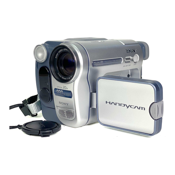
Photo: DCR-TRV280
BLOCK DIAGRAMS
BLOCK DIAGRAMS
FRAME SCHEMATIC DIAGRAMS
FRAME SCHEMATIC DIAGRAMS
SCHEMATIC DIAGRAMS
SCHEMATIC DIAGRAMS
VIDEO CAMERA RECORDER
Sony EMCS Co.
RMT-830
DCR-TRV280
Canadian Model
Argentine Model
DCR-TRV270E
East European Model
DCR-TRV280/
TRV285E
DCR-TRV270E/
TRV285E
North European Model
DCR-TRV285E
Australian Model
Tourist Model
PRINTED WIRING BOARDS
PRINTED WIRING BOARDS
REPAIR PARTS LIST
REPAIR PARTS LIST
Published by DI Technical Support Section
US Model
AEP Model
UK Model
E Model
IX
2004L0500-1
©2004.12
Advertisement
Table of Contents

Related Manuals for Sony HandyCam DCR-TRV270E


Summary of Contents for Sony HandyCam DCR-TRV270E
- Page 1 • TO TAKE OUT A CASSETTE WHEN NOT EJECT (FORCE EJECT) • HELP: Sheet attachment positions and procedures of processing the flexible boards/harnesses are shown. VIDEO CAMERA RECORDER 2004L0500-1 DCR-TRV270E/TRV280/TRV285E ©2004.12 Sony EMCS Co. 9-876-780-12 Published by DI Technical Support Section...
-
Page 2: Specifications
SERIES SPECIFICATIONS AC Adaptor AC-L15A/L15B Input/Output connectors Video camera recorder Audio/Video output Power requirements AV MINIJAC K AC 100 - 240 V, 50/60 Hz Video signal: 1 Vp-p, 75 Ω: (ohms), Current consumption unbalanced, sync negative 0.35 - 0.18 A System Audio signal: 327 mV (at output impedance Power consumption... - Page 3 MARK 0 ON THE SCHEMATIC DIAGRAMS AND IN THE PARTS CRITIQUES POUR LA SÉCURITÉ DE FONCTIONNEMENT. NE LIST ARE CRITICAL TO SAFE OPERATION. REPLACE THESE REMPLACER CES COMPOSANTS QUE PAR DES PIÈSES SONY COMPONENTS WITH SONY PARTS WHOSE PART NUMBERS DONT LES NUMÉROS SONT DONNÉS DANS CE MANUEL OU APPEAR AS SHOWN IN THIS MANUAL OR IN SUPPLEMENTS DANS LES SUPPÉMENTS PUBLIÉS PAR SONY.
-
Page 4: Table Of Contents
TABLE OF CONTENTS Section Title Page Section Title Page SERVICE NOTE REPAIR PARTS LIST 1-1. Note for Repair ································································ 1-1 5-1. Exploded Views ···························································· 5-2 1-2. Power Supply During Repairs ········································· 1-1 5-1-1. Overall Assembly ·························································· 5-2 1-3. To Take Out a Cassette when not Eject (Force Eject) ····· 1-2 5-1-2. -
Page 5: Service Note
1. SERVICE NOTE 1-1. NOTE FOR REPAIR Make sure that the flat cable and flexible board are not cracked of When remove a connector, don’t pull at wire of connector. bent at the terminal. It is possible that a wire is snapped. Do not insert the cable insufficiently nor crookedly. -
Page 6: To Take Out A Cassette When Not Eject (Force Eject)
1-3. TO TAKE OUT A CASSETTE WHEN NOT EJECT (FORCE EJECT) 1 Refer to “SECTION 2. DISASSEMBLY” to remove the mechanism deck block. 2 Disconnect CN2401 (2P) of VC-344 board. 3 Add +5V from the DC POWER SUPPLY and unload with a pressing the cassette compartment. 4 Pull the timing belt in the direction of arrow A with a pincette while pressing the cassette compartment (take care... -
Page 7: Self-Diagnosis Function
1-4. SELF-DIAGNOSIS FUNCTION 1-4-1. Self-diagnosis Function 1-4-2. Self-diagnosis Display When problems occur while the unit is operating, the self-diagnosis When problems occur while the unit is operating, the counter of the function starts working, and displays on the viewfinder or LCD viewfinder or LCD screen shows a 4-digit display consisting of an screen what to do. -
Page 8: Self-Diagnosis Code Table
1-4-4. Self-diagnosis Code Table Self-diagnosis Code Block Detailed Symptom/State Correction Function Code Non-standard battery is used. Use the InfoLITHIUM battery. Condensation. Remove the cassette, and insert it again after one hour. Video head is dirty. Clean with the optional cleaning cassette. LOAD direction. -
Page 9: Disassembly
2. DISASSEMBLY HELP HELP 2-1. FLOW CHART Note: When you remove Cabinet (R) Block, The following flow chart shows the disassembly procedure. or when you assembly, please slide NS knob to the position of "ON". NS knob 0 qa HELP 1 Tripod Screw 0 Tapping (M1.7) x2 2 Tapping (P2) x2... -
Page 10: Mechanism Deck Service Position
2-2. MECHANISM DECK SERVICE POSITION Connection to Check the Mechanism deck To check the mechanism deck, set the Camera or VTR to the "Forced power ON" mode. (Or, connect the control key block (SS-5100) to the CN1009 of VC-344 board and set the power switch to the "CAMERA" or "PLAY/EDIT" mode.) Operate the Camera functions of the zoom and focus, the VTR function using the adjustment remote commander (with the HOLD switch set in the OFF position). -
Page 11: Lcd Service Position
2-3. LCD SERVICE POSITION CPC jig connector Conductor side CN1011 LCD panel Back light unit CPC jig connector (J-6082-539-A) PD-204 board L serices Info LITHIUM battery (7.2Vdc) AC adaptor AC IN AC adaptor AC IN LANC jack Adjustment remote commander (RM-95) I/F unit for LANC control (J-6082-521-A) DCR-TRV270E/TRV280/TRV285E... -
Page 12: Circuit Boards Location
2-4. CIRCUIT BOARDS LOCATION VC-344 CD-471 SI-041 PD-204 Board Name Function CD-471 CCD IMAGER VC-344 A/D CONVERTER, TIMING GENERATOR, DV SIGNAL PROCESS, LENS CONTROL, STEADYSHOT, DV INTERFACE, VIDEO OUT, LENS DRIVE, REC/PB AMP, SERVO, CAMERA/MECHA CONTROL, HI CONTROL, AUDIO PROCESS, DC CONTROL, CONNECTOR PD-204 LCD DRIVE, BACKLIGHT DRIVE SI-041... - Page 13 HELP Sheet attachment positions and procedures of processing the flexible boards/harnesses are shown. Harness (PD-124) Claw Claw Note: Close the LCD panel, when you work. DCR-TRV270E/TRV280/TRV285E HELP...
-
Page 14: Block Diagrams
3. BLOCK DIAGRAMS Link Link OVERALL BLOCK DIAGRAM (1/5) OVERALL BLOCK DIAGRAM (1/5) OVERALL BLOCK DIAGRAM (5/5) OVERALL BLOCK DIAGRAM (5/5) OVERALL BLOCK DIAGRAM (2/5) POWER BLOCK DIAGRAM (1/2) OVERALL BLOCK DIAGRAM (2/5) POWER BLOCK DIAGRAM (1/2) OVERALL BLOCK DIAGRAM (3/5) POWER BLOCK DIAGRAM (2/2) OVERALL BLOCK DIAGRAM (3/5) POWER BLOCK DIAGRAM (2/2) - Page 15 3. BLOCK DIAGRAMS 3-1. OVERALL BLOCK DIAGRAM (1/5) ( ) : Number in parenthesis ( ) indicates the division number of schematic diagram where the component is located. CD-471 BOARD VC-344 BOARD (1/4) LENS ASSY XRST VTR IRIS OVERALL (3/5) CN951 CN1501 Q951...
-
Page 16: Overall Block Diagram (1/5)
3-2. OVERALL BLOCK DIAGRAM (2/5) ( ) : Number in parenthesis ( ) indicates the division number of schematic diagram where the component is located. CN751 SI-041 BOARD (2/3) VC-344 BOARD (2/4) TRV280/ CN1001 CN754 TRV285E TPA+, –, (2/3) (2/3) TPB+, –... -
Page 17: Overall Block Diagram (2/5)
3-3. OVERALL BLOCK DIAGRAM (3/5) ( ) : Number in parenthesis ( ) indicates the division number of schematic diagram where the component is located. VC-344 BOARD (3/4) (5/10) M2000 MECHA DECK (2/2) IC2401 (3/3) (9/10) (5/10) M901 CN2402 DRUM MOTOR XRST VTR OVERALL (1/5) Q1310... -
Page 18: Overall Block Diagram (3/5)
3-4. OVERALL BLOCK DIAGRAM (4/5) ( ) : Number in parenthesis ( ) indicates the division number of schematic diagram where the component is located. VC-344 BOARD (4/4) CN1011 (3/3) LANC IN LANC OUT XLANC POWER ON (FOR CHECK) CONTROL KEY PD-204 BOARD (1/2) BLOCK (SB-9000) CN6006... -
Page 19: Overall Block Diagram (4/5)
3-5. OVERALL BLOCK DIAGRAM (5/5) ( ) : Number in parenthesis ( ) indicates the division number of schematic diagram where the component is located. PD-204 BOARD (2/2) CN6001 LCD901 CN6004 (2/2) PANEL R, PANEL G, PANEL B PANEL R, PANEL G, PANEL B VR, VG, VB ı... -
Page 20: Power Block Diagram (1/2)
3-6. POWER BLOCK DIAGRAM (1/2) ( ) : Number in parenthesis ( ) indicates the division number of schematic diagram where the component is located. VC-344 BOARD (1/2) BT901 BATTERY BATT SIG TERMINAL BATT/XEXT BATT/XEXT CN4001 F002 FAST CHARGE BATT UNREG INIT CHARGE ON BATT SIG Q4003, 4004... -
Page 21: Power Block Diagram (2/2)
3-7. POWER BLOCK DIAGRAM (2/2) ( ) : Number in parenthesis ( ) indicates the division number of schematic diagram where the component is located. VC-344 BOARD (2/2) CONTROL KEY BLOCK (SS-5100) CN1009 D004 CHARGE LED VDD BATT/XEXT BATT/XEXT BATT/EXT FAST CHARGE IC5001 D002... -
Page 22: Printed Wiring Boards And Schematic Diagrams
4. PRINTED WIRING BOARDS AND SCHEMATIC DIAGRAMS 4-1. FRAME SCHEMATIC DIAGRAM FRAME SCHEMATIC DIAGRAM CN951 CD-471 FP-301 FP-302 M2000 MECHANISM DECK FP-794 LENS FLEXIBLE FLEXIBLE FLEXIBLE BOARD EVF BLOCK BLOCK BOARD BOARD (CCD IMAGER) CAM_15V VSHT FP-228 FP-299 FP-802 FLEXIBLE CAM_-7.5V LCD902 FLEXIBLE... -
Page 23: Schematic Diagrams
4-2. SCHEMATIC DIAGRAMS Link Link CD-471 BOARD CD-471 BOARD (CCD IMAGER) VC-344 BOARD (9/10) (CCD IMAGER) VC-344 BOARD (9/10) (DC CONTROL) (DC CONTROL) VC-344 BOARD (1/10) VC-344 BOARD (1/10) VC-344 BOARD (10/10) VC-344 BOARD (10/10) (CONNECTOR) (CONNECTOR) (A/D CONVERTER, TIMING GENERATOR) (A/D CONVERTER, TIMING GENERATOR) VC-344 BOARD (2/10) PD-204 BOARD... - Page 24 4-2. SCHEMATIC DIAGRAMS 4-2. SCHEMATIC DIAGRAMS 4-2. SCHEMATIC DIAGRAMS THIS NOTE IS COMMON FOR SCHEMATIC DIAGRAMS (In addition to this, the necessary note is printed in each block) (For schematic diagrams) 1. Connection • All capacitors are in µF unless otherwise noted. pF : µ Pattern box µF.
- Page 25 For Schematic Diagram • Refer to page 4-41 for printed wiring board. Note: IC951 is not included in CD-471 BOARD CD-471 complete board. LND951 CCD IMAGER C954 XX MARK:NO MOUNT NO MARK:REC/PB MODE R:REC MODE P:PB MODE CN951 IC951 CCD IMAGER IC951 ICX219CKA-43: TRV280...
- Page 26 For Schematic Diagram • Refer to page 4-43 for printed wiring board. VC-344 BOARD (1/10) AD CONVERTER, TIMING GENERATOR (CAM BLOCK) XX MARK:NO MOUNT NO MARK:REC/PB MODE R:REC MODE CAM_-7.5V P:PB MODE CAM_15V *:IMPOSSIBLE TO MEASURE THE VOLTAGE AT THE MARKED POINTS. A_2.8V D_2.8V (9/10)
- Page 27 For Schematic Diagram • Refer to page 4-43 for printed wiring board. VC-344 BOARD (2/10) DV SIGNAL PROCESS, LENS CONTROL, STEADYSHOT, DV INTERFACE, VIDEO OUT (JC BLOCK, IO BLOCK) XX MARK:NO MOUNT NO MARK:REC/PB MODE R:REC MODE P:PB MODE D_1.5V D_1.9V A_2.8V C3357...
- Page 28 For Schematic Diagram • Refer to page 4-43 for printed wiring board. VC-344 BOARD (3/10) LENS DRIVE (LD BLOCK, EVR BLOCK) FB1601 XX MARK:NO MOUNT NO MARK:REC/PB MODE AU_2.8V R:REC MODE D_2.8V P:PB MODE R1560 C1601 4.7u R1567 R1568 L1553 CAM_SO 2200 6800...
- Page 29 For Schematic Diagram • Refer to page 4-43 for printed wiring board. VC-344 BOARD (4/10) REC/PB AMP (RF BLOCK) C3220 100p RB3202 Q3204 2200 2SA207800LS0 XX MARK:NO MOUNT L3203 NO MARK:REC/PB MODE 220uH R3220 C3222 R:REC MODE L3204 R3225 R3230 RB3201 12uH P:PB MODE...
- Page 30 For Schematic Diagram • Refer to page 4-43 for printed wiring board. VC-344 BOARD (5/10) XX MARK:NO MOUNT NO MARK:REC/PB MODE R:REC MODE SERVO (MD DRIVE BLOCK) P:PB MODE *:IMPOSSIBLE TO MEASURE THE VOLTAGE AT THE MARKED POINTS. EP_13.5V VTR_UNREG D_2.8V REG_GND (MT_GND)
- Page 31 For Schematic Diagram • Refer to page 4-43 for printed wiring board. FB4501 VC-344 BOARD (6/10) D_1.9V D_2.8V CAMERA/MECHA CONTROL (VC BLOCK) (9/10) REG_GND XX MARK:NO MOUNT NO MARK:REC/PB MODE R:REC MODE IC4502 P:PB MODE *:IMPOSSIBLE TO MEASURE THE EEPROM RB4514 IC4502 100k...
- Page 32 For Schematic Diagram • Refer to page 4-43 for printed wiring board. VC-344 BOARD (7/10) HI CONTROL (HI BLOCK) XX MARK:NO MOUNT NO MARK:REC/PB MODE R:REC MODE P:PB MODE VOUT D_2.8V BATT_UNREG EVER_3.0V XCS_DD Q5001 R5017 VTR_UNREG XCS_DD HN1L02FU(TE85R) (9/10) HI_EVER_SO ±0.5% BATTERY CHARGE...
- Page 33 For Schematic Diagram • Refer to page 4-43 for printed wiring board. VC-344 BOARD (8/10) AUDIO PROCESS (AU BLOCK) C5439 XX MARK:NO MOUNT 0.001u REG_GND(MIC_GND) NO MARK:REC/PB MODE C5441 R5429 0.001u 1500 INT_MIC_L R5432 C5437 0.01u SFD_BCK INT_MIC_R (10/10) R5431 R5430 C5438 SFD_FCK...
- Page 34 For Schematic Diagram • Refer to page 4-43 for printed wiring board. VC-344 BOARD (9/10) L1309 4.7uH L1305 DC CONTROL (DD BLOCK, FU BLOCK) C1340 22uH 6.3V XX MARK:NO MOUNT Q1305 L1312 CPH5815-TL-E 4.7uH SWITCHING NO MARK:REC/PB MODE C1330 4.7u R:REC MODE L1313 4.7uH...
- Page 35 For Schematic Diagram • Refer to page 4-43 for printed wiring board. REG_GND (BL_GND) VC-344 BOARD (10/10) BL_REG BL_CONT (9/10) CONNECTOR (SE BLOCK, CN BLOCK) XX MARK:NO MOUNT R1003 CN1003 NO MARK:REC/PB MODE EVF BLOCK PANEL_13.5V CN1013 PANEL_4.6V 3.3V PANEL_2.8V EVF_DD_ON ZOOM_VR_AD LCD902...
- Page 36 For Schematic Diagram • Refer to page 4-47 for printed wiring board. PD-204 BOARD LCD DRIVER, BACKLIGHT DRIVE XX MARK:NO MOUNT NO MARK:REC/PB MODE CN6001 FB6002 PANEL_13.5V PANEL_4.6V PANEL_2.8V FB6001 PANEL_-15.3V L6001 REG_GND 47uH PANEL_HOLD PANEL_HOLD C6020 C6019 C6002 3.3u VC-344 VD_SI(HDO) (10/10)
-
Page 37: Jack
For Schematic Diagram • Refer to page 4-49 for printed wiring board. FP-792 FLEXIBLE BOARD VIDEO LIGHT Note: D001, D002 and D003 are not included in FP-792 flexible board. D002 NSPW500BS-TL2 REG_GND D001 D003 D001-003 NSPW500BS-TL2 NSPW500BS-TL2 (VIDEO LIGHT) LAND1 STATIC_GND REG_GND STATIC_GND... -
Page 38: Flexible
For Schematic Diagram • Refer to page 4-51 for printed wiring board. CONTROL KEY BLOCK FP-302 (SS-5100) FLEXIBLE FP-802 FLEXIBLE XX MARK:NO MOUNT BOARD CONTROL KEY BLOCK (SS-5100) is replaced as block, FP-300 BOARD so that PRINTED WIRING BOARD is omitted. VC-344 FLEXIBLE Q002... - Page 39 CONTROL KEY BLOCK (CF-5100) is replaced as block, CONTROL KEY BLOCK (CF-5100) so that PRINTED WIRING BOARD is omitted. XX MARK:NO MOUNT S012 S015 S003 S007 STOP PLAY S022 S023 R013 R020 R005 R009 R017 R022 EASY (PANEL_O/C_SW) 1200 2200 3900 8200 1500...
-
Page 40: Flexible
4-3. PRINTED WIRING BOARDS Link Link CD-471 BOARD CD-471 BOARD SI-041 BOARD SI-041 BOARD VC-344 BOARD (SIDE A) VC-344 BOARD (SIDE A) FP-792 FLEXIBLE BOARD FP-792 FLEXIBLE BOARD FP-228, FP-299, FP-300, FP-301, FP-302, FP-228, FP-299, FP-300, FP-301, FP-302, VC-344 BOARD (SIDE B) VC-344 BOARD (SIDE B) FP-802 FLEXIBLE BOARD FP-802 FLEXIBLE BOARD... - Page 41 4-3. PRINTED WIRING BOARDS 4-3. PRINTED WIRING BOARDS 4-3. PRINTED WIRING BOARDS THIS NOTE IS COMMON FOR PRINTED WIRING BOARDS • : Uses unleaded solder. • Chip parts. • : Circuit board Transistor Diode : Flexible board Pattern from the side which enables seeing. : pattern of the rear side (The other layers’...
- Page 42 CD-471 Note for Printed Wiring Board (See page 4-39). : Uses unleaded solder. CD-471 BOARD L951 C953 R952 C952 C954 Q951 R969 D951 R968 Note: IC951 is not included in CD-471 complete board. LND951 IC951 C955 1-860-935- DCR-TRV270E/TRV280/TRV285E CD-471 4-41 4-42...
- Page 43 Ver 1.1 2004. 12 VC-344 Note for Printed Wiring Board (See page 4-39). : Uses unleaded solder. VC-344 BOARD (SIDE A) CN2403 CN3201 R2402 CN2402 R3221 R3222 R3223 R3224 R2401 C3217 R3219 R3218 R3216 C2428 R2443 R3214 C2438 R3212 IC3201 C2433 C3214 C3215...
- Page 44 Note for Printed Wiring Board (See page 4-39). : Uses unleaded solder. VC-344 BOARD (SIDE B) Q3204 C3223 RB3202 C2403 CN2404 R2405 C2409 R3230 C2406 C3222 C2407 R3225 R2404 C2402 C2441 R2419 R3231 C3220 C2414 C3221 R2431 C2443 R2434 C2444 R1529 R2437 R1530...
- Page 45 PD-204 Note for Printed Wiring Board (See page 4-39). : Uses unleaded solder. PD-204 BOARD L6002 C6007 D6007 C6019 C6011 LND605 Q6002 Note: Q6002 and Q6003 have the same mount location. CL6017 CL6016 C6020 When you replace, since either Q6002 or Q6003 CL6012 Q6003 is used, please refer to schematic diagram and...
- Page 46 SI-041, FP-792 FLEXIBLE Note for Printed Wiring Board (See page 4-39). D001 D002 : Uses unleaded solder. (VIDEO LIGHT) (VIDEO LIGHT) Note: D001, D002 and D003 are not included in FP-792 flexible board. FP-792 FLEXIBLE BOARD FP-792 1-860- 929- 1-860-929- D003 (VIDEO LIGHT) Note: CN751, CN752, D753, D754, IC751 and J752 are...
- Page 47 FP-228, FP-299, FP-300, FP-301, FP-302, FP-802 FLEXIBLE Note for Printed Wiring Board (See page 4-39). : Uses unleaded solder. FP-300 FLEXIBLE BOARD (COMPONENT SIDE) Q001 TAPE TOP 1-680-436- SENSOR FP-299 FLEXIBLE FP-802 FLEXIBLE BOARD BOARD S002 (CONDUCTOR SIDE) C.C. LOCK M902 D001 CAPSTAN...
-
Page 48: Waveforms
CD-471 BOARD CD-471 BOARD 4-4. WAVEFORMS CD-471 BOARD 3.6 Vp-p 7.6 Vp-p IC951 1 REC IC951 qf REC 22 Vp-p 3.6 Vp-p IC951 2 REC IC951 qd REC 2.4 Vp-p 7.6 Vp-p 13.5 MHz IC951 3 REC IC951 qs REC 22 Vp-p 22 Vp-p IC951 q;... - Page 49 VC-344 BOARD SIDE A VC-344 BOARD SIDE B VC-344 BOARD SIDE A VC-344 BOARD SIDE B VC-344 BOARD (1/3) 1.7 Vp-p 2.9 Vp-p 27 MHz 13.5 MHz IC1501 5 (X1501) REC/PB IC3301 <zvz REC/PB 3.0 Vp-p 2.8 Vp-p 13.5 MHz IC1501 qs REC/PB IC3301 <zcz REC/PB 2.8 Vp-p...
- Page 50 VC-344 BOARD SIDE A VC-344 BOARD SIDE B VC-344 BOARD SIDE A VC-344 BOARD SIDE B VC-344 BOARD (2/3) 440 mVp-p 540 mVp-p 13.3 msec IC3201 eg PB IC3301 <zz. REC/PB 330 mVp-p 2.8 Vp-p 13.3 msec IC3301 <zzn REC/PB IC3201 ek REC/PB 1.0 Vp-p 170 mVp-p...
- Page 51 VC-344 BOARD SIDE A VC-344 BOARD SIDE B VC-344 BOARD SIDE A VC-344 BOARD SIDE B VC-344 BOARD (3/3) 3.2 Vp-p 1.8 Vp-p 450 Hz 20 MHz IC2401 yd, yg, yk REC/PB IC4501 1 (X4501) REC/PB 2.8 Vp-p 3.0 Vp-p 450 Hz 32.768 kHz IC5001 ta (X5002) REC/PB...
- Page 52 PD-204 BOARD PD-204 BOARD PD-204 BOARD 460 mVp-p 5.9 Vp-p IC6001 ek REC/PB IC6001 wg REC/PB 470 mVp-p 3.5 Vp-p IC6001 el REC/PB IC6001 wa REC/PB 470 mVp-p 3.5 Vp-p IC6001 r; REC/PB IC6001 w; REC/PB 2.8 Vp-p 3.5 Vp-p IC6001 rs REC/PB IC6001 ql REC/PB 2.8 Vp-p...
-
Page 53: Mounted Parts Location
4-3. PRINTED WIRING BOARDS 4-3. PRINTED WIRING BOARDS 4-5. MOUNTED PARTS LOCATION no mark : side A * mark : side B VC-344 BOARD C1003 * C1566 C4004 * D1302 D-8 * Q1304 E-8 R1338 C-9 * C1301 * C1568 C4005 * D1303 F-8 * Q1305 F-7... - Page 54 4-3. PRINTED WIRING BOARDS 4-3. PRINTED WIRING BOARDS no mark : side A * mark : side B PD-204 BOARD SI-041 BOARD R4001 F-9 * X1501 C6001 * CN751 B-1 R4003 F-8 X4501 C6002 * CN752 C-1 R4004 G-8 X5001 C6003 * CN753 D-4 * R4006 F-8...
-
Page 55: Repair Parts List
NOTE NOTE 5. REPAIR PARTS LIST NOTE: Characters A to L of the electrical parts list indicate location of exploded views in which the desired part is shown. EXPLODED VIEWS EXPLODED VIEWS Link Link OVERALL ASSEMBLY FRONT PANEL BLOCK LENS BLOCK LCD BLOCK OVERALL ASSEMBLY FRONT PANEL BLOCK... - Page 56 5. REPAIR PARTS LIST 5. REPAIR PARTS LIST 5. REPAIR PARTS LIST NOTE: • -XX, -X mean standardized parts, so they may have some differences from When indicating parts by reference number, the original one. please include the board name. •...
- Page 57 5. REPAIR PARTS LIST 5. REPAIR PARTS LIST 5-1. EXPLODED VIEWS 5-1-1. OVERALL ASSEMBLY ns: not supplied EVF block (See page 5-7.) MD frame block Battery panel block (See page 5-9.) (SIZE: (See page 5-8.) 1.5cm X 3.5cm) Cabinet R block (See page 5-6.) Front panel block (See page 5-3.)
- Page 58 5. REPAIR PARTS LIST 5. REPAIR PARTS LIST 5-1-2. FRONT PANEL BLOCK ns: not supplied D001 D002 D003 J752 CN751 D753 D754 CN752 S I - IC751 Note1: CN751, CN752, D753, D754, IC751 and J752 are not MIC901 included in SI-041 complete board. Note2: D001, D002 and D003 are not included in FP-792 flexible board.
-
Page 59: Lens Block
Ver 1.1 2004. 12 5. REPAIR PARTS LIST 5. REPAIR PARTS LIST 5-1-3. LENS BLOCK - 4 7 IC951 (Note1, 2) Note1: IC951 is not included in CD-471 complete board. Note2: Be sure to read “Precuations for Replacement of CCD Imager”... -
Page 60: Lcd Block
5. REPAIR PARTS LIST 5. REPAIR PARTS LIST 5-1-4. LCD BLOCK LCD901 ND901 - 2 0 The components identified by Les composants identifiés par une mark 0 or dotted line with marque 0 sont critiques pour la mark 0 are critical for safety. sécurité. -
Page 61: Cabinet R Block
5. REPAIR PARTS LIST 5. REPAIR PARTS LIST 5-1-5. CABINET R BLOCK ns: not supplied (including BT001) (BT001) : BT001 (BATTERY, LITHIUM SECONDARY) Included in the control switch block (CF-5100). CAUTION Danger of explosion if battery is incorrectly replaced. Replace only with the same or equivalent type. Ref. -
Page 62: Evf Block
5. REPAIR PARTS LIST 5. REPAIR PARTS LIST 5-1-6. EVF BLOCK ns: not supplied LCD902 Ref. No. Part No. Description Ref. No. Part No. Description X-2025-532-1 CABINET (UPPER (955)) ASSY, EVF 3-080-203-31 SCREW (M2), LOCK ACE, P2 X-3951-166-1 LENS (M) ASSY, VF 1-860-928-12 FP-797 FLEXIBLE BOARD X-2025-533-1 CABINET (LOWER (905)) ASSY, EVF LCD902 1-805-465-61 INDICATOR MODULE LIQUID CRYSTAL... -
Page 63: Battery Panel Block
Ver 1.1 2004. 12 5. REPAIR PARTS LIST 5. REPAIR PARTS LIST 5-1-7. BATTERY PANEL BLOCK ns: not supplied BT901 Ref. No. Part No. Description Ref. No. Part No. Description 3-087-799-01 SHEET METAL (LOWER) (51), STRAP 3-072-305-11 LID (2500), JACK 3-078-889-11 SCREW (M1.7) BT901 1-694-772-11 TERMINAL BOARD, BATTERY... -
Page 64: Md Frame Block
5. REPAIR PARTS LIST 5. REPAIR PARTS LIST 5-1-8. MD FRAME BLOCK ns: not supplied - 3 4 Mechanism deck block (See page 5-10 to 5-13.) Ref. No. Part No. Description Ref. No. Part No. Description 1-478-417-31 KEY BLOCK, CONTROL (SS-5100) 3-089-368-01 LABEL, FUSE REPLACEMENT (51) (TRV280) 3-080-253-01 SCREW (M1.7), LOCK ACE, P2 X-2048-472-1 CABINET (L (910)) ASSY... -
Page 65: Cassette Compartment Assembly, Drum Assembly
5. REPAIR PARTS LIST 5. REPAIR PARTS LIST 5-1-9. CASSETTE COMPARTMENT ASSEMBLY, DRUM ASSEMBLY ns: not supplied LS chassis block assembly M901 (See page 5-11.) Mechanical chassis block assembly (See page 5-12 to 5-13.) Ref. No. Part No. Description Ref. No. Part No. -
Page 66: Ls Chassis Block Assembly
5. REPAIR PARTS LIST 5. REPAIR PARTS LIST 5-1-10. LS CHASSIS BLOCK ASSEMBLY S001 ns: not supplied S002 Q001 H001 FP-802 H002 Q002 FP-301 D001 FP-302 FP-300 Ref. No. Part No. Description Ref. No. Part No. Description 3-065-822-02 RAIL (S), GUIDE 3-065-830-01 SPRING, S RATCHET 3-947-503-01 SCREW (M1.4) X-3951-288-1 TABLE (T) ASSY, REEL... -
Page 67: Mechanical Chassis Block Assembly-1
5. REPAIR PARTS LIST 5. REPAIR PARTS LIST 5-1-11. MECHANICAL CHASSIS BLOCK ASSEMBLY-1 ns: not supplied S901 M902 M903 Mechanical chassis block assembly-2 (See page 5-13.) Ref. No. Part No. Description Ref. No. Part No. Description A-7096-422-A BASE ASSY, DRUM 3-065-881-01 SPRING, P PRESSURE PLATE 3-947-503-01 SCREW (M1.4) 3-065-934-01 HLW CUT 0.98X3X0.25... -
Page 68: Mechanical Chassis Block Assembly-2
5. REPAIR PARTS LIST 5. REPAIR PARTS LIST 5-1-12. MECHANICAL CHASSIS BLOCK ASSEMBLY-2 Ref. No. Part No. Description Ref. No. Part No. Description 3-065-920-01 ARM, HC DRIVE 7-624-101-04 STOP RING 1.2 (E TYPE) 3-065-913-01 GEAR (4), LD A-7096-412-A GEAR (T) ASSY, GUIDE 3-065-914-01 SHEET, COVER X-3951-307-1 PLATE ASSY, M SLIDE 3-065-917-01 GEAR (1), CAM RELAY... -
Page 69: Electrical Parts List
CD-471 FP-228 FP-299 FP-300 FP-301 FP-302 FP-792 FP-802 PD-204 5-2. ELECTRICAL PARTS LIST Ref. No. Part No. Description Ref. No. Part No. Description A-7111-947-A CD-471 BOARD, COMPLETE (Not supplied) FP-301 FLEXIBLE BOARD (Note2) *********************** ******************** (IC951 is not included in this complete board.) <... - Page 70 PD-204 SI-041 VC-344 Ref. No. Part No. Description Ref. No. Part No. Description C6026 1-119-750-11 TANTAL. CHIP 22uF 6.3V < TRANSFORMER > C6027 1-125-777-11 CERAMIC CHIP 0.1uF 0 T6001 1-435-786-31 TRANSFORMER, INVERTER C6028 1-115-407-11 ELECT CHIP 10uF C6029 1-125-827-91 CERAMIC CHIP A-1082-751-A SI-041 BOARD, COMPLETE <...
- Page 71 VC-344 Ref. No. Part No. Description Ref. No. Part No. Description C1310 1-164-938-11 CERAMIC CHIP 0.0015uF 10% C1515 1-115-467-11 CERAMIC CHIP 0.22uF C1516 1-162-970-11 CERAMIC CHIP 0.01uF C1311 1-125-777-11 CERAMIC CHIP 0.1uF C1518 1-125-837-91 CERAMIC CHIP 6.3V C1312 1-125-837-91 CERAMIC CHIP 6.3V C1523 1-107-826-11 CERAMIC CHIP...
- Page 72 VC-344 Ref. No. Part No. Description Ref. No. Part No. Description C2442 1-125-777-11 CERAMIC CHIP 0.1uF C4510 1-125-777-11 CERAMIC CHIP 0.1uF C4511 1-125-777-11 CERAMIC CHIP 0.1uF C3201 1-127-760-11 CERAMIC CHIP 4.7uF 6.3V C4512 1-125-777-11 CERAMIC CHIP 0.1uF C3202 1-164-943-11 CERAMIC CHIP 0.01uF C4514 1-125-837-91 CERAMIC CHIP...
- Page 73 VC-344 Ref. No. Part No. Description Ref. No. Part No. Description IC1552 8-759-681-42 IC NJM12902V (TE2) < CONNECTOR > IC1553 8-759-637-96 IC uPD16877MA-6A5-E2 IC1554 8-759-693-13 IC NJM12904V (TE2) CN1001 1-818-076-11 CONNECTOR, FFC/FPC (ZIF) 36P IC1601 6-706-663-01 IC NJW5210RB1 CN1003 1-794-998-31 PIN, CONNECTOR 20P IC2401 6-705-676-01 IC TB6550FG (O, EB) CN1007 1-779-335-21 CONNECTOR, FFC/FPC 22P...
- Page 74 VC-344 Ref. No. Part No. Description Ref. No. Part No. Description Q1305 6-550-405-01 TRANSISTOR CPH5815-TL-E R1306 1-218-961-11 RES-CHIP 4.7K 1/16W Q1306 6-550-405-01 TRANSISTOR CPH5815-TL-E R1307 1-218-970-11 RES-CHIP 1/16W Q1307 6-550-405-01 TRANSISTOR CPH5815-TL-E Q1308 6-550-405-01 TRANSISTOR CPH5815-TL-E R1308 1-218-971-11 RES-CHIP 1/16W R1309 1-218-963-11 RES-CHIP 6.8K...
- Page 75 VC-344 Ref. No. Part No. Description Ref. No. Part No. Description R1573 1-218-947-11 RES-CHIP 1/16W R4003 1-216-864-11 SHORT CHIP R1575 1-218-953-11 RES-CHIP 1/16W R4004 1-216-864-11 SHORT CHIP R1576 1-218-965-11 RES-CHIP 1/16W R1577 1-218-973-11 RES-CHIP 1/16W R4006 1-218-977-11 RES-CHIP 100K 1/16W R1581 1-208-715-11 METAL CHIP 0.5%...
- Page 76 VC-344 Ref. No. Part No. Description Ref. No. Part No. Description RB4501 1-234-381-21 RES, NETWORK 100K (1005 x4) RB4508 1-234-378-21 RES, NETWORK 10K (1005 x4) RB4509 1-234-381-21 RES, NETWORK 100K (1005 x4) RB4510 1-234-381-21 RES, NETWORK 100K (1005 x4) RB4511 1-234-375-21 RES, NETWORK 1K (1005 x4) RB4512 1-234-384-11 RES, NETWORK 1M (1005 x4) RB4514 1-234-381-21 RES, NETWORK 100K (1005 x4) RB4515 1-234-375-21 RES, NETWORK 1K (1005 x4)
-
Page 77: Checking Supplied Accessories
Checking supplied accessories. Power cord (1) 0 1-696-819-22 (AUS) AC-L15A/L15B AC Adaptor (1) 0 1-769-608-11 (AEP, NE, EE, E) Rechargeable battery pack 0 1-477-533-51 0 1-783-374-11 (UK) NP-FM30 (1) 0 1-783-952-21 (AR) 0 A-7096-387-A (US, CND) 0 1-790-542-12 (US, CND) 0 A-7096-388-B 0 1-827-160-11 (JE) (EXCEPT US, CND) - Page 78 [Description of main button functions on toolbar of the Adobe Acrobat Reader Ver5.0 (for Windows)] Toolbar Printing a text Reversing the screens displayed once • To reverse the previous screens (operation) one by one, click 1. Click the Print button 2.
-
Page 79: Revision History
Reverse 987678012.pdf Revision History S.M. Rev. Ver. Date History Contents issued 2004.11 Official Release — — 2004.12 Revised-1 • Correction of Printed Wiring Board • Correction of Repair Parts List S.M. correction: Page 4-44, Page 5-4, Page 5-8 DCR-TRV270E/TRV280/TRV285E...
Need help?
Do you have a question about the HandyCam DCR-TRV270E and is the answer not in the manual?
Questions and answers