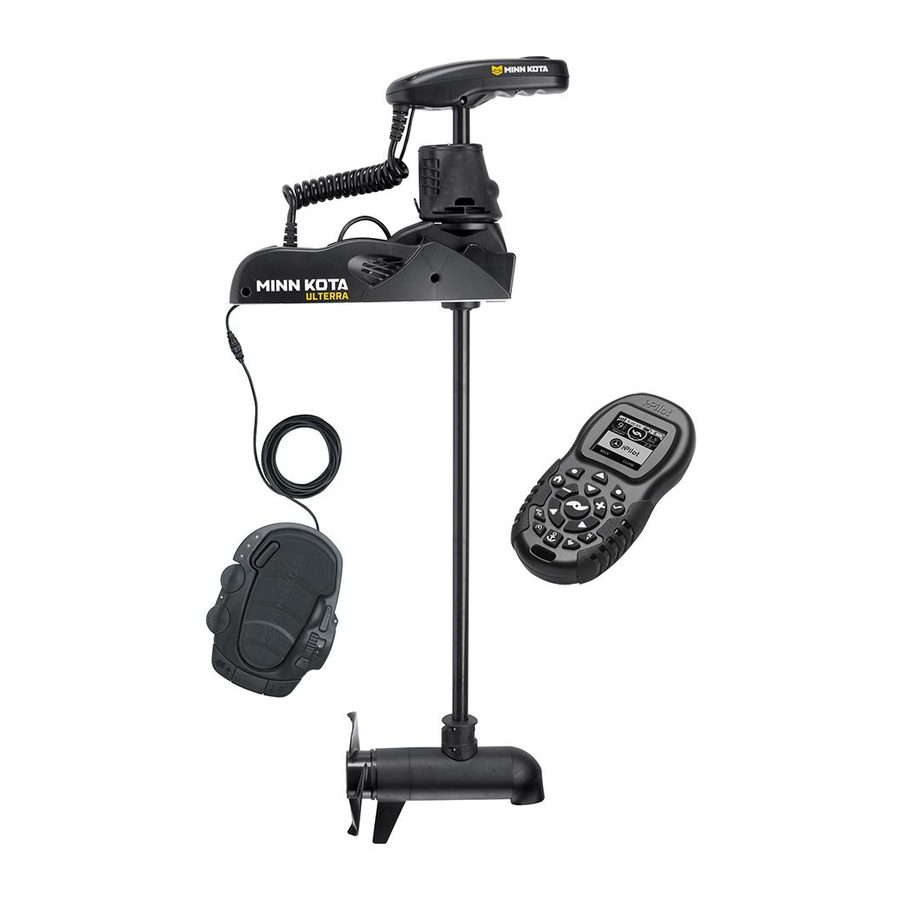
MINN KOTA ULTERRA Owner's Manual
With i-pilot bow-mount trolling motor
Hide thumbs
Also See for ULTERRA:
- User manual ,
- Owner's manual (98 pages) ,
- Installation instructions manual (84 pages)
Table of Contents
Advertisement
Advertisement
Table of Contents
Troubleshooting

Related Manuals for MINN KOTA ULTERRA


Summary of Contents for MINN KOTA ULTERRA
- Page 1 ULTERRA™ WITH i-PILOT ® BOW-MOUNT TROLLING MOTOR OWNER'S MANUAL...
-
Page 2: Introduction
2,5m/sec2. You are responsible for the safe and prudent operation of your vessel. We have designed Ulterra to be an accurate and reliable tool that will enhance boat operation and improve your ability to catch ish. This product does not relieve you from the responsibility for safe operation of your boat. You must avoid hazards to navigation and always maintain a permanent watch so you can respond to situations as they develop. -
Page 3: Table Of Contents
TAbLE Of COnTEnTs Introduction Two-Year Limited Warranty Warranty on Minn Kota i-Pilot® and i-Pilot® Link™ Wireless GPS Trolling System Warranty on Minn Kota Freshwater Trolling Motors Features Motor Features Control Panel Features i-Pilot Remote Features Foot Pedal Features 8-11 Mount Installation 12-13 Battery &... -
Page 4: Two-Year Limited Warranty
KOTA LImITEd TWO-YEAR WARRAnTY On THE EnTIRE PROdUCT JOME warrants to the original retail purchaser only that the purchaser’s new Minn Kota i-Pilot® or i-Pilot® Link™ Wireless GPS Trolling System Accessory will be materially free from defects in materials and workmanship appearing within two (2) years after the date of purchase. JOME will (at its option) either repair or replace, free of charge, any parts found by JOME to be defective during the term of this warranty. -
Page 5: Warranty On Minn Kota Freshwater Trolling Motors
KOTA LImITEd LIfETImE WARRAnTY On COmPOsITE sHAfT JOME warrants to the original retail purchaser only that the composite shaft of the purchaser’s Minn Kota trolling motor will be materially free from defects in materials and workmanship appearing within the original purchaser’s lifetime. JOME will provide a new composite shaft, free of charge, to replace any composite shaft found by JOME to be defective during the term of this warranty. -
Page 6: Features
fEATUREs mOTOR fEATUREs Integrated i-Pilot Control Head Power Trim Power Stow/Deploy Lifetime Warranty Flexible Composite Shaft Multi-Function Footpedal Cool Quiet Power Motor Weedless Wedge 2 Propeller Speciications subject to change without notice. *This diagram is for reference only and may difer from your actual motor. 6 | minnkotamotors.com ©2014 Johnson Outdoors Marine Electronics, Inc. -
Page 7: Control Panel Features
fEATUREs COnTROL PAnEL Power Button: Press the power button to turn the motor on or of . Once power button is pressed, power will remain on for 1.5 hours in the absence of any button presses, when motor is stowed. Press and hold for two seconds to turn motor of . Status (red LED): The motor is equipped with a status indicator. -
Page 8: Mount Installation
A RTs InCLUdEd ✒ Your new Ulterra comes out of the box with everything you’ll need for direct to boat mounting. This motor can be direct mounted to the boat or coupled with a Minn Kota quick release bracket for ease of mounting and removal. - Page 9 InsTALLATIOn Parts Included: Description Qty. Screw, 1/4-20 x 2” HH Screw, 1/4-20 x 0.5 HH Washer-Clipped, 1/4”, 1” OD Nut, 1/4-20 Nylock SS Washer, 1/4” Flat 18-8 SS Washer-Mounting, Rubber Tools and Resources Required: • Drill • 5/16” Drill Bit •...
- Page 10 InsTALLATIOn 5. Mount the motor to the boat using the provided hardware. Install the hex head bolts and clipped washers on the right side of the motor as viewed from the boat interior. (Figure 5) Motor can then be slid into place utilizing the slots on the motor base plate.
-
Page 11: Mounting Options
Turn power on and deploy motor using the stow/deploy button on footpedal or remote (see the Manual Control section or Ulterra Functions for deploying instructions). CAUTION: When deploying, ensure the motor doesn’t contact boat or trailer. -
Page 12: Battery & Wiring Installation
CAUTION: These guidelines apply to general rigging to support your Minn Kota motor. Powering multiple motors or additional electrical devices from the same power circuit may impact the recommended conductor gauge and circuit breaker size. If you are using wire longer than that provided with your unit, follow the conductor gauge and circuit breaker sizing table below. -
Page 13: Selecting The Correct Batteries
Breaker Sizing Table” in the previous section to i nd the appropriate circuit breaker or fuse for your motor. For motors requiring a 60-amp breaker, the Minn Kota MKR-19 60-amp circuit breaker is recommended. COnnECTIng THE bATTERIEs In sERIEs (If REQUIREd fOR YOUR mOTOR) -
Page 14: Motor Wiring Diagram
Accessory Trim Module Coil Cord Cam Sensor Tilt Sensor Plunger Sensor Power On Button AutoPilot (Red) Spot-Lock (Blue) Status (Red) Ulterra Mode (Amber) Constant (Green) Power (Green) Mode Sensor Spot-Lock Sensor Speed Adjustment Foot Pedal Motor Tilt Motor Steering Module... -
Page 15: Getting Started
gETTIng sTARTEd KnOWIng YOUR REmOTE LAYOUT The i-Pilot remote is divided into four sections: Manual Control, Tracks, Spot-Lock, and Cruise Control/AutoPilot. Buttons in the Manual Control section of the remote do not require a GPS signal to operate and give you full, immediate control over steering, speed and prop functions similar to a CoPilot. - Page 16 gETTIng sTARTEd TRACKs mAnUAL COnTROL Track to End Navigates to the nearest location Steer Left on a previously recorded track and follows it to its end. Track to Start Navigates to the nearest location Steer Right on a previously recorded track and follows it to its start.
-
Page 17: Knowing Your I-Pilot Controller
gETTIng sTARTEd REmOTE bATTERY REPLACEmEnT 1. Make sure hands are clean, dry and static free. Discharge any static electricity by touching a metal object that is grounded. NOTE: Static electricity can damage the circuit board. 2. With the remote upside down, use a large coin to rotate the battery door counterclockwise until either of the Unlock icons align with the arrow FIGURE A (see Figure B). - Page 18 gETTIng sTARTEd AUdIO mOdEs The i-Pilot Controller also contains an internal speaker which can be programmed to work in two dif erent audio modes. The speaker is programmed to operate in audio mode one from the factory. To enable dif erent audio modes hold down at the same time for three seconds.
-
Page 19: System Startup
gETTIng sTARTEd POWER The i-Pilot controller will turn on whenever the trolling motor has power connected and has been turned on. This is when the green system ready light is on. ACCURACY The accuracy and responsiveness with which i-Pilot controls your boat is highly dependent upon many variables. Just a few of these variables and their general ef ects on responsiveness and accuracy are given below so that the behavior of the system can be understood. -
Page 20: Manual Control
nUAL COnTROL mAnUAL COnTROL fUnCTIOnALITY This section describes all Manual Control functions of i-Pilot. A manual function is one in which the operator takes full control of the function such as manually steering the motor in a desired direction or manually adjusting the prop speed to the desired setting, trimming, stowing and deploying, or manually adjusting the prop speed. - Page 21 n UAL COnTROL ✟ ✚ TRImmIng UP And dOWn There will be times when you will need to move your motor up or down depending on how your boat is responding. You can trim up to avoid hitting underwater objects and you can trim down if your prop is coming out of the water. Trim the motor up or down with the i-Pilot remote by pressing NOTE: The prop will temporarily stop while trimming the motor and resume once trimming is stopped.
-
Page 22: Gps Motor Control
gPs mOTOR COnTROL sECTIOn TITLE UndERsTAndIng HOW THE i-PILOT sYsTEm WORKs nAVIgATIOn i-Pilot uses GPS satellite signals as well as digital compass data to know where it is, where it is heading and the direction the motor is pointing. Since i-Pilot depends on GPS satellite signals for navigation, a minimum GPS signal level of one bar is required in order for GPS navigation controls to be enabled. -
Page 23: Spot-Lock
sECTIOn TITLE sPOT-LOCK HOW sPOT-LOCK WORKs sPOT-LOCK Spot-Lock uses a single point as a reference for the spot you want to stay on. This point is recorded and stored into one of the six memory locations when the Spot-Lock button is pushed. Around the Spot-Lock location i-Pilot uses an arrival circle to determine prop speed and direction. - Page 24 sPOT-LOCK EngAgIng sPOT-LOCK 1. Press on the remote. 2. The Memory Location icon will fl ash on the remote LCD for three seconds, allowing you to choose a memory location by pressing . Pressing again or waiting for three seconds accepts the memory location.
-
Page 25: Cruise Control
CRUIsE COnTROL sECTIOn TITLE HOW CRUIsE COnTROL WORKs CRUIsE COnTROL i-Pilot automatically controls the motor speed to maintain a constant GPS speed. EngAgIng CRUIsE COnTROL 1. Press on the remote. 2. The current GPS speed will fl ash, displaying your current speed as the target GPS speed on the remote LCD for three seconds. -
Page 26: Autopilot/Advanced Autopilot
sECTIOn TITLE AUTOPILOT HOW AUTOPILOT WORKs Two dif erent versions of AutoPilot are available: AutoPilot and Advanced AutoPilot. There are distinct dif erences between the two AutoPilots and how they control your boat. AUTOPILOT AutoPilot uses an internal compass to provide heading lock. When AutoPilot is on, it keeps the motor pointed in the same compass direction. -
Page 27: Autopilot/Advanced Autopilot
AUTOPILOT EngAgIng AdVAnCEd AUTOPILOT And AUTOPILOT 1. To engage Advanced AutoPilot, press once. To engage AutoPilot, press and hold for two seconds. 2. The Advanced AutoPilot or AutoPilot icon will be displayed on the remote LCD. Advanced AutoPilot 3. To adjust desired heading, manually steer motor to new heading. i-Pilot will lock onto new heading. dIsEngAgIng AdVAnCEd AUTOPILOT And AUTOPILOT Pressing will disengage AutoPilot. - Page 28 TRACK RECORdIng / PLAYbACK sECTIOn TITLE HOW TRACK RECORdIng And PLAYbACK WORK TRACK RECORdIng And PLAYbACK When the Track Record button is pressed, i-Pilot starts to record GPS position data in the form of track points. The distance between these points varies based on the speed of the boat and the GPS signal strength.
-
Page 29: Track Recording/Playback
TRACK RECORdIng / PLAYbACK RECORdIng A TRACK 1. Press on the remote. 2. The Memory Location icon will fl ash on the remote LCD for three seconds, allowing you to choose a memory location by pressing . Pressing again or waiting for three seconds accepts the memory location. - Page 30 TRACK RECORdIng / PLAYbACK REPLAYIng A TRACK (TRACK TO sTART / TRACK TO End) 1. Manually navigate the boat to within a quarter mile of the saved track. Due to safety reasons, i-Pilot will not re-engage a saved track greater than a quarter mile away. 2.
-
Page 31: Using Your Foot Pedal
Ing YOUR fOOTPEdAL ULTERRA fUnCTIOns Pressing the MODE button allows the use of the Ulterra speciic AUTOPILOT sPOT-LOCK functions. You can steer (heel/toe), trim or stow/deploy the motor while in Ulterra mode. mOdE COnsTAnT TRIm UP/dOWn To trim up/down: Push the mode button until the center yellow... - Page 32 ✤ ✄ I ng YOUR fOOTPEdAL PROP On All Prop On functions can be used in Standard and Ulterra Mode. AUTOPILOT sPOT-LOCK NOTE: Prop button switches to Stow/Deploy in Ulterra Mode. mOdE mOmEnTARY bUTTOn To operate the motor in momentary mode: Pressing either of the...
- Page 33 I ng YOUR fOOTPEdAL ☎ ✆ sPEEd AdJUsT To adjust motor speed: Rotate the speed knob on the right side of the pedal to the desired speed setting. You can adjust the speed in Standard and Ulterra mode. AUTOPILOT sPOT-LOCK sPOT-LOCK mOdE...
-
Page 34: Emergency Stow Procedure
gEnCY sTOW PROCEdURE In the event of a power loss the following procedure shall be used to stow the motor for transport to a service center. Remove right hand sideplate using a Phillips screwdriver. (Figure 13) Figure 13 2. Using a Phillips screwdriver, loosen the screw on the manual tilt knob and then pry up with a fl at blade screwdriver until it releases from the metal plates. - Page 35 n UAL sTOW PROCEdURE ✝ ✞ 4. While pulling up on the bracket to release the latch pin, rotate (Figure 17) and pull the lower unit onto the ramps. (Figure 18 & Figure 19) Figure 17 Figure 18 Figure 19 5.
-
Page 36: Adjustments
AdJUsTmEnTs AdJUsTIng THE LIfT bELT Periodically slack may appear in the main lift belt, and it may occasionally require small adjustments to maintain belt tension. Using a 1/8” allen wrench turn the socket head cap screw, located on the bottom of the control head, clockwise (see Figure 15) until belt is inger tight and you can force inger under belt. -
Page 37: Service & Maintenance
sERVICE & mAInTEnAnCE PROPELLER REPLACEmEnT TOOLS AND RESOURCES REQUIRED: Propeller • Box End Wrench Slot End - 1/2” for motors with 70 lbs thrust or lower. - 9/16” for motors with 80 lbs thrust or higher. Prop Nut Washer • Screwdriver (optional) CAUTION: Disconnect the motor from the battery before beginning any prop work or... - Page 38 bLEsHOOTIng ✠ ✡ ✢ ☛ ✌ ✌ ✍ Motor fails to run or lacks power: • Check battery connections for proper polarity. • Are batteries charged? • Make sure terminals and wires are clean and corrosion free. Use i ne sandpaper or emery cloth to clean terminals. •...
-
Page 39: Troubleshooting
b LEsHOOTIng ✎ ✏ ✑ ✓ i-PILOT gEnERAL TROUbLEsHOOTIng Problem: The motor is making erratic steering corrections while in AutoPilot, Spot-Lock or Track to Start/End. Solution: Be sure to keep all ferrous metallic objects away from the i-Pilot controller as they will have an impact on the built-in compass. -
Page 40: Troubleshooting
AUTHORIZEd sERVICE CEnTERs Minn Kota has over 300 authorized service centers in the United States and Canada where you can purchase parts or get your products repaired. Please visit our Authorized Service Center page on our website to locate a service center in your area. - Page 41 Q: What is the “Mode” button on the foot pedal? The Ulterra foot pedal is dual function. When it is in “Ulterra” mode, the yellow LED light will be illuminated. In this state the foot pedal toe buttons can be used to auto stow and deploy the motor and control trim. When it is in “steering” mode, the yellow LED will be of .
- Page 42 No, Spot-Lock and Spot-Lock Recall are fully automatic functions that take full control of motor steering and speed. Q: Where can I purchase additional remotes? Your local Minn Kota retailer should carry additional remotes. Q: If I turn off the remote, will i-Pilot continue to operate? Yes.
-
Page 43: Parts Diagram
PARTs dIAgRAm s dIAgRAm minnkotamotors.com | 43 ©2014 Johnson Outdoors Marine Electronics, Inc. - Page 44 s dIAgRAm 24 Volt Motor 36 Volt Motor 44 | minnkotamotors.com ©2014 Johnson Outdoors Marine Electronics, Inc.
-
Page 45: Parts List
PARTs LIsT ITEm PART nUmbER dEsCRIPTIOn ITEm PART nUmbER dEsCRIPTIOn 2777016 24 V MOTOR 45" FW 2200000 BEARING-THRU , NEEDLE 2777015 24V MOTOR 60" FW 2207300 BUSHING, TRIM, TOP 2777086 36V MOTOR 45" FW 2206525 HOUSING-TRIM, GEAR SIDE 2777085 36V MOTOR 60" FW 2207301 BUSHING, TRIM, BOTTOM 2990206... - Page 46 PARTs LIsT ITEm PART nUmbER dEsCRIPTIOn ITEm PART nUmbER dEsCRIPTIOn 2203911 RAMP-MOTOR, RIGHT, 80# 2994171 REMOTE SY, IPILOT 1.5 2203910 RAMP-MOTOR, RIGHT, 112# 2994180 REMOTE SY, IPILOT LINK *LINK ONLY* 2206550 HOUSING, CONNE OR WPJ 2370817 NYARD, REMOTE W/ RABEENER 2200601 LEADWIRE, TILT MOTOR 2375901...
- Page 47 PARTs LIsT sERVICE KITs dEsCRIPTIOn PART nO. ITEm nUmbER InCLUdEd / QUAnTITY TRIM MOTOR 2777810 87 (1), 89 (1), 90 (1), 91 (2), 92(1), 93 (1) TILT BRACK 2774201 50 (1), 51 (1), 112 (4), 113 (1), 114 (2), 115 (1), 116 (1) OUTPUT GEAR W/ MAGN S 2772200 31 (1), 192 (4)
-
Page 48: Compliance Statements
Minn Kota motors are not subject to the disposal regulations EAG-VO (electric devices directive) that implements the WEEE directive. Nevertheless never dispose of your Minn Kota motor in a garbage bin but at the proper place of collection of your local town council. -
Page 49: Compliance Statements
COmPLIAnCE sTATEmEnTs fCC COmPLIAnCE This device complies with Part 15 of the FCC rules. Operation is subject to the following two conditions: This device may not cause harmful interference. 2. This device must accept any interference that may be received, including interference that may cause undesired operation. Changes or modii cations not expressly approved by Johnson Outdoors Marine Electronics, Inc. - Page 50 Stop buying new batteries and start taking care of the ones you’ve got. Many chargers can actually damage your battery over time – creating shorter run times and shorter overall life. Digitally controlled Minn Kota chargers are designed to provide the fastest charge that protect and extend battery life.
Need help?
Do you have a question about the ULTERRA and is the answer not in the manual?
Questions and answers
how to adjust your depth of trolling head in the water