Table of Contents
Advertisement
FEB-24ED 3 USER INSTRUCTIONS AND
TECHNICAL INSTRUCTIONS
BOILER OUTPUT
BOILER OUTPUT
T
o Domestic Hot W
ater:
T
o Domestic Hot W
ater:
Minimum 7.7 kW
Maximum 24.5 kW
T
o Central Heating:
T
o Central Heating:
Minimum 7.7 kW
Maximum 24.5 kW
(26,291.07 Btu/h)
(83,653.411 Btu/h)
(26,291.07 Btu/h)
(83,653.411 Btu/h)
Morco House, Riverview Road, Beverley, East Yorkshire, HU17 0LD
Morco Products Ltd
Tel: 01482 325456
Website:
www.morcoproducts.co.uk
EC-TYPE EXAMINATION CERTIFICATE
0099BU901
Fax: 01482 212869
Advertisement
Table of Contents

Related Manuals for Morco FEB24ED3*


Summary of Contents for Morco FEB24ED3*
- Page 1 Maximum 24.5 kW (83,653.411 Btu/h) 0099BU901 o Central Heating: o Central Heating: Minimum 7.7 kW (26,291.07 Btu/h) Maximum 24.5 kW (83,653.411 Btu/h) Morco House, Riverview Road, Beverley, East Yorkshire, HU17 0LD Morco Products Ltd Tel: 01482 325456 Fax: 01482 212869 Website: www.morcoproducts.co.uk...
-
Page 3: Table Of Contents
CONTENTS Section Page USERS INSTRUCTIONS GENERAL SPECIFICATIONS TECHNICAL DATA GENERAL INSTALLATION REQUIREMENTS INSTALLATION INSTRUCTIONS COMMISSIONING INSTRUCTIONS ROUTINE SERVING INSTRUCTIONS TROUBLESHOOTING FAULT CODE TABLE WARRANTY CONDITIONS... -
Page 4: Users Instructions
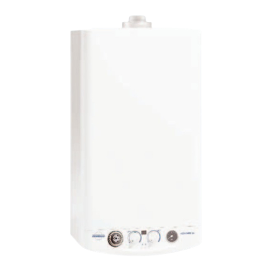
Do not interfere with any sealed components, and use the appliance only in accordance with these instructions. INTRODUCTION The MORCO FEB-24ED 3 is wall hung, room sealed, fan assisted, microprocessor controlled, fully modu- lating gas combination boiler for providing both central heating and domestic hot water. -
Page 5: Turning The Boiler Off
USING THE PROGRAMMABLE CLOCK 1. Set the correct time by rotating the minute hand until the arrowhead points at the correct time on the 24 hour dial. 2. Check the position of the manual override switch (just to the bottom of the clock face). -
Page 6: Frost Protection
- Caution: The boiler can produce water at over 70°C when in central heating mode. If you run a hot tap when the boiler has been heating the radiators, the initial through the hot tap could be very hot. DO NOT PLACE YOUR HANDS under the tap or use the shower until this initial has passed. - Page 7 PRECAUTIONS AGAINST FREEZING DURING WINTER STORAGE If the holiday home is to be un-occupied during cold periods, and whenever there is a threat of freezing, the domestic hot and cold water circuit must be drained as follows: -Turn off the cold water supply. -Open all hot and cold taps.
-
Page 8: General Specifications
2.- GENERAL SPECIFICATIONS The Fagor MORCO FEB-24ED 3 is a wall hung, Central heating expansion vessel. room sealed, fan assisted, microprocessor con- air pressure switch . Prevents the boil- trolled fully modulating gas combination boiler for if there is insu cient air supply due to a fault providing both central heating and domestic hot or blockage. - Page 9 FEB-24ED 3 ELECTRICAL CIRCUIT DIAGRAM 1.- Mains connection 11.- Room Stat (optional) 2.- Earth 12.- Clock Connection 3.- Fan 13.- Modulating Solenoid Valve 4.- Pump 14.- Flame Sensor 5.- Ignition 15.- High limit stat 6.- Burner Solenoid valve 1 7.- Burner solenoid valve 2 17.- Central Heating return thermisthor 8.- Front panel control 18.- Pressure Switch...
-
Page 10: Technical Data
3.- TECHNICAL DATA Model FEB-24ED 3 Ë Category II2H3P Type 24.5 Maximum output Btu/h 83,653.41 Central heating and domestic hot water performances. Minimum output Btu/h 26,291.07 Maximum 28.9 Nominal central heating and domestic hot input (Gr oss) Minimum Maximum 25.5 Nominal central heating and domestic hot water input (Nett) Minimum... - Page 11 DIMENSIONS AND CONNECTIONS DETAILS T.A. 1.- 3/4” BSP Central heating return 2.- Mains cable 3.-1/2” BSP Domestic cold water inlet 4.- 3/4” BSP Gas inlet 5.- 1/2” BSP D.H.W. outlet 6.- 3/4” BSP Central heating ow 8.- Pressure Relief Valve 9.- Draining valve for central heating T.A.:Room thermostat connection asdasdfasdfasdfasdf...
-
Page 12: General Installation Requirements
4.- GENERAL INSTALLATION REQUIREMENTS 4.1 RECOMMENDATIONS - Ventilation requirements as stated in this manual must be observed. FOR THE USER - Minimum clearance as stated in the technical data This appliance must be installed, adjusted or adapt- must be observed. ed for use with another type of gas, only by a quali- 4.3 FLUE TERMINAL POSITION fied and competent person. - Page 13 15mm before the boil- - A full bore isolation cock must be fitted in the sup- ply close to the boiler or use morco part number FW0391. - The complete installation must be tested for gas soundness.
-
Page 14: Pressure Relief Valve
Expansion vessel. over 150 ppm, the fitting of an in line scale inhibitor may be an advantage. The following table gives the maximum system vol- ume that the integral 7 l expansion vessel can sustain D H W Performance graph under different temperature conditions. -
Page 15: Installation Instructions
5.- INSTALLATION INSTRUCTIONS 5.1 BOILER PACKAGING mostat is 24V (normally closed). Any 24V controls may be used, but gold contacts are recommended. The boilers are supplied in di erent packagings: DO NOT under any circumstances use a mains sup- - Boiler ply to the stat as you will blow the P.C.B. - Page 16 External Probe Curves 5.4 WATER AND GAS CONNECTION Connect the boiler up in such a way as to leave the connecting pipes self supporting and free from any stress. Check that the gas pipe complies with the require- ments of section 4.6 In order for the boiler to function correctly and to have a long working life, the central heating system must be properly designed, making sure that the temper-...
-
Page 17: Commissioning Instructions
6.- COMMISSIONING INSTRUCTIONS Before commissioning the appliance, the whole gas 6.3 GAS CIRCUIT installation including the meter (if fitted) MUST be Purge the gas circuit as described above. Turn on purged and tested for gas soundness. the gas cock to the installation and check that there IMPORTANT: open all doors and windows, extin- are no leaks using leak detection fluid. -
Page 18: Routine Servicing Instructions
6.5.5 Appliance safety lock-out 6.7 USER’S INSTRUCTIONS If the boiler develops a fault the red LED will illumi- Upon completion of testing the system, the installer nate and the digital display shows the relevant fault should: code; see p19. - Give the 'users Instructions' to the owner and To restart the boiler Set the main control on the emphasise their responsibilities under the "Gas position and then turn it back to the chosen position. -
Page 19: Troubleshooting
FAN CLEANING sure should increase slightly as the temperature rises. Finally check the filters which is situated in the Remove the fan (3 screws) and using a soft brush cold water inlet pipe remove any build up of debris from the fan blades. BURNER PRESSURE BURNER HEAT... -
Page 20: Fault Code Table
For more detailed servicing information, workshop manuals, technical advice, spare parts, product training, please phone us on 01482 325456 or contact us at the address below. MORCO PRODUCTS LTD Morco House, Riverview Road, Beverley, East Yorkshire HU17 0LD TEL:01482 325456 FAX:01482 212869 EMAIL: sales@morcoproducts.co.uk WEBSITE: www.morcoproducts.co.uk...
Need help?
Do you have a question about the FEB24ED3* and is the answer not in the manual?
Questions and answers