Advertisement
System Power Amplifier (SPA)
Installation Guide
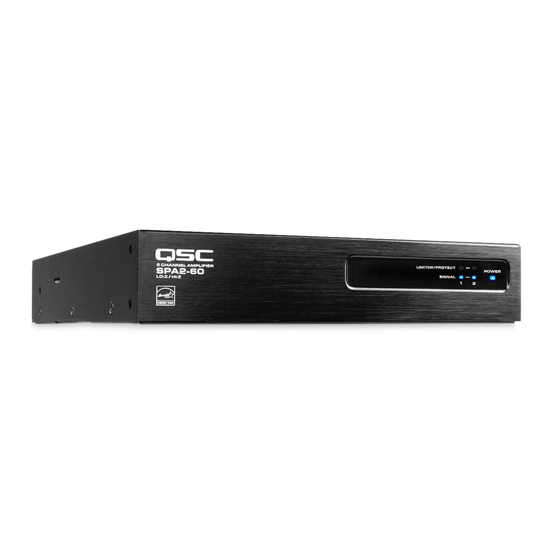
SPA2-60 Amplifi er
SPA4-60 Amplifi er
The term "WARNING!" indicates instructions regarding personal safety. If the instructions are not followed the result may be bodily injury or death.
The term "CAUTION!" indicates instructions regarding possible damage to physical equipment. If these instructions are not followed, it may result in
damage to the equipment that may not be covered under the warranty.
The term "IMPORTANT!" indicates instructions or information that are vital to the successful completion of the procedure.
The term "NOTE" is used to indicate additional useful information.
The intent of the lightning fl ash with arrowhead symbol in a triangle is to alert the user to the presence of un-insulated "dangerous"
voltage within the product's enclosure that may be of suffi cient magnitude to constitute a risk of electric shock to humans.
The intent of the exclamation point within an equilateral triangle is to alert the user to the presence of important safety, and operating
and maintenance instructions in this manual.
What's in the Box
SPA4-60 (1x)
TD-000500-01 -A
*TD-000500-01 *
EXPLANATION OF SYMBOLS
(1x)
(2x)
(1x)
SPA2-60 (1x)
SPA4-60 (2x)
SPA4-60 (1x)
(1x)
(6x)
SPA2-60 (1x)
Warranty TD-000453
(2x)
(6x)
SPA2-60 (1x)
(1x)
Safety Information TD-000337
(2x)
(4x)
(1x)
Advertisement

Related Manuals for QSC SPA2-60


Summary of Contents for QSC SPA2-60
-
Page 1: Installation Guide
System Power Amplifier (SPA) Installation Guide SPA2-60 Amplifi er SPA4-60 Amplifi er EXPLANATION OF SYMBOLS The term “WARNING!” indicates instructions regarding personal safety. If the instructions are not followed the result may be bodily injury or death. The term “CAUTION!” indicates instructions regarding possible damage to physical equipment. If these instructions are not followed, it may result in damage to the equipment that may not be covered under the warranty. -
Page 2: Table Of Contents
• Recommend 1RU (1.75 in / 44.45 mm) space above the amplifi er. • Minimum open space of 6 inches measured from back of amplifi er. NOTE: QSC System Power Amplifi ers contain advanced protection circuitry which allows them to reduce output power in order to maintain safe operating temperatures. -
Page 3: One Amplifi Er 19-Inch Rack (Left Or Right Mount)
A. One Amplifi er 19-inch Rack (Left or Right Mount) Figure 2 Top Side Top Side Front Panel Front Panel — Figure 2 — B. Two Amplifi ers 19-inch Rack (Front or Rear Facing Out) Figure 3 Bottom Side Amp 2 Front Panel Bottom Side Amp 1... -
Page 4: One Amplifi Er Half Rack (Front Or Rear Facing Out)
Front or Rear Facing Out C. One Amplifi er Half Rack ( Figure 4 1. (1) Top Side Front Panel 2. (2) 3. (6) Top Side Rear Panel — Figure 4 — D. Under Table or on Wall Figure Mounting Surface Not supplied –... -
Page 5: Free-Standing On Desk/Table
E. Free-Standing on Desk/Table Figure 6 Bottom Side Front Panel — Figure 6 — F. Plenum Installation Confi gure amplifi er per option D Under Table or on Wall. Figure 7 Top Side Front Panel Plenum Kit - Suitable for Air Handling Spaces only when used with optional Plenum Kit (FG-000995-00) sold separately. - Page 6 Front Panel Limiter / Protect Input Signal Power Limiter / Protect Input Signal Power Red – Protect / Mute Blue – Present Blue – On Red – Protect / Mute Blue – Present Blue – On Orange – Limiter on Orange –...
- Page 7 Figure 12 – Figure 13 SPA2-60 SPA4-60 — Figure 13 — — Figure 12 — Input Connectors SPA2-60 Connector Figure 14 – Figure 15 SPA4-60 Connector Figure 16 – Figure 17 — Figure 14 — — Figure 16 — — Figure 15 —...
- Page 8 Balanced and Unbalanced Inputs Figure 18 Balanced Unbalanced Unbalanced Inputs: jumper between (-) negative and ground. — Figure 18 — Stereo Mode Inputs Figure 19 – Figure 21 & & & — Figure 20 — Outputs — Figure 19 — CAUTION!: Do not connect any output to ground.
- Page 9 4 or 8-ohm Bridged Mode Inputs Figure 22 – Figure 24 & & & — Figure 23 — Outputs — Figure 22 — CAUTION!: Do not connect any output to ground. — Figure 24 — 70V / 100V Bridge Mode Figure 25 –...
- Page 10 V = +10Vdc reference output C = 0-10Vdc control input Figure 29 – Figure 31 C @ 10V = Max Volume C @ 0V = Mute SPA2-60 10 kΩ 3.5mm, 5-pin Standby Switch in Run Mode Standby Switch in Standby Mode SPA4-60 —...
- Page 11 Specifi cations Channels SPA2-60 2 Channels SPA4-60 4 Channels Stereo Mode (all channels driven) 8 60 W 4 60 W Bridged Outputs (per bridged output pair) 8 & 4 200 W 250 W 100V 250 W Frequency Response (4 and 8) 20 Hz - 20 kHz +/- 0.1 dB...
- Page 12 © 2015 QSC Audio Products, LLC. All rights reserved. QSC and the QSC logo are registered trademarks of QSC Audio Products, LLC in the U.S. Patent and Trademark offi ce and other countries. All other trademarks are the property of their respective owners.
Need help?
Do you have a question about the SPA2-60 and is the answer not in the manual?
Questions and answers