Table of Contents
Advertisement
Quick Links
Advertisement
Chapters
Table of Contents

Related Manuals for koppel KV 24CC-ARF21


Summary of Contents for koppel KV 24CC-ARF21
- Page 2 Contents CONTENTS Part 1 General Information ....................1 Part 2 Indoor Units ......................... 6 Part 3 Outdoor Units ......................63 Part 4 Installation ........................75 Part 5 Electrical Control System ..................103 ...
- Page 3 General Information Part 1 General Information 1. Model Lists ....................2 2. External Appearance ..................3 2.1 Indoor Units ..................3 2.2 Outdoor Units ..................3 3. Nomenclature ..................... 4 4. Features ...................... 5...
-
Page 4: Model Lists
Model Lists 1. Model Lists 1.1 Indoor Units R410A (capacity multiplied by 1000Btu/h) Type Function Four-way cassette Cooling √ Super-slim Four-way cassette Cooling √ √ Ceiling & floor Cooling √ generation ceiling & floor Cooling √ √ √ Floor-standing Cooling √... -
Page 6: Nomenclature
RF2 - R410A Power supply A - 220/1/60 C - 220/3/60 B - 380/3/60 Model Type CC - Cassette Type FM - Floor mount CM - Ceiling-floor ODU - Universal Outdoor Unit Capacity (×1000Btu/h) Compressor type V - Inverter Koppel... -
Page 7: Features
Features Features 4.1 Universal outdoor unit design Indoor unit with the same capacity as the outdoor unit can be matched. 4.2 High efficiency and energy saving. Thanks to the DC inverter technology and optimized piping system, the EER and COP of whole series can easily reach A-class. -
Page 8: Part 2 Indoor Units
Indoor Units Part 2 Indoor Units Four-way Cassette Type ............7 Super Slim Cassette Type ..........20 Ceiling & Floor Type ............33 Generation Ceiling & Floor Type ........45 Floor-standing Type ............53 ... -
Page 9: Table Of Contents
Four-way Cassette Type Four-way Cassette T ype 1. Features ......................8 2. Dimensions ....................11 3. Service Space ....................12 4. Wiring Diagrams ................... 13 5. Capacity Tables .................... 14 6. Air Velocity Distributions(Reference Data) ..........15 7. Electric Characteristics ................16 8. -
Page 10: Features
Features 1. Features (1) Low operation noise —Streamline plate ensures quietness —Creates natural and comfortable environment (2) Efficient cooling——Equal, fast and wide range cooling (3) Excellent performance. The optimal evaporator & sufficient airflow volume guarantees the excellent capacity (4) The adoption of the most advanced 3- Dimensional Screw fan —Reduces the air resistance passing through —Smoothes the air flow —Makes air speed distribution to the heat exchange uniform... - Page 11 Features (8) Different color panels to be chosen: White、Gray、Blue、Black (9) Swing angle of louver Add one more swing motor, one motor drive two louvers. Controlling the interspace of each part, minimizing the angle loss. The swing angle of the first louver are 40~42 degrees and the second louver are 37~38 degrees. New evaporator and inner configuration design can acquire high heat-exchanger effect.
- Page 12 Features (15) Reserve spaces for air side-outlet, it is available to connect duct pipe hence air supplying from the four sides to nearby small room.. (16) The connecting pipe and drop height is higher. Max. pipe length up to 50m (refer to ①) , and Max. drop height up to 30m(refer to ②).
-
Page 13: Dimensions
Dimensions 2. Dimensions Unit: mm MODEL KV24CC-ARF21 Ф9.52 Ф15.9 >260... -
Page 14: Service Space
Service Space 3. Service Space >1000mm >1000mm... -
Page 15: Wiring Diagrams
Wiring Diagrams 4. Wiring Diagrams KV24CC-ARF21... -
Page 16: Capacity Tables
Capacity Tables 5. Capacity Tables 5.1 Cooling Capacity KV24CC-ARF21 Cooling Outdoor conditions (DB) Indoor Conditions (kW) 21ºC 28ºC 35ºC 43ºC 7.52 7.15 6.79 6.50 21/15ºC DB/WB 5.56 5.51 5.43 5.46 Input 2.10 2.28 2.38 2.46 7.74 7.37 7.01 6.57 24/17ºC DB/WB 5.80 5.75 5.68... -
Page 17: Air Velocity Distributions(Reference Data)
Air Velocity and Temperature Distributions (Reference Data) Reference Data 6. Air Velocity Distributions ( Airflow velocity... -
Page 18: Electric Characteristics
Electric Characteristics 7. Electric Characteristics Indoor Unit Power Supply Model Voltage KV24CC-ARF21 220-230 Note: MFA: Max. Fuse Amps. (A) 8. Sound Levels 1.4m Microphone Noise level dB(A) Model KV24CC-ARF21 40.5... -
Page 19: Accessories
Accessories 9. Accessories Name Shape Quantity Installation Fittings Installation paper board Soundproof / insulation sheath(on Tubing & Fittings some models) Out-let pipe sheath(on some models) Out-let pipe clasp(on some models) Drainpipe Fittings Drain joint(on some models) Seal ring Remote controller & Its Frame Remote controller holder Remote controller &... -
Page 20: The Specification Of Power
The Specification of Power 10. The Specification of Power KV24CC-ARF21 Model Phase 1-phase Frequency and 220-230V, 60Hz Voltage INDOOR UNIT POWER POWER WIRING 3×1.0 CIRCUIT BREAKER/ 15/10 FUSE(A) Phase 1-phase Frequency and 220-230V, 60H Voltage OUTDOOR UNIT POWER POWER WIRING 3X2.5 CIRCUIT BREAKER/ 30/20... -
Page 21: Field Wiring
Field Wiring 11. Field Wiring KV24CC-ARF21... -
Page 22: Super Slim Cassette Type
Super Slim Cassette Type Super Slim Cassette Type 1. Features ..............21 2. Dimensions ............. 25 3. Service Space ............26 4. Wiring Diagrams ............ 27 5. Electric Characteristics ......... 28 6. Sound Levels ............29 ... -
Page 23: Features
Features 1. Features 1.1 Overview Compact design, super slim body size, less space required in installation Each louver can be separately controlled, more comfortable air blow is possible. Auto-lifting panel design, more convenient to clean and maintain the filter. (optional) Old Cassette New Slim Cassette Reduction... - Page 24 Features New air-intake 1.3 Optional ionizer generator Ionizer generator is optional to get cleaner refreshing air to your room. Ionizer can be switched on or off by remote controller. When pressing the Clean Air button on the remote controller, Ionizer will work and the indicator light on display board will light.
- Page 25 Features 1.4 External air duct design Reserve external air duct, for more flexible air supply design. 1.5 Built-in drain pump Due to the improvement of structure, is it more convenient to repair or replace the drain pump. Drain Pump With built-in drain pump to make sure that condensed water will drain out reliably.
- Page 26 Features Reserve terminals for the connection of alarm lamp and long-distance on-off controller, more human control interface. Alarm lamp Long-distance on-off controller 1.7 Standard touch screen wired controller Touch screen wired controller is standard, with error code indication function. Better man-machine conversation interface.
-
Page 27: Dimensions
Dimensions 2. Dimensions Capacity (Btu/h) >275 >275... -
Page 28: Service Space
Service Space 3. Service Space >1000mm >1000mm... -
Page 29: Wiring Diagrams
Wiring Diagrams 4. Wiring Diagrams KV36CC-ARF21B KV48CC-ARF21B... -
Page 30: Electric Characteristics
Electric Characteristics Electric Characteristics Power Indoor Unit Supply Model Voltage KV36CC-ARF21B 220-230 KV48CC-ARF21B 220-230 Note : MFA: Max. Fuse Amps. (A) -
Page 31: Sound Levels
Sound Levels Sound Levels 1.4m Microphone Noise level dB(A) Model KV36CC-ARF21B KV48CC-ARF21B... -
Page 32: Accessories
Accessories Accessories Name Shape Quantity Installation Fittings Installation paper board Soundproof / insulation sheath(on Tubing & Fittings some models) Out-let pipe sheath(on some models) Out-let pipe clasp(on some models) Drainpipe Fittings Drain joint(on some models) Seal ring Remote controller & Its Frame Remote controller holder Remote controller &... -
Page 33: The Specification Of Power
The Specification of Power 8. The Specification of Power KV36CC-ARF21B KV48CC-ARF21B Model Phase 1-phase 1-phase Frequency 220-230V, 60Hz 220-230V, 60Hz Voltage INDOOR UNIT POWER POWER WIRING 3×1.0 3×1.0 CIRCUIT BREAKER/ 15/10 15/10 FUSE(A) Phase 1-phase 1-phase Frequency 220-230V, 60H 220-230V, 60H Voltage OUTDOOR UNIT POWER POWER... -
Page 34: Field Wiring
Field Wiring 9. Field Wiring KV36CC-ARF21B KV48CC-ARF21B... -
Page 35: Ceiling & Floor Type
Ceiling & Floor Type Ceiling & Floor Type 1. Features ....................34 2. Dimensions ................... 35 3. Service Space..................36 4. Wiring Diagrams ................... 37 5. Capacity Tables ..................38 6. Air Velocity Distributions(Reference Data) ........39 7. Electric Characteristics ................ 41 8. -
Page 37: Dimensions
Dimensions 2. Dimensions a. Wall mounting installation b. Ceiling installation Capacity (Btu/h) KV24CM-ARF21... -
Page 38: Service Space
Service Space 3. Service Space... -
Page 39: Wiring Diagrams
Wiring Diagrams 4. Wiring Diagrams KV24CM-ARF21... -
Page 40: Capacity Tables
Capacity Tables 5. Capacity Tables 6.1 Cooling Capacity KV24CM-ARF21 Cooling Outdoor conditions (DB) Indoor Conditions (kW) 21ºC 28ºC 35ºC 43ºC 7.52 7.15 6.79 6.50 21/15ºC DB/WB 5.56 5.51 5.43 5.46 Input 2.10 2.28 2.38 2.46 7.74 7.37 7.01 6.57 24/17ºC DB/WB 5.80 5.75 5.68... -
Page 41: Air Velocity Distributions(Reference Data)
Air Velocity and Temperature Distributions(Reference Data) Air Velocity Distributions(Reference Data) Discharge angle 60° (CEILING) Airflow velocity... - Page 42 Air Velocity and Temperature Distributions(Reference Data) Discharge angle 60°(FLOOR) Airflow velocity...
-
Page 43: Electric Characteristics
Electric Characteristics 7. Electric Characteristics Indoor Unit Power Supply Model Voltage KV24CM-ARF21 220-230 Note: MFA: Max. Fuse Amps. (A) 8. Sound Levels Microphone 1.5m Air outlet side Microphone Ceiling Floor Noise level dB(A) Model KV24CM-ARF21... -
Page 44: Accessories
Accessories 9. Accessories Name Shape Quantity 1.Hook Installation fittings 2.Hanging arm 3. Remote controller Remote controller & Its 4. Remote controller holder holder 5. Mounting screw (ST2.9×10-C-H) 6. Alkaline dry batteries (AM4) 7. Owner's manual Others 8. Installation manual 9. Remote controller manual... -
Page 45: The Specification Of Power
The Specification of Power 10. The Specification of Power KV24CM-ARF21 Model Phase 1-phase Frequency and 220-230V, 60Hz Voltage INDOOR UNIT POWER POWER WIRING 3×1.0 CIRCUIT BREAKER/ 15/10 FUSE(A) Phase 1-phase Frequency and 220-230V, 60H Voltage OUTDOOR UNIT POWER POWER WIRING 3X2.5 CIRCUIT BREAKER/ 30/20... -
Page 46: Field Wiring
Field Wiring 11. Field Wiring KV24CM-ARF21... - Page 47 3rd Generation Ceiling & Floor Type Gener ation Ceiling & Floor T ype 1. Features ..............46 2. Dimensions ............. 47 3. Service Space ............48 4. Wiring Diagrams ............ 49 5. Electric Characteristics ......... 50 ...
-
Page 49: Dimensions
Dimensions Dimensions Wiring connection port Drain discharge port Fresh air intake Refrigerant pipe hole Hanging arm Capacity (Btu/h) 1285 1200 1650 1565... -
Page 50: Service Space
Service Space Service Space... -
Page 51: Wiring Diagrams
Wiring Diagrams Wiring Diagrams KV36CM-ARF21B KV48CM-ARF21B... -
Page 52: Electric Characteristics
Electric Characteristics Electric Characteristics Indoor Units Power Supply Model Voltage Min. Max. KV36CM-ARF21B 220-230V 198V 242V KV48CM-ARF21B 220-230V 198V 242V Note: MFA: Max. Fuse Amps. (A) Sound Levels Microphone 1.5m Air outlet side Microphone Ceiling Floor Noise level dB(A) Model KV36CM-ARF21B KV48CM-ARF21B... -
Page 53: Accessories
Accessories Accessories 1. Remote controller Remote controller & Its 2. Remote controller holder holder 3. Mounting screw (ST2.9×10-C-H) 4. Alkaline dry batteries (AM4) 5. Owner's manual Others 6. Installation manual 7. Remote controller manual The Specification of Power KV36CM-ARF21B KV48CM-ARF21B Model Phase 1-phase... -
Page 54: Field Wiring
Field Wiring Field Wiring KV36CM-ARF21B KV48CM-ARF21B... -
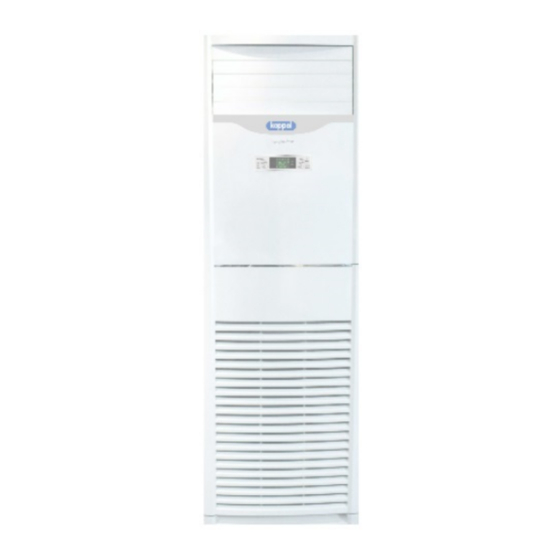
Page 55: Floor-Standing Type
GA Floor-standing Type Floor-standing T ype Features ..............54 Dimensions ............55 Service Space ............56 Wiring Diagrams ........... 57 Electric Characteristics ........58 Sound Levels ............59 Accessories ............ -
Page 57: Dimensions
Dimensions 2. Dimensions Dimension W(mm) D(mm) H(mm) Mode 1800 KV36FM-ARF21 KV60FM-ARF21 1925... -
Page 58: Service Space
Service Space 3. Service Space GA Floor-standing Type... -
Page 59: Wiring Diagrams
Wiring Diagrams 4. W iring Diagrams KV36FM-ARF21 KV60FM-ARF21... -
Page 60: Electric Characteristics
Electric Characteristics 5. Electric Characteristics Indoor Units Power Supply Model Voltage Min. Max. KV36FM-ARF21 220-230V 198V 242V KV60FM-ARF21 220-230V 198V 242V Note: MFA: Max. Fuse Amps. (A) -
Page 61: Sound Levels
Sound Levels 6. Sound Levels Noise level dB(A) Model KV36FM-ARF21 KV60FM-ARF21... -
Page 62: Accessories
Accessories 7. Accessories... -
Page 63: The Specification Of Power
The Specification of Power 8. The Specification of Power KV36FM-ARF21 KV60FM-ARF21 Model Phase 1-phase 1-phase Frequency and Voltage 220-230V, 60Hz 220-230V, 60Hz INDOOR UNIT POWER POWER WIRING (mm 3×1.0 3×1.0 CIRCUIT BREAKER/ FUSE(A) 15/10 15/10 Phase 1-phase 3-phase Frequency and Voltage 220-230V, 60H 220-230V, 60H OUTDOOR UNIT POWER... -
Page 64: Field Wiring
Field Wiring 9. Field Wiring KV36FM-ARF21 KV60FM-ARF21... -
Page 65: Part 3 Outdoor Units
Outdoor Units Part 3 Outdoor Units 1. Dimensions ...................64 2. Service Space..................66 3. Piping Diagrams ...................67 4. Wiring Diagrams ...................68 5. Electric Characteristics ...............72 6. Operation Limits ...................73 7. Sound Levels ..................74 ... -
Page 66: Dimensions
Dimensions Dimensions Unit: mm MODEL KV24ODU-ARF21 KV36ODU-ARF21 / B... - Page 67 Dimensions Unit: mm MODEL KV48ODU-ARF21B 1369 KV60ODU-CRF21 1369...
-
Page 68: Service Space
Service Space Service Space (Wall or obstacle) More than 30cm Air inlet More than 60cm More than 30cm Maintain channel Air inlet More than 60cm Air outlet More than 200cm... -
Page 69: Piping Diagrams
Piping Diagrams Piping Diagrams KV24ODU-ARF21 INDOOR OUTDOOR Electronic CAPILIARY TUBE expansion valve LIQUID SIDE T3 Condenser temp. sensor HEAT EXCHANGE HEAT (EVAPORATOR) EXCHANGE T1 Room temp. T4 Ambient T2 Evaporator (CONDENSER) sensor temp. sensor temp. sensor middle T2B Evaporator temp. sensor outlet T5 Discharge Accumulator... -
Page 70: Wiring Diagrams
Wiring Diagrams Wiring Diagrams KV24ODU-ARF21(220075301510) KV24ODU-ARF21(220075301740) - Page 71 Wiring Diagrams KV36ODU-ARF21 /B (220075501730) KV36ODU-ARF21 /B (220075502120)
- Page 72 Wiring Diagrams KV48ODU-ARF21B...
- Page 73 Wiring Diagrams KV60ODU-CRF21...
-
Page 74: Electric Characteristics
Electric Characteristics Electric Characteristics Outdoor Unit Power Supply Model Voltage Min. Max. KV24ODU-ARF21 220-230 KV36ODU-ARF21 /B 220-230 KV48ODU-ARF21B 220-230 KV60ODU-CRF21 220-230 Note: MFA: Max. Fuse Amps. (A) -
Page 75: Operation Limits
Operation Limits Operation Limits Temperature Cooling operation Drying operation Mode Room temperature 17℃~32℃ 17℃~32℃ 0℃~50℃ (-15℃~50℃:For Outdoor temperature 0℃~50℃ models with low temperature cooling system) CAUTION: 1. If the air conditioner is used beyond the above conditions, certain safety protection features may come into operation and cause the unit to operate abnormally. -
Page 76: Sound Levels
Sound Levels Sound Levels Outdoor Unit Microphone 1.0m Note: H= 0.5 × height of outdoor unit Model Noise level dB(A) KV24ODU-ARF21 KV36ODU-ARF21 /B KV48ODU-ARF21B KV60ODU-CRF21... -
Page 77: Part 4 Installation
Installation Part 4 Installation Installation Procedure ..........76 Location selection .............77 Indoor unit installation ..........78 Outdoor unit installation (Side Discharge Unit) ..97 Refrigerant pipe installation ........92 Drainage pipe installation .........94 ... -
Page 78: Installation Procedure
Installation Procedure 1. Installation Procedure Indoor unit installation Outdoor unit installation location selection location selection Indoor unit installation Outdoor unit installation Refrigerant pipe Refrigerant pipe installation and insulation installation and insulation Drainage pipe installation Drainage pipe installation and insulation and insulation Vacuum drying and leakage checking Additional refrigerant charge Insulation the joint part of refrigerant pipe... -
Page 79: Location Selection
Location selection 2. Location selection 2.1 Indoor unit location selection The place shall easily support the indoor unit’s weight. The place can ensure the indoor unit installation and inspection. The place can ensure the indoor unit horizontally installed. ... -
Page 80: Indoor Unit Installation
Indoor unit installation 3. Indoor unit installation 3.1 Cassette indoor unit installation 3.1.1 Service space for indoor unit Model Remark 30-60 Cooling (ARF21) >330 R410A and R22 36-48 Cooling (ARF21B) >275 R410A and R22 3.1.2 Bolt pitch 3.1.3 Install the pendant bolt Select the position of installation hooks according to the hook holes positions showed in upper picture. - Page 81 Indoor unit installation Drill four holes of Ø12mm, 45~50mm deep at the selected positions on the ceiling. Then embed the expansible hooks (fittings). 3.1.4 Install the main body Make the 4 suspender through the 4 hanger of the main body to suspend it. Adjust the hexangular nuts on the four installation hooks evenly, to ensure the balance of the body.
- Page 82 Indoor unit installation 3.1.5 Install the panel Remove the grille Remove the 4 corner covers. Hang the panel to the hooks on the mainbody.
- Page 83 Indoor unit installation Tighten the screws under the panel hooks till the panel closely stick on the ceiling to avoid condensate water. Hang the air-in grill to the panel, then connect the lead terminator of the swing motor and that of the control box with corresponding terminators on the body respectively.
- Page 84 Indoor unit installation Ceiling & floor indoor unit installation 3.3.1 Service space for indoor unit 3.3.2 Bolt pitch ① Ceiling installation Capacity (Btu/h) KV24CM-ARF21 ② Floor standing installation...
- Page 85 Indoor unit installation 3.3.3 Install the pendant bolt ① Ceiling installation Select the position of installation hooks according to the hook holes positions showed in upper picture. Drill four holes of Ø12mm, 45~50mm deep at the selected positions on the ceiling. Then embed the expansible hooks (fittings).
- Page 86 Indoor unit installation Hang the unit on the hanging arm by sliding backward. Securely tighten the mounting bolts on both sides. For some of the models 60 please securely tighten the mounting bolts on both sides. Then install the side panels and grilles back to the main unit. ②...
- Page 87 Indoor unit installation 3.4 3rd generation ceiling & floor indoor unit installation 3.4.1 Service space for indoor unit 3.4.2 Bolt pitch ① Ceiling installation Capacity (Btu/h) 1200 1565 ② Wall-mounted installation...
- Page 88 Indoor unit installation 3.4.3 Install the pendant bolt ① Ceiling installation Select the position of installation hooks according to the hook holes positions showed in upper picture. Drill four holes of Ø12mm, 45~50mm deep at the selected positions on the ceiling. Then embed the expansible hooks (fittings).
- Page 89 Indoor unit installation Locate the hanging arm on the hanging screw bolt. Prepare the mounting bolts on the unit. Put the side panels and grilles back. ② Wall-mounted installation Hang the indoor unit by insert the tapping screws into the hanging arms on the main unit. (The bottom of body can touch with floor or suspended, but the body must install vertically.)
- Page 90 Indoor unit installation 3.5 Floor standing indoor unit installation 3.5.1 Service space for indoor unit a. A place which provides the spaces around the indoor unit as required above in the diagram. b. A place where is no obstacle near the inlet and outlet area. c.
- Page 91 Indoor unit installation 3.5.2.3. Take the Pipe Clip off before connecting the pipes and wiring; fit it when these finished. Use accessories to connect the pipes/wires on both sides and back side.
- Page 92 Outdoor unit installation (Side Discharge Unit) 4. Outdoor unit installation (Side Discharge Unit) 4.1 Service space for outdoor unit 4.2 Bolt pitch Model 4.3 Install the Unit Since the gravity center of the unit is not at its physical center, so please be careful when lifting it with a sling. Never hold the inlet of the outdoor unit to prevent it from deforming.
- Page 93 Outdoor unit installation (Side Discharge Unit) Do not touch the fan with hands or other objects. Do not lean it more than 45, and do not lay it sidelong. Make concrete foundation according to the specifications of the outdoor units. Fasten the feet of this unit with bolts firmly to prevent it from collapsing in case of earthquake or strong wind.
-
Page 94: Refrigerant Pipe Installation
Refrigerant pipe installation 5. Refrigerant pipe installation 5.1 Maximum pipe length and height drop Considering the allowable pipe length and height drop to decide the installation position. Make sure the distance and height drop between indoor and outdoor unit not exceeded the data in the following table. Model Max. - Page 95 Refrigerant pipe installation 5.2.10 Set the wall conduit 5.2.11 Set the supporter for the pipe. 5.2.12 Locate the pipe and fix it by supporter For horizontal refrigerant pipe, the distance between supporters should not be exceed 1m. For vertical refrigerant pipe, the distance between supporters should not be exceed 1.5m. 5.2.13 Connect the pipe to indoor unit and outdoor unit by using two spanners.
-
Page 96: Drainage Pipe Installation
Drainage pipe installation 6. Drainage pipe installation Install the drainage pipe as shown below and take measures against condensation. Improper installation could lead to leakage and eventually wet furniture and electrical devices. 6.1 Installation principle Ensure at least 1/100 slope of the drainage pipe ... - Page 97 Drainage pipe installation 6.2.3 Individual design of drainage pipe system The drainage pipe of air conditioner shall be installed separately with other sewage pipe, rainwater pipe and drainage pipe in building. The drainage pipe of the indoor unit with water pump should be apart from the one without water pump. 6.2.4 Supporter gap of drainage pipe ...
- Page 98 Drainage pipe installation Indoor unit More than 50mm Plug More than 25mm Water storage pipe 6.2.7 Lifting pipe setting of indoor unit with water pump The length of lifting pipe should not exceed the pump head of indoor unit water pump. Pump head of big four way cassette: 750mm Pump head of compact four way cassette: 500mm ...
-
Page 99: Outdoor Unit Installation (Side Discharge Unit)
Drainage pipe installation 6.3 Drainage test 6.3.1 Water leakage test After finishing the construction of drainage pipe system, fill the pipe with water and keep it for 24 hours to check whether there is leakage at joint section. 6.3.2 Water discharge test Natural drainage mode(the indoor unit with outdoor drainage pump) Infuse above 600ml water through water test hole slowly into the water collector, observe whether the water can discharge through the transparent hard pipe at drainage outlet. -
Page 100: Vacuum Drying And Leakage Checking
Vacuum Drying and Leakage Checking 7. Vacuum Drying and Leakage Checking 7.1 Purpose of vacuum drying Eliminating moisture in the system to prevent the phenomena of ice-blockage and copper oxidation. Ice-blockage shall cause abnormal operation of system, while copper oxide shall damage compressor. ... -
Page 101: Additional Refrigerant Charge
Additional refrigerant charge 8. Additional refrigerant charge After the vacuum drying process is carried out, the additional refrigerant charge process need to be performed. The outdoor unit is factory charged with refrigerant. The additional refrigerant charge volume is decided by the diameter and length of the liquid pipe between indoor and outdoor unit. -
Page 102: Engineering Of Insulation
Engineering of insulation 9. Engineering of insulation 9.1 Insulation of refrigerant pipe 9.1.1 Operational procedure of refrigerant pipe insulation Cut the suitable pipe → insulation (except joint section) → flare the pipe → piping layout and connection→ vacuum drying → insulate the joint parts 9.1.2 Purpose of refrigerant pipe insulation During operation, temperature of gas pipe and liquid pipe shall be over-heating or over-cooling ... -
Page 103: Engineering Of Electrical Wiring
Engineering of electrical wiring 9.2.3 Insulation material selection for drainage pipe The insulation material should be flame retardant material, the flame retardancy of the material should be selected according to the local law. Thickness of insulation layer is usually above 10mm. ... -
Page 104: Test Operation
Test operation 11. T est operation 11.1 The test operation must be carried out after the entire installation has been completed. 11.2 Please confirm the following points before the test operation. The indoor unit and outdoor unit are installed properly. ... -
Page 105: Part 5 Electrical Control System
Electrical Control Function Part 5 Electrical Control System Electrical Control Function ........ 104 Troubleshooting ..........110 Controller ............. 134 ... - Page 106 Electrical Control Function 1. Electrical Control Function 1.1 Definition T1: Indoor room temperature T2: Coil temperature of indoor heat exchanger middle. T2B: Coil temperature of indoor heat exchanger outlet. T3: Coil temperature of condenser T4: Outdoor ambient temperature T5: Compressor discharge temperature 1.2 Main Protection 1.2.1 Time delay at restart for compressor.
-
Page 107: Operation Modes And Functions
Electrical Control Function 1.3 Operation Modes and Functions 1.3.1 Fan mode ( 1) Outdoor fan and compressor stop. (2) Temperature setting function is disabled, and no setting temperature is displayed. (3) Indoor fan can be set to high/(med)/low/auto. (4) The louver operates same as in cooling mode. (5) Auto fan: High Medium... - Page 108 Electrical Control Function When T4 <15 ℃ and T3 < 30 ℃, the unit will enter into low ambient cooling mode. The outdoor fan will choose speed according to T3. When T3≥38 ℃ or when T4≥20 ℃, the outdoor fan will choose the speed according to T4 again. 1.3.2.3 Indoor fan operation rules In cooling mode, indoor fan runs all the time and the speed can be selected as high, (medium), low and auto.
- Page 109 Electrical Control Function 1.3.6.2 Timer on. The machine will turn on automatically when reaching the setting time. 1.3.6.3 Timer off. The machine will turn off automatically when reaching the setting time. 1.3.6.4 Timer on/off. The machine will turn on automatically when reaching the setting “on” time, and then turn off automatically when reaching the setting “off”...
- Page 110 Electrical Control Function Press the switch N times it will display the content corresponding to No. N. After getting into the check function, it will display No. N with 1.5s, meanwhile the low bit decimal of digit display flashing, indicated to get into the check function display.
- Page 111 Electrical Control Function caused by Tp. Frequency limit Bit1 caused by current Frequency limit Bit0 caused by voltage DC fan motor speed The display value is between 13~120 degree. If the temp. is lower than 13 degree, the digital display tube will show “13”.If the temp.
-
Page 112: Display Board
Troubleshooting 2. T roubleshooting 2.1 Display board 2.1.1 Icon explanation on indoor display board (Big cassette). 2.1.2 Icon explanation on indoor display board (Ceiling & floor) 2.1.3 Icon explanation on indoor display board (3TR/4TR Ceiling & floor) 2.1.4 Display board of auto-lifting panel of 4 way cassette... - Page 113 Troubleshooting 2.1.5 Display board of Floor standing (not applicable)
- Page 114 Troubleshooting 2.2 Indoor unit malfunction Running Timer Defrosting Alarm Display(nixie Malfunction lamp lamp lamp lamp tube) Communication malfunction between indoor ☆ and outdoor units. Open or short circuit of T1 temperature ☆ sensor Open or short circuit of T2 temperature ☆...
- Page 115 Troubleshooting For Floor standing models Contents Display(nixie tube) Evaporator low temp. protection Outdoor unit malfunction Indoor / outdoor units communication error Open or short circuit of T1 temperature sensor Open or short circuit of T2 temperature sensor Open or short circuit of T2B temperature sensor Indoor EEPROM malfunction...
- Page 116 Troubleshooting 2.3 Outdoor unit malfunction Display Malfunction or Protection Outdoor EEPROM malfunction Indoor / outdoor units communication error Communication malfunction between IPM board and outdoor main board Open or short circuit of outdoor temperature sensor Voltage protection of compressor Top temperature protection of compressor High pressure protection(Only for 36K~52K) Low pressure protection(Only for 36K,~52K) Current protection of compressor...
- Page 117 Troubleshooting 2.4 Solving steps for typical malfunction 2.4.1 For the indoor unit 2.4.1.1 Open or short circuit of temperature sensor Check the connections between temperature Correct the connections. sensor and PCB. Are the connections good? Check the resistance value of the sensor via Appendix 1 Is it normal? Replace indoor or outdoor PCB.
- Page 118 2.4.1.2. Outdoor unit malfunction...
- Page 119 Troubleshooting 2.4.1.3. Indoor EEPROM malfunction Shut off the power supply and turn it on 5 seconds later. Is it still displaying the error code? If the EEPROM chip is welded on PCB, replace the PCB directly. Otherwise, Insert the EEPROM well check whether the EEPROM chip plugged in PCB well?
- Page 120 2.4.2 For the outdoor unit 2.4.2.1. E0 malfunction E0 display Outdoor EEPROM malfunction If the EEPROM chip is welded on PCB, replace the PCB directly. Otherwise, Insert the EEPROM well check whether the EEPROM chip plugged in PCB well? Replace the outdoor main board...
- Page 121 Troubleshooting 2.4.2.2. E2 malfunction Electrical Control System...
- Page 122 2.4.2.3. E3 malfunction...
- Page 123 Troubleshooting 2.4.2.4. E4 malfunction E4 display Judge 1: Outdoor condenser temp. sensor (T3) is malfunction Check whether the wiring of the condenser temp. sensor(T3) is Connect the wiring well broken off Check whether the resistance of condenser temp. sensorT3) is wrong Replace condenser temp. sensor(T3) refer to the Appendix 1 Judge 2: Outdoor ambient temp. sensor (T4) is malfunction Check whether the wiring of the outdoor ambient temperature Connect the wiring well sensor (T4) is broken off Check whether the resistance of outdoor ambient temperature Replace outdoor ambient sensor (T4) is wrong refer to the temperature sensor (T4) Appendix 1 Judge 3: Compressor discharge temp. sensor (T5) is malfunction Check whether the wiring of the compressor discharge temperature Connect the wiring well sensor (T5) is broken off Check whether the resistance of Replace compressor discharge compressor discharge temp. sensor temperature sensor (T5) (T5) is wrong refer to the Appendix 2 Replace outdoor main PCB...
- Page 124 2.4.2.5. E5 malfunction(For single phase units) E5 display Voltage protection Check the voltage of outdoor unit power supply, whether the voltage Check the power supply between L(1) and N is about 220~240VAC Replace the power board, then check whether the system can run normally Check whether the voltage range of P-N on IPM...
- Page 125 Troubleshooting 2.4.2.6. P0 malfunction P0 display Temperature protection of compressor top Whether compressor Whether the connection is Reconnect and retest. operates? good? Whether refrigerant circulation volume is normal? Whether protector is normal? If Replace the protector. protector is normal,resistance = 0 Charge refrigerant Replace the outdoor main PCB Whether abnormality is the...
- Page 126 2.4.2.7. P1 malfunction (Only for 36K~52K)
- Page 127 Troubleshooting 2.4.2.8. P2 malfunction (Only for 36K~52K)
- Page 128 2.4.2.9. P3 malfunction...
- Page 129 Troubleshooting 2.4.2.10. P4 malfunction When compressor discharge temperature is higher than 115°C, the unit will stop, and unit runs again when compressor discharge temperature is lower than 90°C. P4 display Temperature protection of compressor discharge Check whether the Check whether the compressor discharge temp.
- Page 130 2.4.2.11. P5 malfunction When condenser high temp. is more than 65°C, the unit will stop, and unit runs again when outdoor pipe temp. less than 52°C. P5 display High temperature protection of condenser Replace the temperature sensor Check whether the condenser temperature is more than 65°C Check whether the...
- Page 131 Troubleshooting 2.4.2.12. P6 malfunction (For single phase units)
- Page 132 2.4.2.13.. P6 malfunction (For three phases units) P6 display IPM module protection Check whether the Regulate it to correct, Check whether the voltage input power supply is then check whether the range of P-N on IPM module is correct? 380-415V, 3N, system can work normal? DC 350-650V 50Hz...
- Page 133 Troubleshooting 2.4.2.14. P7 malfunction...
- Page 134 Appendix 1 Temperature Sensor Resistance Value Table (℃--K) K Ohm K Ohm K Ohm K Ohm ℃ ℃ ℃ ℃ 115.266 12.6431 2.35774 0.62973 108.146 12.0561 2.27249 0.61148 101.517 11.5000 2.19073 0.59386 96.3423 10.9731 2.11241 0.57683 89.5865 10.4736 2.03732 0.56038 84.2190 10.000 1.96532...
- Page 135 Troubleshooting Appendix 2 Unit: ℃ ---K Discharge temp. sensor table 542.7 68.66 13.59 3.702 511.9 65.62 13.11 3.595 62.73 12.65 3.492 455.9 59.98 12.21 3.392 430.5 57.37 11.79 3.296 406.7 54.89 11.38 3.203 384.3 52.53 10.99 3.113 363.3 50.28 10.61 3.025 343.6 48.14...
- Page 136 3. Controller 3.1Wireless Remote Controller 3.1.1RG51Q1/BGE General Function for wireless remote controller: Model RG51Q1/BGE Rated voltage 3.0V(2pieces of LR03 7 # batteries) Min voltage for sending signal of CPU 2.4V Effective receiving distance 8m~11m Operation condition -5~60 ℃...
- Page 137 Controller Buttons and functions 1. Adjust : Decrease the set temp. Keeping pressing will decrease the temp with 1℃ per 0.5s. 2. Adjust : Increase the set temp. Keeping pressing will increase the temp with 1℃ per 0.5s. 3. MODE: Once pressing, running mode will be selected in the following sequence: AUTO COOL HEAT...
- Page 138 3.1.2 RG51C/E Remote Controller Specifications Model RG51C/E Rated Voltage 3.0V Lowest Voltage of CPU Emitting Signal 2.0V Reaching Distance 8m (when using 3.0 voltage, it can get 11m) Environment Temperature Range -5 ℃~ 60 ℃ Introduction of Function Buttons on the Remote Controller SET TEM PERATURE( C) AU TO HIGH...
- Page 139 Controller controls into faceplate setting state and the LCD shows F2.Press the TEMPUP( ) to control the faceplate up and press the TEMP DOWN( ) to control the faceplate down. Press any button to exit the faceplate setting state, then the LCD back to the normal display. 7.
- Page 140 Introduction of Function Buttons on the Remote Controller 1. Adjust : Decrease the set temp. Keeping pressing will decrease the temp with 1℃ per 0.5s. 2. Adjust : Increase the set temp. Keeping pressing will increase the temp with 1℃ per 0.5s. 3.
- Page 141 Controller 11.SLEEP: Press this button to go into the Energy-Saving operation mode. Press it again to cancel. This function is only can be used on COOL, HEAT and AUTO mode and maintain the most comfortable temperature for you. 12. TIME OFF: For time OFF setting. Once pressing this button, the time will increase by 0.5 hour. When the set time exceeds 10 hours, pressing the button will increase the time by 1 hour.
- Page 142 AUTO COOL HEAT Remark: the heating mode is not applicable. Timer on button: Press this button, timer on function is active. Then every press, the time increase 0.5h, after 10h, 1h increasement after each press. If cancel this Function, just set it to "0.0" Timer off button: Press this button, timer off function is active.
- Page 143 Controller Timer: When adjust setting on time or only on time is set, the “ON” is lighted. When adjust setting off time or only off time is set, the” OFF" is lighted. If on and off timer are both set, the “ON” and “OFF” are both lighted.
- Page 144 NOTE ●The connecting wire should be a little longer as to take away the switch board easily for maintenance. ●The connecting wire should be a little longer as to take away the controller easily for maintenance. ※The specifications, designs, and information in this book are subject to change without notice for product improvement.
Need help?
Do you have a question about the KV 24CC-ARF21 and is the answer not in the manual?
Questions and answers