Table of Contents
Advertisement
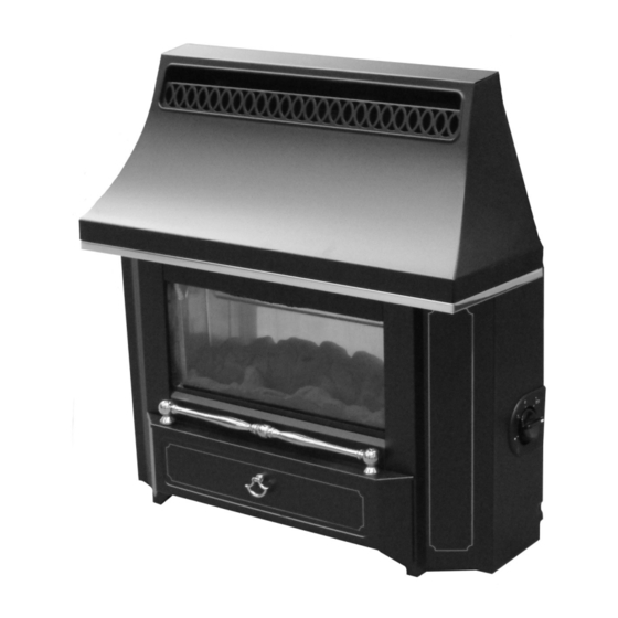
INSTALLATION AND OWNER GUIDE
Model 341
Black Beauty Slimline
LIVE FUEL EFFECT GAS FIRE
(GC No. 32-032-30)
We trust that this guide gives
sufficient details to enable this
appliance to be installed and
maintained satisfactorily. However, if
further information is required, our
Valor Fires Technical Helpline will
be pleased to help.
Telephone 0844 8711 565 (National
call rates apply in the United
Kingdom).
In the Republic of Ireland
Telephone 0044 844 8711 565.
INSTALLER: Please leave this guide with the owner
©
Baxi Heating U.K. Limited 2008.
600B690/14
Advertisement
Table of Contents

Related Manuals for Valor Fires 341 black beauty slimline


Summary of Contents for Valor Fires 341 black beauty slimline
- Page 1 However, if further information is required, our Valor Fires Technical Helpline will be pleased to help. Telephone 0844 8711 565 (National call rates apply in the United Kingdom).
- Page 2 Warning: Any person who does any unauthorised act in relation to a copyright work may be liable to criminal prosecution and civil claims for damages. Valor Fires, Erdington, Birmingham B24 9QP www.firesandstoves.co.uk Because our policy is one of constant development and improvement, details may vary slightly from those given in this publication ©...
- Page 3 Careful Installation Valor Fires is a CORGI registered company. All our gas fires must be installed by a competent CORGI Registered Installer in accordance with our Installer Guide and should not be fitted directly on to a carpet or floor of combustible material.
-
Page 4: Table Of Contents
CONTENTS Section Heading Page INSTALLER GUIDE 5 - 26 OWNER GUIDE 27 - 39 1 SAFETY 2 LIST OF ACCESSORIES 3 APPLIANCE DATA 4 GENERAL INSTALLATION REQUIREMENTS 4.11.2 Conventional fireplace. 4.11.3 Wall mounting to conventional or pre-cast flues. 4.11.4 Precast flues. 4.11.5 Metal flue box. -
Page 5: Installer Guide
INSTALLER GUIDE INSTALLER GUIDE FOR OWNER GUIDE SEE PAGES 27 TO 39 © Baxi Heating U.K. Limited 2008. Page 5... -
Page 6: Safety
INSTALLER GUIDE 1. SAFETY Installer Before continuing any further with the installation of this appliance please read the following guide to manual handling: The lifting weight of this appliance is 16.86 kg. One person should be sufficient to lift the fire. If for any reason this weight is considered too heavy then obtain assistance. - Page 7 INSTALLER GUIDE Natural (G20) Inlet Pressure 20mbar Control Setting 5.05kW (17,200 Btu/h) Gross Heat Input 3.45kW (11,800 Btu/h) 1.80kW (6,100 Btu/h) 1.55kW (5,300 Btu/h) 17.2 + 0.75mbar Burner Test Pressure (Cold) (6.9 + 0.3in w.g.) Gas Connection 8mm pipe Upper Cat.
-
Page 8: General Installation Requirements
INSTALLER GUIDE 4. GENERAL INSTALLATION REQUIREMENTS The installation must be in accordance with these instructions. For the user’s protection, in the United Kingdom it is the law that all gas appliances are installed by competent persons in accordance with the current edition of the Gas Safety (Installation and Use) Regulations. - Page 9 INSTALLER GUIDE Normal adventitious ventilation is usually sufficient to satisfy the ventilation requirements of this appliance. In GB reference should be made to BS 5871 Part 2 and in IE reference should be made to the current edition of IS 813 “Domestic gas Installations”...
- Page 10 INSTALLER GUIDE An extractor fan may only be used in the same room as this appliance, or in any area from which ventilation for the appliance is taken, if it does not affect the safe performance of the appliance. Note the spillage test requirements detailed further on in this manual.
-
Page 11: Conventional Fireplace
4.11 In the United Kingdom, as supplied, this appliance can be installed in the following situations: - Note: A spigot extension is available (Valor Fires part number 0595191). When fitted this shall extend through the closure plate for at least 15mm and have a minimum clearance of 50mm from the end to any surface. -
Page 12: Precast Flues
INSTALLER GUIDE 4.11.4 Precast flues. The appliance can be installed to a fireplace that has a properly constructed precast concrete or clay flue block system conforming to BS1289 or BS EN 1806. The appliance is suitable for installations conforming to older versions of BS1289 as well as the current standards. - Page 13 INSTALLER GUIDE found to be satisfactory. 4.12 If the fireplace opening is greater than the acceptable dimensions given in this guide, do not use the back of a fire surround or marble to reduce the opening. This may cause cracking of the surround back or marble. 4.13 The following flues are suitable: 225mm x 225mm conventional brick flue.
- Page 14 INSTALLER GUIDE 4.16 The front of the fireplace should be flat over an area sufficient to ensure a good seal with the closure plate. The flat surface should extend for a height equal to that of the closure plate plus 20mm and for a width equal to that of the closure plate plus 40mm.
-
Page 15: Pre-Installation Preparation
INSTALLER GUIDE 5. PRE-INSTALLATION PREPARATION 5.1 Unpacking. The carton contains the following:- 1off Fire assembly. 1off Ceramic fuel effect (In packaging inside firebox). 1off Closure plate. 1off Smoke match tube. 1off Olive & olive nut for gas line connection 1off Literature pack Remove all the items carefully to prevent damage. - Page 16 INSTALLER GUIDE 5.3.7. Remove the window unit by removing the screws each side of the window frame and lifting the unit clear. 5.3.8. Remove the ceramic fuel effect pack from the firebox and keep it safe. 5.3.9. Check ignition spark. Before attempting to install, it is worth checking that the piezo electric spark ignition system operates satisfactorily.
- Page 17 INSTALLER GUIDE 5.4.2 Wall mounting (See figure 10). The closure plate must be fitted and sealed to the hearth and fireplace opening using a suitable heat resistant material. If necessary cut the closure plate but make sure that it overlaps the fireplace opening sufficiently to allow satisfactory sealing.
-
Page 18: Appliance Installation
INSTALLER GUIDE Figure 10. Closure plate for wall mounting. 6. APPLIANCE INSTALLATION 6.1 Installing to a hearth. 6.1.1 Place the fire centrally on the hearth making sure that the spigot lines up with the spigot hole in the closure plate. Gently slide the appliance into place being careful not to scratch the hearth. -
Page 19: Gas Supply Connection
INSTALLER GUIDE 6.3 Gas supply connection. 8mm rigid tubing must be used to connect the gas supply to the appliance. An olive and nut are provided for connection to the inlet “T” connector on the appliance. The connector can be rotated to allow connection from either side or the rear. -
Page 20: Check Burner Pressure
INSTALLER GUIDE 7.1.6 Check all the control settings. These are:- Control Knob Burner appearance Position 1 / IGN Centre section on low. Outer sections off. Centre section fully on. Outer sections off. Centre section fully on. Outer sections on low. All sections fully on. -
Page 21: Flame Supervision And Spillage Monitoring System
This monitoring system must not be adjusted, bypassed or put out of operation. This monitoring system must only be exchanged using Valor Fires authorised parts. ©... -
Page 22: Final Assembly And Review
INSTALLER GUIDE 8. FINAL ASSEMBLY AND REVIEW Before fitting the fascia ensure that the information on the back pages of the owner guide have been completed. 8.1 Fitting the fascia. 8.1.1 Detach the control knob and control bezel. 8.1.2 Refit the fascia. The fascia top rear strip should locate in front of, but touching, the side extensions of the engine back panel (See figure 14). -
Page 23: Servicing And Parts Repacement
INSTALLER GUIDE 8.2.8 Advise that any cleaning must only be carried out when the fire is off and cold. 8.2.9 Advise the customer that they should read the owner guide before operating the fire and always follow the advice in the section headed "Cleaning your fire". 8.2.10 Advise the customer that the appliance will operate to its maximum potential if the flue is primed during the first 20 - 30 minutes of use. -
Page 24: To Remove The Window Unit
INSTALLER GUIDE 9.1 To remove the window unit. 9.1.1 Detach the window surround by sliding it upwards and then swinging the bottom forwards (See figure 6 in the installation section). Lift and store carefully. 9.1.2 Remove the window unit by removing the screws each side of the window frame and lifting the unit clear. -
Page 25: To Grease The Control Tap
INSTALLER GUIDE 9.6 To grease the control tap. 9.6.1 Detach the tap and remove the piezo generator as section 9.5 making sure that the tap is in the ‘off’ position. 9.6.2 Remove the two screws from the head of the tap. Remove the niting head and spindle complete with collar and spring. - Page 26 INSTALLER GUIDE required. 9.8.8 Replace in the reverse order. Note: 1. The pilot unit is an atmosphere sensing device. It must be replaced as a whole assembly. Its individual components are not separately replaceable. 2. If the pilot is removed, when refitting, make sure that the pilot heat shield is in place between the pilot unit and the rear of the burner and is the correct way round (See figure 16).
-
Page 27: Owner Guide
OWNER GUIDE OWNER GUIDE FOR WARRANTY AND SERVICE INFORMATION SEE PAGES 36 TO 39 © Baxi Heating U.K. Limited 2008. Page 27... - Page 28 OWNER GUIDE CONTENTS Section Page SAFETY APPLIANCE DIMENSIONS GAS CONSUMPTION OPERATING YOUR FIRE The Oxysafe flame sensing and flue blockage safety system. To light the fire. To turn the fire off. Lighting with a taper. CLEANING YOUR FIRE Metal parts. Window glass.
- Page 29 OWNER GUIDE SAFETY IF YOU SMELL GAS DON’T SMOKE. EXTINGUISH ALL NAKED FLAMES. DON’T TURN ELECTRICAL SWITCHES ON OR OFF. TURN OFF THE GAS SUPPLY AT THE METER. OPEN DOORS AND WINDOWS TO GET RID OF THE GAS. IMMEDIATELY CALL THE GAS EMERGENCY SERVICE FROM A NEIGHBOURS PHONE - SEE YOUR LOCAL TELEPHONE DIRECTORY.
- Page 30 OWNER GUIDE Graph 1. Combustible shelf clearances Do provide a minimum clearance of 100mm between the fascia sides and any corner wall having combustible material or other combustible surface which projects beyond the front of the fire (See figure 1). Please bear this in mind if ever you are considering altering the room.
- Page 31 OWNER GUIDE APPLIANCE DIMENSIONS See graph Figure 1 Dimensions and clearances GAS CONSUMPTION Has a maximum natural gas input of 5.1kW (Gross) Has a maximum natural gas output of 4.0kW Has a minimum natural gas input of 1.55kW (Gross) Has a minimum natural gas output of 1.0kW ©...
- Page 32 OWNER GUIDE OPERATING YOUR FIRE PLEASE NOTE When operating your fire for the first time, some vapours may be given off which may cause a slight odour and could possibly set off any smoke alarms in the immediate vicinity. These vapours are quite normal with new appliances. They are totally harmless and will disappear after a few hours use.
- Page 33 OWNER GUIDE The burner settings are: Control Knob Burner appearance Position 1 / IGN Centre section on low. Outer sections off. Centre section fully on. Outer sections off. Centre section fully on. Outer sections on low. All sections fully on. We recommend that the fire is set at position 4 for the first 10 minutes after lighting to warm up the chimney and so obtain full efficiency quickly.
- Page 34 OWNER GUIDE CLEANING YOUR FIRE To maintain the high performance and quality finish of your Valor Fires fire, please follow these guidelines: Before attempting to clean the fire, please remember to turn off the fire and wait for the appliance to cool. The fire will retain heat for some time before cleaning can begin.
- Page 35 OWNER GUIDE MAINTENANCE Regular maintenance. In order to achieve and maintain high levels of personal safety and performance efficiency, it is essential that the opening at the back of the fire and the flue are kept clear of any form of obstruction. It is possible that deposits of mortar or soot could fall and accumulate causing the flue to be blocked or restricted and so preventing proper clearance of dangerous exhaust fumes.
- Page 36 OWNER GUIDE What you need to do if you experience a problem with the operation of the fire: You should always contact your installer first, because the cause of the fault may not be related to the fire. If your installer confirms that the fault is with the fire and they can’t repair it, our friendly customer service team is on hand to help.
- Page 37 OWNER GUIDE © Baxi Heating U.K. Limited 2008. Page 37...
- Page 38 OWNER GUIDE Installer Details (Block Capitals) Installer Name Corgi Registration Number. Company Name. Company Address Company Telephone number Company Fax number © Baxi Heating U.K. Limited 2008. Page 38...
-
Page 39: Owner Guide
OWNER GUIDE Model Serial number (Can be found on the information label - See figure 6) A LABEL CONTAINING THE SERIAL NUMBER MAY HAVE BEEN PLACED INSIDE THIS BOX. Fascia name (Block Capitals) Fascia code - Can be found close to the information label (Block Capitals) A LABEL CONTAINING THE FASCIA CODE MAY HAVE BEEN PLACED INSIDE THIS BOX. - Page 40 © Baxi Heating U.K. Limited 2008.
Need help?
Do you have a question about the 341 black beauty slimline and is the answer not in the manual?
Questions and answers