Table of Contents
Advertisement
Service-Handbuch
Service Booklet
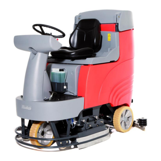
Scrubmaster B 115 R
(7090.11/21/35/41/51/81/91)
Schulung/Training
Fehlersuche/Troubleshooting
Einstelldaten/Adjustments
.
.
.
Hako GmbH
Technisches Produktmanagement
D-23840 Bad Oldesloe
Stand 09/2014
Vertraulich – nur für den internen Gebrauch
For internal use only!
.
Foil 1
Advertisement
Table of Contents

Related Manuals for HAKO Scrubmaster B 115 R


Summary of Contents for HAKO Scrubmaster B 115 R
- Page 1 Service-Handbuch Service Booklet Scrubmaster B 115 R (7090.11/21/35/41/51/81/91) Schulung/Training Fehlersuche/Troubleshooting Einstelldaten/Adjustments Hako GmbH Technisches Produktmanagement D-23840 Bad Oldesloe Stand 09/2014 Vertraulich – nur für den internen Gebrauch For internal use only! Foil 1...
-
Page 2: Table Of Contents
Contents Information General Information 2.1 Settings 2.1.1 Connection with the Diagnosis-Computer 2.1.2 Flashing of the control unit 2.1.3 Connection schemes with the different interfaces 2.2 Short Description 2.2.1 Deactivating Vacuuming / Dirty Water Tank Full 2.2.2 Home Position of the Machine 2.2.3 Seat Contact Switch (3.6.6.4.) 2.2.4 Introduction to Programming 2.2.5 Reset Last Error Which Occurred in the Start Screen... - Page 3 Contents Maintenance Intervals 4.1 Hako System Maintenance (Customer) 4.2 Hako System Maintenance I 4.3 Hako System Maintenance II 4.4 Hako System Maintenance S Cleaning Programs Machine Settings 6.1 Basic Settings 6.1.1 Machine Type 6.1.2 Cleaning Units 6.1.3 Battery Setting 6.1.4 Charger 6.2 Settings On Customer Request (PPV)
- Page 4 Contents Mechanical Components 7.1 Squeegee 7.2 Disk Brush Head 7.3 Cylindrical Brush Head 7.3.1 Adjustment cylindrical brush head 7.4 Brush Head Lifting Unit 7.4.1 Potentiometer in the Brush Head Lifting Unit Water Pump 8.1 Water Quantities 8.2 Water Pump Standstill Recognition Drive Control Units 9.1 ATECH / ZAPI Drive control unit (DC-Motor) 9.1.1 Automatic Monitoring of Components...
- Page 5 Contents Error Reference Chart with Information on Service Display 10.1 Service Counter 3.3.1.1. Brakes 11.1 Adjustment of Brake (DC-Motor) 11.2 Brake of the AC Motor Options 12.1 Silence Kit 12.2 Acoustic Warning Signal 12.3 Chemical Dosage 12.4 Scrubbing-Vacuum Tool Real-Time Clock (RTC) Notes Foil 5...
-
Page 6: Information
1. Information Attention: • All work on the vehicle may only be completed after disconnection of the power supply (disconnect the battery plug) with the exception of the current and voltage measurements. • When changing high current fuses, only loosen the screws. Never unscrew the screws completely, otherwise there is a risk of short circuit. -
Page 7: General Information
2. General Information as part of a restyling of the Hako brand names, the name of the scrubber-driers has been changed from "Hakomatic" to "Scrubmaster". In this document both names are used equally, because this document is also valid for machines which have been... - Page 8 2. General Information B115 R The Scrubmaster B115 R is available with working widths between 65 cm and 90 cm. The 7090.35/41/51 models require an external charger; the 7090.11/21/81/91 models are equipped with an integrated charger. The 7090.51 model is equipped with a 65 cm disk brush unit; the 7090.11/35 models are equipped with a 75 cm disk brush unit.
-
Page 9: Settings
03502430) represent the hardware required. Windows XP or Windows 7 must be installed as the operating system on the PC. The diagnostics software required for the Scrubmaster B115R is contained on the current Hako Diagnosis CD-ROM (85-00- 2144). Foil 9... - Page 10 2.1 Settings A new machine control unit is delivered from spares stock without machine software. Only the Boot-loader is pre-installed on the control module. This can be recognized by the jumping “F” in the hour meter display of the dashboard, after the control module is mechanically and electrically installed in the machine and the keyswitch is switched “on”.
-
Page 11: Connection With The Diagnosis-Computer
• up to date Hako Diagnosis software (DVD 85-00-2144/xx) • Service computer (e.g. CF19 Hako order No. 03501860, english keyboard) • Interface PN 03501750* (as Software-License) or 03502430** (as Software- License and USB to RS232 (COM) converter) – works only at the B115 R as a converter USB to RS232 •... - Page 12 Benutzername / user name: Hako-Kunden Kennwort / Pass word: N3GRBX6M7PCT Alternative please download the latest revision of the diagnosis software from Hako- Download server. For information regarding the access to this download server, please ask Mrs. Maike Christiansen under e-mail: mchristiansen@hako.com To install the diagnosis software on a service computer: 1) Delete the folder "C:\HakoDiagnose"...
-
Page 13: Flashing Of The Control Unit
X3 of the machine control unit. - Switch on the power of the machine. - Run the Hako Diagnosis Software. Select the button "HAKO", then the button "Scrubmaster B115 R / Hakomatic B115 R". This will start the flashing tool for the Scrubmaster B115 R. - Page 14 2.1.2 Flashing of the control unit - Follow the instructions, key in the Hako-serial and do not disconnect the cable and / or switch off the computer or the machine before the job is completed. -The settings for options, battery type and parameter you can change by using the buttons on the operating panel with pluged diagnosis plug.
-
Page 15: Connection Schemes With The Different Interfaces
2.1.3 Connection schemes with different interfaces Configuration (1) with Interface PN 03501750 *: Configuration (2) with Interface PN 03502430 **: Foil 15... -
Page 16: Short Description
2.2 Short Description The vehicle is controlled by means of the following electronics: • Central electronics system (A1) • Operating and indicator panel (A2) • Drive control (A4) The control electronics (A1) assumes all the control and monitoring tasks in the vehicle except for the driving functions. -
Page 17: Deactivating Vacuuming / Dirty Water Tank Full
2.2.1 Deactivating Vacuuming / Dirty Water Tank Full Vacuuming is switched off manually by the operator using the corresponding button or automatically when the “Dirty water tank full” signal is received in order to protect the suction turbines. Deactivation by the operator: •... -
Page 18: Home Position Of The Machine
2.2.2 Home Position of the Machine After switching the machine on, all the components are set to their "home position" when the seat contact switch is actuated (closed). The lifting elements are raised as long as they have not been switched off by the microswitch monitoring the top end position integrated in the lifting element. -
Page 19: Seat Contact Switch (3.6.6.4.)
2.2.3 Seat Contact Switch (3.6.6.4.) The seat contact switch is connected to the control electronics A1 at A1:X9.8+18. The control electronics (A1) reacts to the opening of the seat contact switch with a 2- second delay. This means: if the contact is opened for longer than 2 seconds during operation, the motors stop and the brush head and squeegee are raised. - Page 20 2.2.3 Seat Contact Switch (3.6.6.4.) To reactivate the machine functions after the “seat contact switch manipulation” was triggered, the control system needs to recognize a change in switch position (ON-OFF-ON or OFF-ON-OFF). Sear contact closed means, the operator is on the seat; Seat contact open means, no operator is on the seat.
-
Page 21: Introduction To Programming
2.2.4 Introduction to Programming The Hakomatic B115R can be configured by means of the software and adapted to various options. The software is also used to adapt the machine to the various hardware (machine type, disk brush head or cylindrical brush head, batteries - TSG). The modification of parameters not described in this manual could lead to machine malfunction. - Page 22 2.2.4 Introduction to Programming A1.X3 Press and hold Buttons 1 and 2 simultaneously (Fig. 2.3) and switch on the key switch. The following display appears in the operating hour counter after approx. 3 seconds: Fig. 2.1 •The start screen of the Configuration menu is now open.
- Page 23 2.2.4 Introduction to Programming You can navigate through the Configuration menu using the three 3 buttons indicated on the operating panel. Button 3 Dashboard Button 1 is the "Water on/off " button; Button 2 the "Water +-" button; Button 3 the "Silent Mode"...
- Page 24 2.2.4 Introduction to Programming Press Button 1 to change the active level: Chapter -> Configuration -> Content -> Chapter Config- Chapter Content uration Press Button 2 to increase the value in the active level. After reaching the highest value, pressing again calls in the lowest value.
-
Page 25: Reset Last Error Which Occurred In The Start Screen
2.2.5 Reset Last Error Which Occurred in the Start Screen Access the programming level as described in Chapter 2.2.4. Fig. 2.1 appears. The diagnostics connector must be connected to A1.X3. Press Button 2 six times, the last error which occurred is indicated in the display. e.g. Press and hold Button 3 for approx. -
Page 26: Technical Data
Technical Data Foil 26... - Page 27 Technical Data Foil 27...
- Page 28 Technical Data Foil 28...
-
Page 29: Maintenance Intervals
Hako System Maintenance I: (every 250 hours of operation) To be performed by qualified personnel of authorised Hako Service Centre in accordance with the machine-specific system maintenance including spare part kit. Hako System Maintenance II: (every 500 hours of operation) To be performed by qualified personnel of authorised Hako Service Centre in accordance with the machine-specific system maintenance including spare part kit. -
Page 30: Hako System Maintenance (Customer)
4.1 Hako System Maintenance K The daily and weekly maintenance intervals must be performed by the customer/operator. Foil 30... -
Page 31: Hako System Maintenance I
4.2 Hako System Maintenance I The following maintenance work must be performed by an authorised Hako Service workshop. Foil 31... -
Page 32: Hako System Maintenance
4.3 Hako System Maintenance II The following maintenance work must be performed by an authorised Hako Service workshop. Foil 32... -
Page 33: Hako System Maintenance S
4.4 Hako System Maintenance S (Safety Check) The following maintenance work must be performed by an authorised Hako Service workshop. (Only DC motor) Foil 33... -
Page 34: Cleaning Programs
Cleaning Programs (FPV) The cleaning programs define the behavior of the water supply to the brushes, the brush motors in respect of the position of the drive direction switch, the drive potentiometer (forwards, neutral, reverse) and the squeegee. The drive direction switch S07 and drive potentiometer switch S08 provide a 24 V signal for forward drive at input A01.X10:4 and for reversing at input A01.X10:5. - Page 35 5. Cleaning Programs (FPV) Contents Function Brush off when drive control is in neutral Brush off when drive control is in reverse Lift brush when drive control is in neutral Lift brush when drive control is in reverse Water off when drive control is in neutral Water off when drive control is in reverse...
- Page 36 5. Cleaning Programs (FPV) Description 99-7090-11 / 99-7090-81 / 99-7090-51 21 / 35 / 41 FPV Set Refer to FPV table Refer to FPV table Refer to FPV table Refer to FPV table Refer to FPV table Refer to FPV table Refer to FPV table Refer to FPV table Refer to FPV table...
-
Page 37: Machine Settings
6. Machine Settings 6.1 Basic Settings 6.1.1 Machine Type There are various model types, equipment installed and working widths regarding the machines in the Hakomatic B115R series. These types can be set in the Configuration menu. To check and change the machine type setting, access programming level as described in Chapter 2.2.4. - Page 38 6. Machine Settings 6.1 Basic Settings 6.1.1 Machine Type Description 99-7090-11 99-7090-81 99-7090-51 / 21 / 35 / / 91 Machine Model Hakomatic B115 / 650 (99.7090.51) Hakomatic B115 / 750 / 700 (99.7090.11/.21/.35/.41) Hakomatic B115 / 900 / 850 (99.7090.81/.91) Chart 6.1 Foil 38...
-
Page 39: Cleaning Units
6. Machine Settings 6.1.2 Cleaning Units Different brush units can be used with the Hakomatic B115R. Three disk brush units are available with working widths of 65 cm, 75 cm and 90 cm. Two cylindrical brush units with working widths of 70 cm and 85 cm are also available. This setting is necessary to ensure correct function of the overload limits and the water quantities. - Page 40 6. Machine Settings 6.1.2 Cleaning Units Description 99-7090-11 99-7090-81 99-7090-51 / 21 / 35 / / 91 Cleaning Units Disk brush 650 mm Disk brush 750 mm Disk brush 900 mm Cylindrical brush 700 mm Cylindrical brush 850 mm Chart 6.2 Foil 40...
-
Page 41: Battery Setting
6. Machine Settings 6.1.3 Battery Setting (TSG - total discharge signal transducer) In order to achieve the optimum operating time for the machine with the batteries installed and optimum service life of the batteries, it is essential to set the battery monitor, referred to as TSG, to the correct discharge curve. - Page 42 6. Machine Settings 6.1.3 Battery Setting (TSG - total discharge signal transducer) GiS and GiV are flat plate batteries, PzS and PzV are tube plate batteries GiV and PzV are sealed, absolutely maintenance-free gel batteries GiS and PzS are sealed, low-maintenance batteries with liquid electrolyte. AGM batteries are wrapping electrodes with fiberglass separators.
- Page 43 6. Machine Settings 6.1.3 Battery Setting (TSG - total discharge signal transducer) Description 99-7090-11 99-7090-81 99-7090-51 / 21 / 35 / / 91 Battery Setting Crown without offset Crown with offset GIS, "foreign" PzS, "foreign" Hoppeke AGM with offset Chart 6.3 Foil 43...
-
Page 44: Charger
6. Machine Settings 6.1.4 Charger This menu option is used to define whether the machine is equipped with an integrated charger. This adjustment is necessary so that the TSG can operate correctly. To check and change the machine type setting, access programming level as described in Chapter 2.2.4. - Page 45 6. Machine Settings 6.1.4 Charger Description 99-7090-11 99-7090-81 99-7090-51 / 21 / 35 / / 91 Chargers Charger not available Charger available Chart 6.4 Foil 45...
-
Page 46: Settings On Customer Request (Ppv)
6. Machine Settings 6.2 Settings On Customer Request The programmable program versions can be used to complete various settings on the machines. E.g. it is possible to program whether the last error which occurred on the machine should be displayed or not when the machine is switched on again. To check and change the PPV setting, access programming level as described in Chapter 2.2.4. - Page 47 6. Machine Settings 6.2 Settings On Customer Request Description 99-7090-11 / 99-7090-81 / 99-7090-51 21 / 35 / 41 "Last error" indicator after switching on the machine Deactivate Activate Water level when switching on scrubbing Last setting Preset level (4) Chart 6.5/1 Foil 47...
- Page 48 6. Machine Settings 6.2 Settings On Customer Request Description 99-7090-11 / 99-7090-81 / 99-7090-51 21 / 35 / 41 Water level when switching on scrubbing and vacuuming Last setting Preset level Water level when switching on TOOL (menu option only appears when TOOL option is activated!) Last setting Preset level (4)
- Page 49 6. Machine Settings 6.2 Settings On Customer Request Description 99-7090-11 / 99-7090-81 / 99-7090-51 21 / 35 / 41 Water Setting From last level to first level (in circuit) Change direction on reaching max./min. level (ping-pong) Silence Mode Setting (menu option only appears when Silence Mode option is activated!) Is not saved...
- Page 50 6. Machine Settings 6.2 Settings On Customer Request Description 99-7090-11 / 99-7090-81 / 99-7090-51 21 / 35 / 41 Acoustic Alarm Tone Interval (menu option only appears when the Acoustic Alarm option is activated!) Standard Alternative Chart 6.5/4 Foil 50...
-
Page 51: Mechanical Components
7. Mechanical Components 7.1 Squeegee Fig. 7.1 Foil 51... - Page 52 7. Mechanical Components 7.1 Squeegee Adjustment / Angular adjustment of the sealing strips The angle adjustment is the decisive factor in ensuring the squeegee's sealing strips lie evenly on the floor. 1. Park the machine on a level surface and lower the squeegee. 2.
- Page 53 7. Mechanical Components 7.1 Squeegee Fig. 7.3 Fig. 7.2 Foil 53...
- Page 54 7. Mechanical Components 7.1 Squeegee Height adjustment The height adjustment is set to 3 mm at the factory. If, despite an optimum angle adjustment, streaks are produced, the distance between the rollers and floor must be adjusted by altering the number of washers (Fig. 7.1/6 / Fig. 7.3) on the holder. In the case of very smooth floors, e.g.
- Page 55 7. Mechanical Components 7.1 Squeegee Squeegee connection The drawing (Fig 7.4) specifies the dimensions for adjusting of the suspension springs (60 mm) and the threaded rods for adjusting the parallel alignment (151 mm) of the squeegee connection. Fig. 7.4 Foil 55...
-
Page 56: Disk Brush Head
7. Mechanical Components 7.2 Disk Brush Head Disk brush heads in 3 different working widths are available for the Hakomatic B115R; 65 cm, 75 cm and 90 cm. The two brushes are each driven by a separate motor. 7.3 Cylindrical Brush Head Cylindrical brush heads are available for the Hakomatic B115R in 2 different working width;... -
Page 57: Adjustment Cylindrical Brush Head
7. Mechanical Components 7.3.1 Adjusting the cylindrical brush head Adjusting the cylindrical brush head Produce a distance of 30 mm between the cylindrical brush head and ground by inserting the spacer blocks from the adjustment kit PN 01078870 at the left and right on the brush head (Fig. - Page 58 7. Mechanical Components 7.3.1 Cylindrical Brush Head Fig. 7.7 Fig. 7.8 Fig. 7.9 Foil 58...
-
Page 59: Brush Head Lifting Unit
7. Mechanical Components 7.4 Brush Head Lifting Unit Foil 59... - Page 60 7. Mechanical Components 7.4 Brush Head Lifting Unit Foil 60...
- Page 61 7. Mechanical Components 7.4 Brush Head Lifting Unit Foil 61...
-
Page 62: Potentiometer In The Brush Head Lifting Unit
7. Mechanical Components 7.4 Brush Head Lifting Unit 7.4.1 Potentiometer in the Brush Head Lifting Unit The potentiometer of the lifting element is powered by a 2.5 V reference voltage at A1.X19:1. Reference point for this voltage is A1.X19:3. Depending on the position of the potentiometer, the voltage at A1.X19:2 is between 0 and 2.5V. -
Page 63: Water Pump
8. Water Pump To control the function of the water pump, the voltage for the individual levels can be disconnected at the central electronics unit (A1.X11:4+11). The following results are achieved when measuring with a True RMS measuring instrument and water in the tank but with the suction turbines switched off: Disk brush Cylindrical brush... -
Page 64: Water Quantities
Water Quantities Measuring the water quantities provides a good, reliable method with which to check the function of the water pump. Let the pump run and measure the volume of water fed per minute (l/min.). The data regarding the water quantities is specified as follows in the operating manual: Stage Plate-... -
Page 65: Water Pump Standstill Recognition
Water Pump Standstill Recognition If the pump does not supply water to the brushes due to clogging of the hoses, the so-called standstill recognition is activated. Automatic standstill recognition for water pump: The electronic module allows protection of the water pump if the pump does not deliver correctly. -
Page 66: Drive Control Units
Drive Control Units The drive control is provided with its own diagnosis and self-test. Therefore, the function of the drive control is inhibited when the machine is switched on if the drive potentiometer is not in its neutral position or is not detected as being in neutral. -
Page 67: Atech / Zapi Drive Control Unit (Dc-Motor)
Drive Control Units 9.1 ATECH / ZAPI – DC Motor The ZAPI drive control unit is equipped with a diagnosis connector. Any changes of the factory presetting values and parameters is forbidden. Position of connectors A = Connector for relay control and control inputs B = Connector for diagnosis device and alarm LED Foil 67... - Page 68 Drive Control Units 9.1 ATECH / ZAPI – DC Motor Connectors, Description of ZAPI Drive Control Speed reduction no 1 input; normally close contact toward battery positive: active when pin is free. Europe quick inversion input; normally open contact; active when pin is connected to battery positive. Tiller or seat micros witches;...
-
Page 69: Automatic Monitoring Of Components
Drive Control Units 9.1 ATECH / ZAPI – DC Motor 9.1.1 Automatic Monitoring of Components The micro-processor executes evaluation of basic controller functions. This evaluation concerns the following 4 states: •Check upon switching on by key switch: Watchdog, current sensor, power MOS FETs, contactor drive (contactor driver), direction switch, potentiometer connections, EEPROM •Check during standstill: Watchdog, current, power MOS FETs, contactor drive (contactor driver), potentiometer... -
Page 70: Diagnosis Led For Drive Module (Zapi)
Drive Control Units 9.1 ATECH / ZAPI – DC Motor 9.1.2 Diagnosis LED for Drive Module (ZAPI) Flash-Code Message Status* Remark WATCH-DOG Faulty electronic 2/3/4/5) EEPROM Faulty electronic (EEprom) INCORRECT START Direction selected when switching on (or incorrect IR connection) VMN LOW MOSFET short-circuited VMN HIGH... -
Page 71: Explanations Of Error Messages
Drive Control Units 9.1 ATECH / ZAPI – DC Motor 9.1.3 Explanations of Error Messages 1) WATCH-DOG Test in rest position as well as during riding; internal auto-test function of hard- and software; replace controller in case of error alarm! 2) EEPROM PAR. - Page 72 Drive Control Units 9.1 ATECH / ZAPI – DC Motor 4) EEPROM DATA KO Data in the memory area which controls the hourmeter are faulty. If alarm disappears, after switching key switch off and on, mind the fact that the hourmeter is reset to zero.
- Page 73 Drive Control Units 9.1 ATECH / ZAPI – DC Motor 6) INCORRECT START Incorrect sequence of start conditions. Depending on SAFETY SWITCH programming, system starts if the following sequence is respected: - key switch – handle micro-switch – direction switch (HANDLE) - key switch - direction switch(FREE) - key switch + seat contact switch - direction switch (SEAT) Possible causes:...
- Page 74 Drive Control Units 9.1 ATECH / ZAPI – DC Motor 7) VMN LOW Test in rest state and during ride until VMN is pulsed out to up to 80%; If contactors are open, voltage at VMN connection normally amounts to 50% VBatt. If this voltage value is insufficient (<...
- Page 75 Drive Control Units 9.1 ATECH / ZAPI – DC Motor 8) VMN HIGH Test in rest state; If contactors are open, voltage at VMN connection normally amounts to 50% VBatt. If this voltage value is exceeded (> 70% VBatt), an alarm is output. Possible causes: a) A direction contactor is permanently closed since mechanically blocked or permanently driven (incorrect wiring of contactor coil) b) Short-circuit between field and armature winding of motor...
- Page 76 Drive Control Units 9.1 ATECH / ZAPI – DC Motor 9) VACC NOT OK Test in rest state; Alarm is displayed if, referred to the saved minimum value, potentiometer voltage is higher than 1V. Possible causes: a) Wire broken at potentiometer or inductive sensor. b) Potentiometer or the inductive sensor is defective.
- Page 77 Drive Control Units 9.1 ATECH / ZAPI – DC Motor 11) HIGH CURRENT Test in rest state – contactor open; If measured current is >50A, alarm is output and the system switches off. The current sensor is defective (replace controller!) 12) PEDAL WIRE KO If no voltage is measured at pin NPOT (A12), to which the negative wire of the potentiometers is connected, an alarm is output.
- Page 78 Drive Control Units 9.1 ATECH / ZAPI – DC Motor 13) TEMPERATURE This message signals that controller temperature has exceeded 76°C. Maximum current is reduced step by step to zero at a temperature of 86°C. Possible causes: a) If the alarm is output immediately after system ON with cold controller, temperature monitoring is faulty (replace controller!) b) If the alarm is output after relatively short period of operation,heat is insufficiently dissipated (check installation and fixing screws)
- Page 79 Drive Control Units 9.1 ATECH / ZAPI – DC Motor 15) DRIVER 1 KO If voltage at connection NT1 (A11) does not correspond to determined value, an alarm is output and the system switches off. Possible causes: a) Wire broken at connection NT1 (A11) or coil of reverse direction contactor is defective.
- Page 80 Drive Control Units 9.1 ATECH / ZAPI – DC Motor 17) DRIVER 2 KO If voltage at connection NT2 (A4) does not correspond to determined value, an alarm is output and the system switches off. Possible causes: a) Wire broken at connection NT2 (A4) or coil of forward direction contactor is defective.
- Page 81 Drive Control Units 9.1 ATECH / ZAPI – DC Motor 19) DRIVER SHORTED (only H0 STANDARD TRACT.) If voltage at connection NT1 (A11) does not correspond to determined value, an alarm is output and the system switches off. Possible causes: a) Wire broken at connection NT1 (A11) or coil of forward or reverse direction contactor is defective.
- Page 82 Drive Control Units 9.1 ATECH / ZAPI – DC Motor When does First test Result Second test Result Error error occur? --> --> Forward direction In forward contactor closes for 0.3 direction only At the forward direction contactor, a sec. before opening voltage applies to the coil for 0.3 sec.
- Page 83 Drive Control Units 9.1 ATECH / ZAPI – DC Motor The make contact of the forward direction contactor (TA) or the break contact of the reverse direction contactor (TI) is soiled or blocked. Clean contacts or, if required, replace contactor group. Clean the make contact of forward direction...
- Page 84 Drive Control Units 9.1 ATECH / ZAPI – DC Motor The break contact of the forward direction contactor (TA) or the make contact of the reverse direction contactor (TI) is soiled or blocked. Clean contacts or, if required, replace contactor group. Clean the make contact of reverse Clean the break...
- Page 85 Drive Control Units 9.1 ATECH / ZAPI – DC Motor No connection to motor: - Carbon brushes without contact to collector (Fig. 1) - Connection cable of carbon brushes interrupted (Fig. 2) - Motor winding defective or motor cable interrupted - Incorrect connection of motor Foil 85...
- Page 86 Drive Control Units 9.1 ATECH / ZAPI – DC Motor B1 The forward direction contactor is correctly driven but does not close. - Contactor coil is defective; use ohmmeter to measure resistance - Contact is mechanically blocked - Nominal voltage of contactor coil higher than battery voltage B2 The reverse direction contactor is correctly driven but does not close.
- Page 87 Drive Control Unit 9.1 ATECH / ZAPI – DC Motor 21) POSITION HANDLE If upon switching on, the handle micro-switch has already been actuated, error is signalled (only if SAFETY SWITCH is programmed to HANDLE). Possible causes: a) Handle micro-switch stuck b) Incorrect operation 22) INVERSION If upon switching on, the emergency reverse (deadman) button is depressed, an alarm...
-
Page 88: Dmc (Ac-Motor)
Drive Control Unit 9.2 DMC – AC Motor The DMC-drive control unit is equipped with a diagnosis connector. If not explicitely stated in the service manuals, a change of the factory preset parameters and values is forbidden. Currently only the diagnosis with the blinking codes at the Trip-LED is used for the Drive control unit. - Page 89 Drive Control Unit 9.2 DMC – AC Motor A1 – Forward switch (activ, if B- is present) A2 – Reverse switch (activ, if B- is present) A3 – enable drive mode from switch –S08 (activ, if B- is present) A4 – enable drive mode from machine control unit (Seat contact switch) (activ, if B- is present) A5 –...
-
Page 90: Error-Codes On The Dmc Control Unit (Ac Motor)
Drive Control Unit 9.2.2 Error codes DMC Control Unit – AC Motor – Diagnosis Overview DMC PAC212TS01 Hako B115R Action Calibrator Message Description Error Messages – LED Blinking Code Warning Faults None No action required Controller operational and OK (lowest Priority) - Page 91 Drive Control Unit 9.2.2 Error codes DMC Control Unit – AC Motor Calibrator Message Description Action Error Messages – LED Blinking Code Warning Faults Thermal cutback, allow the motor to cool Use vehicle within it‟s Motor hot down specifications Thermal cutback, allow the controller to Check heat sinking and Controller hot cool...
- Page 92 Drive Control Unit 9.2.2 Error codes DMC Control Unit – AC Motor Action Calibrator Message Description Error Messages – LED Blinking Code Warning Faults Internal supply voltage E-eprom cannot be E-eprom not accessible below12 volt. Call DMC if this accessed problem occurs M a i n F a u l t s (Recycle to neutral) Both forward and reverse selected.
- Page 93 Drive Control Unit 9.2.2 Error codes DMC Control Unit – AC Motor Action Calibrator Message Description Error Messages – LED Blinking Code Check battery capacity / charge level Voltage too low nternal 12V supply low. / controller voltage rating / settings not used Check battery capacity / charge level Voltage too low...
- Page 94 Drive Control Unit 9.2.2 Error codes DMC Control Unit – AC Motor Action Calibrator Message Description Error Messages – LED Blinking Code H a r d F a u l t s (Recycle key-switch) Hardware over current Hardware over current circuit active Check adjustments and motor setup (AC) Contactor coil short...
- Page 95 Drive Control Unit 9.2.2 Error codes DMC Control Unit – AC Motor Action Calibrator Message Description Error Messages – LED Blinking Code H a r d F a u l t s (Recycle key-switch) Current measurement Current measurement system faulty. Replace controller fault Low side Mosfet...
-
Page 96: Error Reference Chart With Information On Service Display
Error Reference Chart with Information on Service Display Error number / Error source Comment Message number Check temperature of brush motors; check power consumption of brush motors; check cabling of thermostatic switch (connector X3 and X4) of 1.2.5.2. Thermostatic switch, brush 1/2 brush motors (series circuit). - Page 97 Error Reference Chart with Information on Service Display Error number / Error source Comment Message number 3.1.6.E. Power fuses (group signal) Group signal, fuses -F02; -A01.F2 Message appears after the "Last error" display 3.2.6.5. Backup battery "weak" and before the operating hour counter; remains 5 s or when working unit is ON Message appears after the "Last error"...
- Page 98 Error Reference Chart with Information on Service Display Error number / Error source Comment Message number Overload of small consumers (solenoid valve, 3.3.6.2. Group signal, low power outputs buzzer) 3.4.1.1. Drive rheostat Check drive direction switch and cabling Check thermostatic switch and cabling of drive 3.4.5.1.
- Page 99 Error Reference Chart with Information on Service Display Error number / Error source Comment Message number Check connection cable for control unit (-A01) - 4.5.2.5. Operating panel not detected operating panel (-A02). This error only occurs when switching the machine on Check connection cable for control unit (-A01) - Operating panel response 4.5.3.5.
- Page 100 Activation or deactivation and reset of the service interval is possible only with the Hako-Diagnosis System. This requests the same preconditions like the flashing of a new control unit: • Service-Computer with up to date Hako-Diagnosis-Software (and COM-Port) • Interface PN 03501750 or PN 03502430 •...
-
Page 101: Service Counter
10.1 Service-Intervall – 3.3.1.1 Establish a connection between the Service-Computer and the machine contro pcb and start the start the diagnosis software. Click on the tab „System“ of the diagnosis menu and choose „Write event“(Fig. 10.1). Fig.10.1 Then the window for the service interval is opened (Fig. 10.2). There the Service alert can deactivated with the button „Switch Off service alert“, or switched On or restarted with the button „Set Service alert to 365/250“. - Page 102 10.1 Service-Intervall – 3.3.1.1 Fig.10. 2 Foil 102...
-
Page 103: Brakes
11. Brakes The brake needs to be able to stopp the machine within 0.19 m per km/h on plane ways. At a maximum speed of 6.5 km/h this means, that the maximum stopping distance may be 1.235 m. This has to be checked after working on the brake system and during the regular maintenances. -
Page 104: Adjustment Of Brake (Dc-Motor)
11. Brakes 11.1 Adjustment of Brake (DC-Motor) Foil 104... -
Page 105: Brake Of The Ac Motor
11. Brakes 11.2 AC-Motor The AC-motor has got a magnetic brake, which is directly installed on the motor shaft. If the machine is not in a driving mode, the brake is active. The machine can only be pushed, if the key switch of the machine is „on“ and as long as the unlock button (1) is pressed. -
Page 106: Options
Options The following options are available for vehicles in the Hakomatic B115R series: •Silence kit (99.7730.10) •Acoustic warning signal (99.7091.00) •Chemical dosage (99.7678.45) •Scrubbing-vacuum tool (99.7376.02) Foil 106... -
Page 107: Silence Kit
12.1 Option, Silence Kit To activate the Silence Kit option, access the programming level as described in Chapter 2.2.4. Then define the parameter settings as indicated in the table below and save the settings. Description 99-7090-11 / 99-7090-81 / 99-7090-51 21 / 35 / 41 Silence Kit Not available... - Page 108 12.1 Option, Silence Kit Foil 108...
- Page 109 12.1 Option, Silence Kit Foil 109...
-
Page 110: Acoustic Warning Signal
12.2 Option, Acoustic Warning Signal To activate the Acoustic Warning Signal option, access the programming level as described in Chapter 2.2.4. Then define the parameter settings as indicated in the table below and save the settings. The switching contact of the cable harness is connected to connector -X10 on cable harness W3. -
Page 111: Chemical Dosage
12.3 Option, Chemical Dosage To activate the Chemical Dosage option, access the programming level as described in Chapter 2.2.4. Then define the parameter settings as indicated in the table below and save the settings. Description 99-7090-11 / 99-7090-81 / 99-7090-51 21 / 35 / 41 Chemical Dosing System Not available... - Page 112 12.3 Option, Chemical Dosage Foil 112...
- Page 113 12.3 Option, Chemical Dosage Foil 113...
- Page 114 12.3 Option, Chemical Dosage Foil 114...
- Page 115 12.3 Option, Chemical Dosage Foil 115...
- Page 116 12.3 Option, Chemical Dosage Foil 116...
- Page 117 12.3 Option, Chemical Dosage Foil 117...
- Page 118 12.3 Option, Chemical Dosage Foil 118...
- Page 119 12.3 Option, Chemical Dosage Foil 119...
- Page 120 12.3 Option, Chemical Dosage Foil 120...
- Page 121 12.3 Option, Chemical Dosage Foil 121...
- Page 122 12.3 Option, Chemical Dosage Foil 122...
-
Page 123: Scrubbing-Vacuum Tool
12.4 Option, Scrubbing-Vacuum Tool To activate the Scrubbing-Vacuum Tool option, access the programming level as described in Chapter 2.2.4. Then define the parameter settings as indicated in the table below and save the settings. Description 99-7090-11 / 99-7090-81 / 99-7090-51 21 / 35 / 41 TOOL Not available... - Page 124 12.4 Option, Scrubbing-Vacuum Tool Foil 124...
- Page 125 12.4 Option, Scrubbing-Vacuum Tool Foil 125...
- Page 126 12.4 Option, Scrubbing-Vacuum Tool Foil 126...
- Page 127 12.4 Option, Scrubbing-Vacuum Tool Foil 127...
-
Page 128: Real-Time Clock (Rtc)
13. Real-Time Clock (RTC) The Hakomatic B115R is equipped with a real-time clock which is integrated in the vehicle's control system. When the Dashboard vehicle is switched off, the clock is supplied with power from a backup Button 5 battery on the control electronics. Proceed as follows to set the clock, e.g. - Page 129 13. Real-Time Clock (RTC) •In order to access the Setup menu, press and hold Button 1 and Button 2 simultaneously while the key switch is switched on. After approx. 3 seconds, the year setting appears in the operating hour counter. (In the example, 11 for 2011).
- Page 130 •After pressing Button 5 for three seconds, the adjusted value is saved and the point at the bottom right behind the number reappears. •Exit from the menu by switching the engine off. •The settings can also be set using the HAKO diagnostics system. Foil 130...
-
Page 131: Notes
14. Notes Foil 131... - Page 132 14. Notes Foil 132...
- Page 133 14. Notes Foil 133...
Need help?
Do you have a question about the Scrubmaster B 115 R and is the answer not in the manual?
Questions and answers