Table of Contents
Advertisement
Advertisement
Table of Contents

Summary of Contents for Stocksbro AB Bio-Sol P4 GB 2,5
- Page 1 Manual for the Manual for the Bio-Sol furnace Bio-Sol furnace...
-
Page 2: Modell P4 Gb 2,5
Manual for the Bio-Sol furnace. Modell P4 GB 2,5 1. Preface Thank you for placing your order with us to deliver a Bio-Sol furnace to you. We know that you will be pleased with your choice and that with our system you will have a very economic, environmentally friendly and easily operated system. -
Page 3: Table Of Contents
Table of contents Chapter Pages Modell P4 GB 2,5 ..................... 2 1. Preface ........................2 2.Table of contents ....................3 3.Presentation ......................4 4.General safety rules ....................5 5.Operating controls/instruments ................5 6.The furnace’s function ................... 5 7.Installation ......................7 8.Operation and maintenance ................ -
Page 4: Presentation
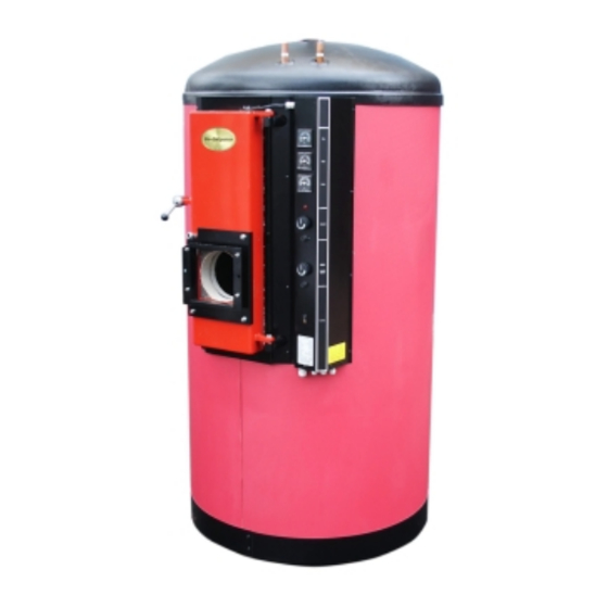
Presentation 3.1. The furnace The Bio-Sol furnace has a unique solution where the pellet furnace and accumulator have been integrated into a compact unit. The furnace can work with pellets, oil, solar and electrical energy. The furnace has a cylindrical standing accumulator tank with a biomass fuel furnace built into the upper part. In the tank there are loops to receive solar heating and to produce hot water. -
Page 5: General Safety Rules
General safety rules 4.1. Safety rules in general The furnace is designed for pellet burning combined with electrical and solar heating. The maximum operating pressure is 2.5 bar not to be exceeded. The normal operating temperature is 75 - 80ºC and the maximum temperature is 100ºC. The maximum temperature must not be exceeded. - Page 6 6.2. Heat radiator circuit Normal arrangement: The feed outlet is on the top of the furnace side (top feed). This should be coupled to the ventilating valve, safety valve, shunt valve and circulation pump for further transport to the radiators in the house. The expansion vessel connected to the lower connection point should be dimensioned for the system’s total water volume.
-
Page 7: Installation
In our proposed connection how connections can assembled for elimination of calcium through circulation of calcium elimination liquid through the loops is also given. 6.4. Solar heating. The solar heating loop is assembled in the furnace’s cold lower part, in parallel with the lower warm water loop. Through this arrangement effective possibilities are created to make use of the solar energy from the solar panels. - Page 8 Tips for handling the furnace during installation Use the wrapping that comes with the furnace. Saw, hammer and nails and one tension strap are the tools that are needed. Remove the furnace isolation. Leave the fittings and the instrument panel on the front.
- Page 9 7.2. Erection and assembly of the insulation. Put the furnace in place on a permanent and hard support and align it so that it stands vertically. Take into consideration the load carrying capacity where the furnace stands. The completely assembled furnace with water weighs about 1,000 kg.
- Page 10 Assembly of insulation on Bio-Sol furnace The furnace ready for assembly of the three part insulation The two halves are pressed together by a transport strap. N.B.! the protector under the tightening winch. Be careful that the grooves in the insulation halves fit into each other well.
- Page 11 7.3. Assembly of connections Pipe connections: • Assemble the pipe connections for heating and hot water and any solar heating. Connection to the copper pipes is done with clamp ring connections whereby the risk of heating the factory solder joints is eliminated. Alternatively solder joints can be made.
- Page 12 • If the connection of the chimney pipe is to go backward the uninsulated start piece can be used and its length adapted to the brickwork in the house’s chimney. • If the chimney is to be connected on any of the upward alternatives, an insulated start module should be assembled right or left.
-
Page 13: Operation And Maintenance
Operation and maintenance 8.1. Adjustment Furnace: Adjustment of the furnace takes place using the turbolators that are delivered as standard. The furnace is very efficient and the temperature of the smoke gases can therefore become so low that moisture from the smoke gases condenses out in the chimney. - Page 14 by screwing down the weights against each other. The target value for normal houses is 15 - 20 Pa. Burner and metering apparatus: See the respective manufacturer’s manual. 8.2. Running operation and maintenance Operation and maintenance of the furnace is limited to cleaning the soot and removal of ashes and checking the operating temperature and water levels and pressures in the furnace.
-
Page 15: Specifications
Specifications 9.1. Volumes, pressure and temperature Tank volume 630 litres Maximum operating pressure 1.5 bar Normal working temperature 75 - 80 ºC Maximum temperature 100 ºC Maximum power 25 kW 9.2. Materials Hot water loops 2, D 22 mm 12 m (in series) Solar loop 1, D 18 mm 12 m Steel plate, furnace... -
Page 16: Drawing Boiler
Drawing Boiler Utg. 19 Page 16... -
Page 17: Electrical Drawing Pellx 6 Kw Ep
Electrical Drawing PellX 6 kW EP Utg. 19 Page 17... -
Page 18: Electrical Drawing Pellx 3 Kw Ep
Electrical Drawing PellX 3 kW EP Utg. 19 Page 18... -
Page 19: Drawing System Bio-Sol
Proposal to system. Notice! The drawing is not complete in all details. Sensor Termal Cut-Out Sensor pellet burner PellX To radiators Sensor Oil/gasburner/Iwabo burner Warm Water Sensor Immersion heater Sensor Termal Cut-Out Immersion heater Return from radiators Alternative without sunenergy or under the wintertime Cold water Boiler System P4 GB... -
Page 20: Declaration
Declaration Utg. 19 Page 20... -
Page 21: Guarantee & Installation Certificate
Customer copy GUARANTEE & INSTALLATION CERTIFICATE Installed products: Furnace: The Bio-Sol furnace Burner: --------------------------------------------------------- Solar panels --------------------------------------------------------- Other optional equipment --------------------------------------------------------- Production number: --------------------------------------------------------- Installation date: --------------------------------------------------------- Installed at: --------------------------------------------------------- Name --------------------------------------------------------- Address --------------------------------------------------------- Mailing address --------------------------------------------------------- Telephone/fax --------------------------------------------------------- E-mail --------------------------------------------------------- Installer: ---------------------------------------------------------... -
Page 23: Guarantee & Installation Certificate
To be sent to Stocksbro Energi AB GUARANTEE & INSTALLATION CERTIFICATE Installed products: Furnace: The Bio-Sol furnace Burner: --------------------------------------------------------- Solar panels --------------------------------------------------------- Other optional equipment --------------------------------------------------------- Production number: --------------------------------------------------------- Installation date: --------------------------------------------------------- Installed at: --------------------------------------------------------- Name --------------------------------------------------------- Address --------------------------------------------------------- Mailing address --------------------------------------------------------- Telephone/fax ---------------------------------------------------------...
Need help?
Do you have a question about the Bio-Sol P4 GB 2,5 and is the answer not in the manual?
Questions and answers