Table of Contents
Advertisement
Quick Links
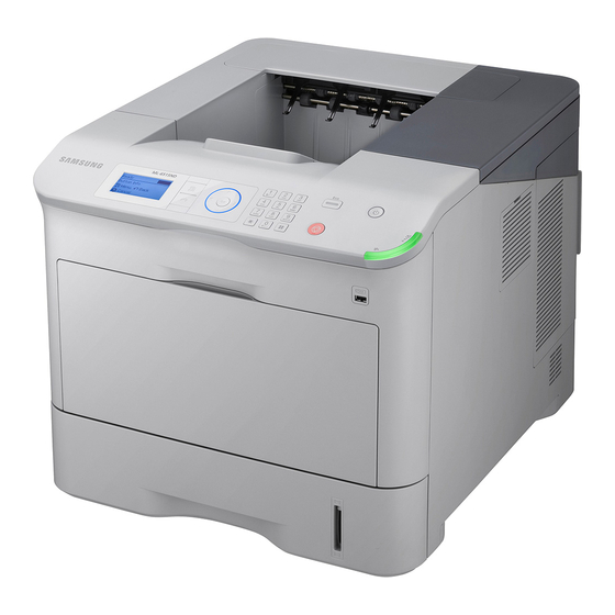
1. Speed
• ML-551x series : 55 ppm in Letter
• ML-651x series : 65 ppm in Letter
2. Printing Resolution
• Max. 1200x1200 dpi effective output
3. Processor
• SPGPV4 700 Mhz
4. Printer Language Emulations
• PCL, PS3
Service Manual
Mono Laser Printer
ML-551x/651x Series
5. Memory
• 256 MB default
• 256 MB / 512 MB (Optional Memory)
6. Interfaces
• One USB port, Two USB Host Port
• 1 GB Ethernet
• One IEEE 802.11 b,g,n wireless LAN (Optional)
7. Various optional units
• Finisher, Mailbox, SCF, HCF, HDD etc.
Advertisement
Table of Contents
Troubleshooting

Related Manuals for Samsung ML-651x series


Summary of Contents for Samsung ML-651x series
-
Page 1: Service Manual
1. Speed 5. Memory • ML-551x series : 55 ppm in Letter • 256 MB default • ML-651x series : 65 ppm in Letter • 256 MB / 512 MB (Optional Memory) 2. Printing Resolution 6. Interfaces • Max. 1200x1200 dpi effective output •... - Page 2 GSPN (Global Service Partner Network) North America : service.samsungportal.com Latin America : latin.samsungportal.com CIS : cis.samsungportal.com Europe : europe.samsungportal.com ⓒ Samsung Electronics Co.,Ltd. April. 2010 China : china.samsungportal.com Printed in Korea. Asia : asia.samsungportal.com Mideast & Africa : mea.samsungportal.com VERSION NO. : 1.00...
-
Page 3: Table Of Contents
Contents chapter 1 Precautions 1.1 Safety Warning …………………………………………………… 1-1 1.2 Caution for safety ………………………………………………… 1-2 1.2.1 Toxic material ………………………………………………… 1-2 1.2.2 Electric Shock and Fire Safety Precautions ……………… 1-2 1.2.3 Handling Precautions ……………………………………… 1-3 1.2.4 Assembly / Disassembly Precautions ……………………… 1-3 1.2.5 Disregarding this warning may cause bodily injury ………... - Page 4 Contents 3.3 Replacing the maintenance parts ……………………………… 3-4 3.3.1 Fuser unit …………………………………………………… 3-4 3.3.2 Pick up/Retard/Forward roller ……………………………… 3-5 3.3.3 Transfer roller ………………………………………………… 3-6 3.4 Replacing the main svc part …………………………………… 3-7 3.4.1 Cover ………………………………………………………… 3-7 3.4.2 Video controller ……………………………………………… 3-11 3.4.3 Engine controller ……………………………………………...
- Page 5 Contents 3.3.8 Stacker Motor ……………………………………………… 3-35 3.6 Mail Box …………………………………………………………… 3-36 chapter 4 Alignment and Troubleshooting 4.1 Alignment and Adjustments ……………………………………… 4-1 4.1.1 Control Panel ………………………………………………… 4-1 4.1.2 Understanding The Status LED …………………………… 4-2 4.1.3 JAM Removal ……………………………………………… 4-3 4.1.4 Useful menu item for service ……………………………… 4-14 4.1.5 Periodic Defective Image …………………………………...
- Page 6 Contents 6.2.2 Service Parts ………………………………………………… 6-4 6.3 A4 ISO 19798 Standard Pattern ………………………………… 6-8 6.3.1 A4 ISO 19752 Standard Pattern …………………………… 6-8 6.4 Selecting a location ……………………………………………… 6-9 attached Exploded Views & Parts List...
-
Page 7: Safety Warning
• Beam divergence - Paraller: 12 degrees - Perpendicular: 35 degrees • Maximum power or energy output: 15 mW (ML-651x series) / 10 mW (ML-551x series) WARNING Never operate or service the printer with the protective cover removed from Laser/Scanner assembly. The refl... -
Page 8: Caution For Safety
Take care not to cut or damage the power cable or plugs when moving the machine. (9) Use caution during thunder or lightening storms. Samsung recommend that this machine be disconnected from the power source when such weather conditions are expected. Do not touch the machine or the power cord if it is still connected to the wall socket in these weather conditions. -
Page 9: Handling Precautions
1.2.4 Assembly / Disassembly Precautions Replace parts carefully, always use Samsung parts. Take care to note the exact location of parts and also cable routing before dismantling any part of the machine. Ensure all parts and cables are replaced correctly. -
Page 10: Disregarding This Warning May Cause Bodily Injury
Failure to do so could cause the printer to tip or fall possibly causing personal injury or damaging the printer. (5) Do not install the printer on a sloping or unstable surface. After installation, double check that the printer is stable. Service Manual Samsung Electronics ML-551x / 651x series... -
Page 11: Esd Precautions
9. Minimize bodily motions when handling unpackaged replacement ESDs. Normal motions, such as the brushing together of clothing fabric and lifting one’s foot from a carpeted fl oor, can generate static electricity suffi cient to damage an ESD. Service Manual Samsung Electronics ML-551x / 651x series... -
Page 12: Product Specifi Cations And Descriptions
2. Product specifi cations and descriptions 2.1 Specifi cations 2.1.1 Product Overview 1. Speed • ML-551x series : 55 ppm in Letter • ML-651x series : 65 ppm in Letter 2. Printing Resolution • Max. 1200x1200 dpi effective output 3. Processor • SPGPV4 700 Mhz 4. -
Page 13: Specifi Cations
2.1.2 Specifi cations • Product Specifi cations are subject to change without notice. See below for product specifi cations. 2.1.2.1 General Specifi cations Items ML-551x series ML-651x series General Size (W*D*H) without 464 x 540 x 420mm 464 x 540 x 420mm optional (18.27 x 21.26 x 16.54inches) - Page 14 2. Product specifi cations and descriptions 2.1.2.2 Print Specifi cations Items ML-551x series ML-651x series Print Speed 55 ppm (Letter) / 52 ppm (A4) 65 ppm (Letter) / 62 ppm (A4) Print Language PCL / PS3 PCL / PS3 Power Save...
- Page 15 2. Product specifi cations and descriptions Items ML-551x series ML-651x series Main Tray Media weight - Supported Weight: 60 ~ 163 gsm - Supported Weight: 60 ~ 163 gsm (Continue..) - Plain Paper: 60~90 g/㎡ - Plain Paper: 60~90 g/㎡...
- Page 16 2. Product specifi cations and descriptions Items ML-551x series ML-651x series Optional Media weight - Supported Weight : 60 ~ 163 gsm - Supported Weight : 60 ~ 163 gsm Cassette tray - Plain Paper : 60~90 g/㎡ - Plain Paper : 60~90 g/㎡...
- Page 17 2. Product specifi cations and descriptions 2.1.2.4 Software and Interface Specifi cations Items ML-551x series ML-651x series Driver WINDOW 2000/XP(32/64bit)/2003(32/64bit)/ 2000/XP(32/64bit)/2003(32/64bit)/ Supporing OS Vista(32/64bit)/2008(32/64bit)/7 Vista(32/64bit)/2008(32/64bit)/7 LINUX - RedHat 8 ~ 9(32bit)/Enterprise Linux - RedHat 8 ~ 9(32bit)/Enterprise Linux WS 4, 5(32/64bit)
- Page 18 2. Product specifi cations and descriptions 2.1.2.5 Network Specifi cations Items ML-551x series ML-651x series Network NETWORK OS [Windows] [Windows] Interface - Microsoft Windows - Microsoft Windows 2000/XP(32/64bits)/2003(32/64bits)/ 2000/XP(32/64bits)/2003(32/64bits)/ Vista(32/64bits)/2008(32/64bit)/7 Vista(32/64bits)/2008(32/64bit)/7 [Mac] [Mac] - Mac OS 10.3~10.6 - Mac OS 10.3~10.6...
- Page 19 2. Product specifi cations and descriptions Items ML-551x series ML-651x series SNMP/MIB MIB-2 (RFC 1213) Yes Access Host Resource MIB (RFC 2790) Printer MIB (RFC 3805) Finisher MIB (RFC 3806) Samsung Private HP Compatibility SNMP Trap Printing Protocols Window Printing...
-
Page 20: Maintenance Parts
2. Product specifi cations and descriptions 2.1.2.6 Consumables Items ML-551x series ML-651x series Toner Cartridge Yield - Standard: Average Cartridge Yield - Standard: Average Cartridge Yield 10K standard pages. 10K standard pages. - High Yield: Average cartridge Yield - High Yield: Average cartridge Yield 30K standard pages. - Page 21 Paper Size Length (148~357mm) × Width Length (148~357mm) × Width (148~216mm) (98~216mm) Paper Weight 60~163 g/㎡(16~43 lb) 60~163 g/㎡(16~43 lb) Machine life 1,000,000 sheets or 5 years 1,000,000 sheets or 5 years 2-10 Service Manual Samsung Electronics ML-551x / 651x series...
- Page 22 Envelope C5 × 229.0 6.38 × 9.02 ● Envelope C6 × 162.0 ● × 182.0 3.86 × 7.17 Custom ● ● ● ● × 216.0 7.17 × 8.50 c) Position of stapling 2-11 Service Manual Samsung Electronics ML-551x / 651x series...
-
Page 23: Model Comparison Table
- Ethernet 10/100/1000 Base - Wireless LAN Finisher/ 400 sheets 4-bin mail box 500 sheets 5-bin mail box 3500 sheets fi nisher Mailbox 500 sheets fi nisher 500 sheets fi nisher 2-12 Service Manual Samsung Electronics ML-551x / 651x series... -
Page 24: Product Description
ML-551xN, ML-551xND, ML-651xND SCF (Second Cassette Feeder) ML-S6510A HCF (High Capacity Feeder) ML-H6510A HDD (Hard Disk Drive) ML-HDK465 Wireless LAN card ML-NWA65L Finisher ML-OCT65 Mail Box ML-MBT65 Memory Module ML-MEM200 : 512 MB 2-13 Service Manual Samsung Electronics ML-551x / 651x series... -
Page 25: Front View
Control panel Filter cover Top cover Short stand Toner cartridge High capacity feeder (HCF) Imaging unit Paper level indicator Multi-purpose tray paper width guides Optional trays Multi-purpose tray extension a. Optional device 2-14 Service Manual Samsung Electronics ML-551x / 651x series... -
Page 26: Rear View
Finisher cover (Stacker & Stapler) Power switch Rear cover Network port Mailbox cover USB host port Waste toner basket cover USB port Power receptacle IEEE 802.11 b/g Wireless LAN a. Optional device 2-15 Service Manual Samsung Electronics ML-551x / 651x series... -
Page 27: Paper Path
2. Product specifi cations and descriptions 2.2.4 Paper Path 2.2.4.1 Main body Duplex Duplex Main CST 2-16 Service Manual Samsung Electronics ML-551x / 651x series... - Page 28 2. Product specifi cations and descriptions 2.2.4.2 With Option unit Finisher Mail Box Main Cassette 2-17 Service Manual Samsung Electronics ML-551x / 651x series...
-
Page 29: System Layout
Frame, Feeding, Developing, Driving, Transferring, Fusing, Cassette. The H/W parts is consisted of the main control board, power board, operation panel, PC Interface. SMPS/HVP SMPS/HVP [10] Cassette Duplex Unit Toner Cartridge Fuser Unit Exit MP unit Imaging Unit PBA Connector 2-18 Service Manual Samsung Electronics ML-551x / 651x series... - Page 30 (cassette) or the forward roller (MP). The following is a diagram of the MP pick up system : Forward Roller Pick up Roller Retard Roller 2-19 Service Manual Samsung Electronics ML-551x / 651x series...
- Page 31 It is the same method with the main cassette, and the capacity is 520 sheets. It has a separate driving mechanism. It is designed for a common use with a main cassette. 2-20 Service Manual Samsung Electronics ML-551x / 651x series...
-
Page 32: Imaging Unit
6. Quenching for OPC drum: Discharging the drum is done by illuminating the whole area of the drum with the LED lamps at the end of every job. 2-21 Service Manual Samsung Electronics ML-551x / 651x series... - Page 33 Imaging unit in the factory. The cleaning blade removes remaining toner on the drum surface. The CRUM chip in the image unit stores the data about the Imaging unit. OPC Drum Mag Roller 2-22 Service Manual Samsung Electronics ML-551x / 651x series...
- Page 34 Tefl on. When a paper passes between a heat roller and a pressure roller, toner adheres to the surface of a paper permanently. 5) Halogen Lamp - Capacity : 1300 Watt • center lamp : 700 ± 35 Watt • side lamp : 600 ± 30 Watt 2-23 Service Manual Samsung Electronics ML-551x / 651x series...
- Page 35 /HSYNC signal is detected, the image data is sent to the LSU to adjust the left margin on paper. The one side of the polygon mirror is one line for scanning. OPC Drum Photo Diode Polygon Mirror Polygon Motor Motor Driver LD Driver circit LD(Laser Diode) Protector panel 2-24 Service Manual Samsung Electronics ML-551x / 651x series...
-
Page 36: Hardware Confi Guration
• PBA Joint • PBA HVPS • PBA SMPS Location of the ML-551x/651x Series Electrical Circuit PBA HVPS PBA SMPS PBA Joint PBA Connector PBA OPE PBA Engine PBA USB Controller 2-25 Service Manual Samsung Electronics ML-551x / 651x series... - Page 37 OPE Panel IF SATA II 1.1V 160GB UART SATA DC-DC (Option) 1.8V Converter 2.5V 3.3V LSU Control VIDEO CONTROL Local BUS Engine I/F ENGINE Controller Controller [ Video Controller diagram ] 2-26 Service Manual Samsung Electronics ML-551x / 651x series...
- Page 38 OPTION DIMM CONNECTOR HDD POWER CONNECTOR ENGINE INTERFACE CONNECTOR HDD SIGNAL CONNECTOR ENGINE TO MAIN POWER CONNECTOR ● Information - SEC-CODE : JC92-02280A (55PPM), JC92-02280B (65PPM) - PBA Name : PBA-MAIN 2-27 Service Manual Samsung Electronics ML-551x / 651x series...
- Page 39 The USB HOST PBA is used for connecting between front USB and USB Controller in Main Controller PBA. ● Information - SEC-CODE : JC92-02284A - PBA Name : PBA-USB HOST ● Connection USB HOST TO MAIN PBA INTERFACE CONNECTOR USB HOST FRONT CONNECTOR 2-28 Service Manual Samsung Electronics ML-551x / 651x series...
- Page 40 The Wireless LAN Module supports 802.11b/g/n as a Option and communicates with the Main Controller USB 2.0 high speed. ● Information - SEC-CODE : JC98-01640B - PBA Name : ELA UNIT WLAN ● Connection WIRELESS LAN CARD TO MAIN PBA CONNECTOR 2-29 Service Manual Samsung Electronics ML-551x / 651x series...
- Page 41 6 EA LCD Panel Processor 16 x 4 Character DATA 8-bit LED IF S3C828BX 8 EA DRIVER SAM88 BUZZER (Reserved) PORT TIMER UART UART IF MAIN Controller [ OPE Controller diagram ] 2-30 Service Manual Samsung Electronics ML-551x / 651x series...
- Page 42 OPE PANEL PBA ● Information - SEC-CODE : JC92-02285A - PBA Name : PAB-OPE ● Connection OPE CONTROLLER TO LCD MODULE CONNECTOR MAIN PBA TO OPE PBA INTERFACE CONNECTOR LCD MODE BACKLIGHT CONNECTOR 2-31 Service Manual Samsung Electronics ML-551x / 651x series...
- Page 43 Actuator IF Clutch & Solenoid Duplex IF Duplex Sensor IF Sensors Option IF SCF/HCF/Finisher DC-DC (Option) Local BUS Converter ADDR 11-bit Engine I/F DATA 8-bit VIDEO Controller [ Engine Controller diagram ] 2-32 Service Manual Samsung Electronics ML-551x / 651x series...
- Page 44 - SEC-CODE : JC92-02281A - PBA Name : PBA-ENGINE ● Connection OPC/EXIT/FUSER MOTOR JOINT PBA INTERFACE ELEVATOR MOT/P_SIZE STACKER MSOK HVPS FUSER FEED MOT/PICKUP MAIN PBA INTERFACE SMPS FEED MAIN POWER COVER OPEN/TONER MOT 2-33 Service Manual Samsung Electronics ML-551x / 651x series...
- Page 45 The Crum PBA includes CRU memory for Deve and Bottle Unit Life Cycle counting. ● Information - SEC-CODE : JC92-02345A - PBA Name : PBA-CRUM ● Connection CRIM PBA TO ENGINE PBA 2-34 Service Manual Samsung Electronics ML-551x / 651x series...
- Page 46 The CONNECTOR PBA is used for connecting between the Sensor signal (CTD,REGI,FEED) and Engine PBA. ● Information - SEC-CODE : JC92-02283A - PBA Name : PBA-CONNECTOR ● Connection CTD_SENSOR FEED/REGI SENSOR CONNECTOR PBA TO ENGINE DEVE CRUM/TONER SENSOR 2-35 Service Manual Samsung Electronics ML-551x / 651x series...
- Page 47 The WASTE SENSOR TX PBA is used for detecting the waste toner bottle status. ● Information - SEC-CODE : JC92-02340A - PBA Name : PBA-WASTE SENSOR TX ● Connection WTB PBA TO JOINT PBA HARNESS 2-36 Service Manual Samsung Electronics ML-551x / 651x series...
- Page 48 MP Empty Sensor Detect Paper Empty / Humidity Sensor temperature CTD Sensor Adjust image density Inside Temperature Check the inside temperature Duplex Sensor Detect Duplex Unit Sensor Rear Cover Open Detect Cover Open 2-37 Service Manual Samsung Electronics ML-551x / 651x series...
- Page 49 Blow in Motor Toner Supply the toner FAN LSU Blow out Motor Duplex Drivers the Duplex unit Step FAN Triac Blow in Motor Lift Knock up Lift FAN REAR Blow out 2-38 Service Manual Samsung Electronics ML-551x / 651x series...
-
Page 50: Finisher
This unit aligns the paper and transports the aligned papers to the tray. Stapler Unit This unit staples the paper. Endfence Unit This unit is the base level for aligning paper. Stacker Unit This unit is stacks the output papers. 2-39 Service Manual Samsung Electronics ML-551x / 651x series... - Page 51 Roller Feed Middle Lower Exit Sensor Roller Feed Entrance Tamper Home Sensor (Front) Jam Clear Guide Tamper Home Sensor (Rear) Name Extension Tray Home Sensor Guide Left Jam Clear Level Sensor Stacker Full Sensor 2-40 Service Manual Samsung Electronics ML-551x / 651x series...
- Page 52 Front Tamper Motor HF10 3139 ASSY:PM MOTOR:M08Z18 Rear Tamper Motor JC81-03478A ASSY:PM MOTOR:S2M20T Extension Tray Motor JC81-03475AB STAPLER:EH-C590SS Stapler Motor JC81-08264A AS-DC MOTOR:2738:S2M12T:PCB Stacker Moving Motor HF10 8200 PCB ASSY:MAIN:HF-FIN Finisher PCB 2-41 Service Manual Samsung Electronics ML-551x / 651x series...
- Page 53 P/J5 Feeding Motors and Extension Tray Motor P/J6 Tamper Motors P/J7 Stacker, Extension Tray, Diverter, Entrance Sensors P/J8 Exit, Jam Cover, Tamper Sensors P/J9 Stapler Motors and Sensors P/J14 Stacker Motor 2-42 Service Manual Samsung Electronics ML-551x / 651x series...
-
Page 54: Mail Box
Exit Roller : Bin#1 Upper Gate Sensor Level Sensor Feed Roller : Bin#1 Full Sensor :Bin#3 Jam Clear Guide Exit Sensor : Bin#4 Name Full Sensor :Bin#4 AS-COVER JAM FRAME ASSY 2-43 Service Manual Samsung Electronics ML-551x / 651x series... - Page 55 MICRO SWITCH:VP333A-0D Door Open Switch JC81-07280A SEPARATE MOTOR:SUB ASSY Lower Gate Motor JC81-07280A SEPARATE MOTOR:SUB ASSY Lower Gate Motor JC81-07281A HB MOTOR:FEED:SUB ASSY Feed Motor JC81-07277A AS-PCB ASSY MAIN Mailbox PCB 2-44 Service Manual Samsung Electronics ML-551x / 651x series...
- Page 56 The following diagram displays the connection information of the mail box main board. Connector Name Number P/J1 PSU (+24V, +5V), ENGINE INTERFACE P/J2 Door Switch P/J3 Feeding Motor and Upper&Lower Gate Motors P/J4 Entrance, Upper&Lower Gate Sensors P/J5 Exit, Full Sensors 2-45 Service Manual Samsung Electronics ML-551x / 651x series...
-
Page 57: Replacement Procedure
3. Unplug the power cord. 4. Use a fl at and clean surface. 5. Replace only with authorized components. 6. Do not force plastic-material components. 7. Make sure all components are in their proper position. Service Manual Samsung Electronics ML-551x / 651x series... -
Page 58: Screws Used In The Printer
6009-001664 SCREW-HEX;HWH,+,M3,L8,ZPC(WHT),SWRCH18A,C TYPE 6009-001665 SCREW-HEX;HWH,+,M3,L6,ZPC(WHT),SWRCH18A,C TYPE 6003-000196 EXIT SCREW-TAPTYPE;PWH,+,B,M3,L10,NI PLT,SWRCH18A 6001-000130 DRIVE EXIT SCREW-MACHINE;BH,+,M3,L6,ZPC(WHT),SWRCH18A 6003-000196 SCREW-TAPTYPE;PWH,+,B,M3,L10,NI PLT,SWRCH18A 6009-001664 SCREW-HEX;HWH,+,M3,L8,ZPC(WHT),SWRCH18A,C TYPE 6001-000130 SCREW-MACHINE;BH,+,M3,L6,ZPC(WHT),SWRCH18A DRIVE FUSER 6003-000301 SCREW-TAPTYPE;BH,+,S,M4,L6,ZPC(WHT),SWRCH18A 6001-000130 DRIVE-DUPLEX SCREW-MACHINE;BH,+,M3,L6,ZPC(WHT),SWRCH18A 6003-000301 DRIVE-FEED SCREW-TAPTYPE;BH,+,S,M4,L6,ZPC(WHT),SWRCH18A Service Manual Samsung Electronics ML-551x / 651x series... - Page 59 6003-000196 COVER-REAR SCREW-TAPTYPE;PWH,+,B,M3,L10,NI PLT,SWRCH18A 6003-000196 COVER-FRONT SCREW-TAPTYPE;PWH,+,B,M3,L10,NI PLT,SWRCH18A 6003-000196 COVER-TOP SCREW-TAPTYPE;PWH,+,B,M3,L10,NI PLT,SWRCH18A 6003-000196 SCREW-TAPTYPE;PWH,+,B,M3,L10,NI PLT,SWRCH18A 6003-000282 SCREW-TAPTYPE;BH,+,-,B,M3,L8,ZPC(BLK),SWRCH18A,- 6003-000282 LSU-SUB LD SCREW-TAPTYPE;BH,+,-,B,M3,L8,ZPC(BLK),SWRCH18A,- 6003-000196 SCREW-TAPTYPE;PWH,+,B,M3,L10,NI PLT,SWRCH18A 6003-000301 SCREW-TAPTYPE;BH,+,S,M4,L6,ZPC(WHT),SWRCH18A MAINLINE 6006-001038 SCREW-MACHINE;PH,+,WSP,M4,L10,ZPC(WHT),SWRCH18 6009-001664 SCREW-HEX;HWH,+,M3,L8,ZPC(WHT),SWRCH18A,C TYPE Service Manual Samsung Electronics ML-551x / 651x series...
-
Page 60: Replacing The Maintenance Parts
6. Install the rear cover. 3.. While opening the rear cover at a 45˚ angle, lift up the right side of the rear cover, Then take off the rear cover. 7. Install the duplex unit. Service Manual Samsung Electronics ML-551x / 651x series... -
Page 61: Pick Up/Retard/Forward Roller
fi gure. 2. Remove the retard roller as shown in the 5. Install the pick up and forward roller. following fi gure. 3. Install the retard roller. 6. Insert the cassette. Service Manual Samsung Electronics ML-551x / 651x series... -
Page 62: Transfer Roller
4. Install the transfer roller. 5. Install the imaging unit and toner cartridge. 2. Remove the Imaging unit 3. Push the both green handle to the direction of arrow. Take off the transfer roller. Service Manual Samsung Electronics ML-551x / 651x series... -
Page 63: Replacing The Main Svc Part
3.4 Replacing the main svc part 3.4.1 Cover 1. Take off the cassette. 3. Open the OPE cover. Remove 4 screws. 2. Open the front cover. Remove 4 screws. 4. Remove the option cover. Remove 2 screws. Service Manual Samsung Electronics ML-551x / 651x series... - Page 64 5. Remove the duplex unit. 7. Remove the control box cover. 6. Lift up the right side of the rear cover, Then take 8. Remove 4 screws from the rear. off it. Service Manual Samsung Electronics ML-551x / 651x series...
- Page 65 Remove the left cover while the WTB cover is open. Hook Hook CAUTION Do not close the WTB cover before assembling the left cover. After reassembling the left cover, close the WTB cover. Service Manual Samsung Electronics ML-551x / 651x series...
- Page 66 3. Replacement procedure 14. Remove the front cover. 3-10 Service Manual Samsung Electronics ML-551x / 651x series...
-
Page 67: Video Controller
1. Remove the right cover. (Refer to 3.4.1 cover) 2. Unplug all connectors on the engine controller. 3. Remove 4 screws. 4. Release the engine controller. CAUTION Observe precautions For handling Electrostatic Sensitive Devices 3-11 Service Manual Samsung Electronics ML-551x / 651x series... -
Page 68: Main Drive Unit
2. Unplug 3 motor connectors on the engine unplug 1 connector. controller. 3. Release the engine controller with bracket after removing 3 screws. 4. Release the main drive unit after removing 5 screws. 3-12 Service Manual Samsung Electronics ML-551x / 651x series... -
Page 69: Feed Drive Unit
When replacing only motor, remove 4 screws and 3. Remove 2 clutch brackets after removing 4 unplug 1 connector. screws securing the clutch bracket. (2EA x 2) 4. Remove 2 clutches after removing 2 E-rings. (1EA x 2) 3-13 Service Manual Samsung Electronics ML-551x / 651x series... -
Page 70: Fuser Drive Unit
2 screws. 3. Remove the main drive unit. (Refer to 3.4.4 Main drive unit) 5. Remove the fuser unit after removing 4 screws. 4. Release the harness holder after removing 3 screws. 3-14 Service Manual Samsung Electronics ML-551x / 651x series... - Page 71 3. Replacement procedure 6. Release the spring with spring hook. 7. Remove the fuser drive unit after removing 4 screws. 3-15 Service Manual Samsung Electronics ML-551x / 651x series...
-
Page 72: Duplex Drive Unit
1. Remove the right cover. (Refer to 3.4.1 cover) 3. Remove the lift motor unit after removing 3 screws and unplugging the connector. 2. Release the engine controller with bracket after removing 3 screws. 3-16 Service Manual Samsung Electronics ML-551x / 651x series... -
Page 73: Fuser Release Drive Unit
3. Replacement procedure 3.4.9 Fuser Release drive unit 1. Remove the left cover. (Refer to 3.4.1 cover) 2. Remove the Fuser Release drive unit after removing 3 screws and 1 connector. 3-17 Service Manual Samsung Electronics ML-551x / 651x series... -
Page 74: Fuser Drive Board Unit
1. Remove the right cover. (Refer to 3.4.1 cover) 4. Release the fuser drive board unit after removing 3 screws. 2. Release the video controller with bracket after removing 2 screws. 3. Remove 1 screw connecting the ground wire. 3-18 Service Manual Samsung Electronics ML-551x / 651x series... -
Page 75: Lsu Fan
1. Remove the right cover. (Refer to 3.4.1 cover) 2. Release the FAN after removing 1 screw. 3.4.12 LSU 1. Remove the top cover. (Refer to 3.4.1 cover) 2. Release the LSU after removing 4 screws. 3-19 Service Manual Samsung Electronics ML-551x / 651x series... -
Page 76: Exit Unit
2. Remove 3 screws securing the exit-top bracket. 5. On the left side, remove the joint board after removing 4 screws and unplugging all 3. Lift up the exit-top bracket after removing connectors. 2 screws. 3-20 Service Manual Samsung Electronics ML-551x / 651x series... - Page 77 3. Replacement procedure 6. Remove 2 screws. 7. Lift up the exit unit. 3-21 Service Manual Samsung Electronics ML-551x / 651x series...
-
Page 78: Frame Terminal
2. Release the frame terminal after removing 5 screws. 3.4.15 WTB pipe unit 1. Remove the frame terminal. (Refer to 3.4.14) 2. Release the WTB pipe unit after removing 2 screws. 3-22 Service Manual Samsung Electronics ML-551x / 651x series... -
Page 79: Smps/ Hvps Board
2 screws. 2. Remove the fuser unit. 3. Remove the fan from the left after removing 1 screw. 6. Remove 2 screws from the right. 4. Remove 2 screws from the left. 3-23 Service Manual Samsung Electronics ML-551x / 651x series... - Page 80 5 screws. 8. Pull the power supply frame to the front slightly. 9. Unplug the connector. 12. Remove the SMPS board after removing 4 screws. 10. Take off the power supply frame. 3-24 Service Manual Samsung Electronics ML-551x / 651x series...
-
Page 81: Frame Shaft
3. Replacement procedure 3.4.17 Frame shaft 1. Remove 1 screw. 2. Take off the frame shaft. 3-25 Service Manual Samsung Electronics ML-551x / 651x series... -
Page 82: Regi. Unit
4. Take off the regi unit. CAUTION : When you take off the regi unit, you have to check the regi and feed actuators. Actuator feed Actuator feed Actuator regi Actuator regi 3-26 Service Manual Samsung Electronics ML-551x / 651x series... -
Page 83: Regi. Actuator
1. Remove the regi unit. (reter to 3.4.18 Regi unit) 3. Release the actuators. 2. Remove the actuator cover. 3.4.20 Eraser lamp 1. Release the eraser lamp after removing 2 screws. 3-27 Service Manual Samsung Electronics ML-551x / 651x series... -
Page 84: External Temperature Sensor
3. Replacement procedure 3.4.21 External temperature sensor 1. Remove the left cover. (Refer to 3.4.1 cover) 2. Remove the sensor from left-bottom of the left side after removing 1 screw. 3-28 Service Manual Samsung Electronics ML-551x / 651x series... -
Page 85: Finisher
1. Remove 4 screws. 4. Remove the staple cartridge. 2. Open the jam guide. Remove 2 screws. 5. Remove the fi nisher front cover. 3. Remove the fi nisher rear cover. 3-29 Service Manual Samsung Electronics ML-551x / 651x series... -
Page 86: Stapler Assy
2. Remove 3 screws. Unplug 2 connectors. And remove the Stapler Assy. 3.5.3 Safety sensor 1. Remove the fi nisher front cover. (Refer to 3.5.1 cover) 2. Remove 2 screws. Unplug 2 connectors. And remove the Safety sensor. 3-30 Service Manual Samsung Electronics ML-551x / 651x series... - Page 87 4. Remove 2 screws. (Refer to 3.5.1 cover) 2. Release the Jam guide after removing both bushes. 5. Remove 2 screws from the opposite. 3. Remove 2 screws securing the safety sensor. 3-31 Service Manual Samsung Electronics ML-551x / 651x series...
- Page 88 2 screws and 1 connector. 7. Remove the fi nisher top cover. 10. To remove the door open sensor and exit sensor, unplug the connector. Door Open Sensor Exit Sensor 3-32 Service Manual Samsung Electronics ML-551x / 651x series...
-
Page 89: Finisher Main Board
1. Remove the fi nisher rear cover. (Refer to 3.5.1 cover) 2. Remove the Diverter Sensor after unplugging the connector. 3. Remove the One-Way Bearing after removing 3 E-rings and spring. E-Ring One Way Bearing Diverter Sensor 3-33 Service Manual Samsung Electronics ML-551x / 651x series... -
Page 90: Exit Motor
4. Remove the exit motor after unplugging the (Refer to 3.5.1 cover) connector. 2. Remove the main board bracket after 4 screws and connectors. 3. Remove 2 screws and release the belt. 3-34 Service Manual Samsung Electronics ML-551x / 651x series... -
Page 91: Stacker Motor
3. Replacement procedure 3.5.8 Stacker Motor 1. Remove the fi nsher front cover. 3. Unplug the connector. (Refer to 3.5.1 cover) 2. Remove 2 screws. 3-35 Service Manual Samsung Electronics ML-551x / 651x series... -
Page 92: Mail Box
1. Remove the Stacker tray (4 EA). 3. Remove the front cover. Separate the rear cover after unplugging the connector. 2. Remove 2 screws to separate front/rear cover. 4. Remove the jam cover. 3-36 Service Manual Samsung Electronics ML-551x / 651x series... - Page 93 Top cover 6. Open the Assy Shiled TOP. If necessary, remove 8. Remove the 2 SPUR Gear after remove screw. switch or sensor. CATUION When re-assembling, align the groove of both gear. 3-37 Service Manual Samsung Electronics ML-551x / 651x series...
- Page 94 This manual describes disassebmly procedure for middle shield. Remove 2 screws(green color) from the front. 12. Remove 2 screws(green color) from the rear. 10. Remove the SPUR Gear after remove screw. 3-38 Service Manual Samsung Electronics ML-551x / 651x series...
- Page 95 13. Remove the ROLLER:STACKER. 15. Push the Ass’y actuator shield to the direction of arrow. And Separate it from the opposite side. 14. Remove the SEPARATE:PAWL:FEED by 16. Done unhooking the side. 3-39 Service Manual Samsung Electronics ML-551x / 651x series...
-
Page 96: Alignment And Troubleshooting
Stops an operation at any time. The pop-up window appears on the Stop/Clear button screen showing the current job that the user can stop or resume. Power Saver button Turns the machine on or off. Status Shows the status of your machine. Service Manual Samsung Electronics ML-551x / 651x series... -
Page 97: Understanding The Status Led
ISO/IEC 19798. The number of pages may be affected by operating environment, printing interval, graphics, media type and media size. Some amount of toner may remain in the cartridge even when red LED is on and the printer stops printing. Service Manual Samsung Electronics ML-551x / 651x series... -
Page 98: Jam Removal
2. Pull out the tray 1. fuser area around the toner cartridge. 4. Insert tray 1 back into the machine until it snaps into place. Service Manual Samsung Electronics ML-551x / 651x series... - Page 99 If the paper does not move when you pull or if you do not see the paper in this area, stop and go to the next step. 3. Pull tray 1 half-way out. Service Manual Samsung Electronics ML-551x / 651x series...
- Page 100 6.Open and close the top cover to resume printing. CAUTION If the top cover is not completely closed, the CAUTION machine will not operate. If the top cover is not completely closed, the machine will not operate. Service Manual Samsung Electronics ML-551x / 651x series...
-
Page 101: Inside The Machine
• Do not touch the green surface of the imaging unit. • To prevent damage to the imaging unit, do not expose it to light for more than a few minutes. Cover it with a piece of paper, if necessary. Service Manual Samsung Electronics ML-551x / 651x series... - Page 102 If the top cover is not completely closed, the machine will not operate. If the paper does not move when you pull, or if you do not see the paper in this area, check inside the machine Service Manual Samsung Electronics ML-551x / 651x series...
- Page 103 If you do not see the jammed paper or if there is any resistance when you pull, stop and go to the next step. 5. Put the fuser levers to their original position and close the rear cover. Printing automatically resumes. Service Manual Samsung Electronics ML-551x / 651x series...
- Page 104 3. Close the rear cover. If the paper does not move when you pull or if you do not see the paper in this area, stop and go to the next step. Service Manual Samsung Electronics ML-551x / 651x series...
- Page 105 To avoid tearing the paper, pull it out gently and slowly. 1. Open the fi nisher’s rear cover. 4. Close the fi nisher’s rear cover and machine’s rear cover. 2. Open the machine’s rear cover. 4-10 Service Manual Samsung Electronics ML-551x / 651x series...
- Page 106 To avoid tearing the paper, pull it out gently and slowly. 2. Open and close the fi nisher’s rear cover to resume printing. 3. Close the fi nisher’s rear cover. 4-11 Service Manual Samsung Electronics ML-551x / 651x series...
- Page 107 To avoid tearing the paper, pull it out gently and slowly. 1. Open the mailbox’s rear cover. 4. Close the mailbox’s rear cover and machine’s 2. Open the machine’s rear cover. rear cover. 4-12 Service Manual Samsung Electronics ML-551x / 651x series...
- Page 108 2. Remove the jammed paper by pulling in the direction shown. To avoid tearing the paper, pull it out gently and slowly. 2. Open and close the mailbox’s rear cover to resume printing. 3. Close the mailbox’s rear cover. 4-13 Service Manual Samsung Electronics ML-551x / 651x series...
-
Page 109: Useful Menu Item For Service
High 2 4. Press the up/down arrow until the setting option High you want appears. Normal 5. Press OK to save the selection. 6.Press Stop/Clear to return to the ready mode. 4-14 Service Manual Samsung Electronics ML-551x / 651x series... -
Page 110: Periodic Defective Image
47.1 mm Heat Roller Ø 49.45 155.3 mm Spot, Image ghost Duplex Roller Ø 11.30 35.5 mm Cleaning Roller Ø 12.50 43.3 mm Transfer Roller Ø 18.40 57.8 mm Image ghost 4-15 Service Manual Samsung Electronics ML-551x / 651x series... -
Page 111: Using The Easy Printer Manager Program And Smart Panel
This interface is intended to be used by general device users in a small business or small home offi ce environment. For Windows user, select Start > Programs or All Programs > Samsung Printers > Samsung Easy Printer Manager. The Easy Printer Manager interface is comprised of various basic sections as described in the table below. -
Page 112: Using The Smart Panel Program
Smart Panel is a program that monitors and informs you of the machine’s status, and allows you to customize the machine’s settings. For Macintosh, Smart Panel is installed automatically when you install the machine software. For Linux, you can download Smart Panel from the Samsung website. Smart Panel overview You can view the level of toner remaining in each toner cartridge. -
Page 113: Updating Firmware
4. Drag the fi rmware fi le and Drop down on the usblist2.exe. And then fi rmware update will be started automatically. 5. When upgrading is completed, machine is automatically re-booting. 4-18 Service Manual Samsung Electronics ML-551x / 651x series... - Page 114 - Firmware fi le to upgrade [Upgrade Procedure] 1. Open Web-browser and input IP address of machine. Click “Login”. 2. Log-in Admin Mode ID: admin, PW: sec00000 3. Select Maintenance menu and click “upgrade wizard” 4-19 Service Manual Samsung Electronics ML-551x / 651x series...
- Page 115 6. Machine starts upgrading. SyncThru will return home page after upgrading is completed. Caution: Do not turn power off during the fi rmware upgrade process. Let the machine reboot on its own. 4-20 Service Manual Samsung Electronics ML-551x / 651x series...
-
Page 116: Tech Mode
While in Tech mode, the machine still performs all normal operations. To enter the Tech Mode To enter the Tech Mode, press “ Menu + # + 1 + 9 + 3 + 4 ” in sequence 4-21 Service Manual Samsung Electronics ML-551x / 651x series... - Page 117 Initialize Now Test Routines 100-Motor For the detail menus below depth3, refer to 3) EDC mode. 101-Clutch 102-Sensor 105-MHV Bias 106-Dev Bias 107-Transfer Bias 109-Fuser Heater 110-LSU 111-Toner 113-Inner Sensor 116-Outer Sensor 4-22 Service Manual Samsung Electronics ML-551x / 651x series...
- Page 118 It shows various kinds of errors which can be occurred in machine. It also store history error count how many errors are issued. Job Duty Report It shows printing usage by print job duty. 4-23 Service Manual Samsung Electronics ML-551x / 651x series...
- Page 119 Registration of 2nd side in Duplex long 102-0131 0131-Top Tr5 D_lng The changed dimension of Tray5 Top 0 ~ 60 (0.5mm / 13 steps) Registration of 2nd side in Duplex long 4-24 Service Manual Samsung Electronics ML-551x / 651x series...
- Page 120 Registration of 1st side in Duplex long and short 102-0280 0280-Side Tray4 The changed dimension of Tray4 Side 0 ~ 60 (0.5mm / 13 steps) Registration of 1st side in Duplex long and short 4-25 Service Manual Samsung Electronics ML-551x / 651x series...
- Page 121 Target Temperature during run mode. 0~10 109-0030 0030-101-185mm Offset temperature required on thermistor B 0~15 Temp for paper width. 109-0040 0040-186-216mm Offset temperature required on thermistor B 0~15 Temp for paper width. 4-26 Service Manual Samsung Electronics ML-551x / 651x series...
- Page 122 T2 Pick-Up Clutch Engages drive to pick up a paper from tray2. On[Off] Engine (Optional) 101-0030 T3 Pick-Up Clutch Engages drive to pick up a paper from tray3. On[Off] Engine (Optional) 4-27 Service Manual Samsung Electronics ML-551x / 651x series...
- Page 123 [Opened] 102-0150 T3 Paper Empty Sensor Detect when paper is in tray3. High[Low] Engine 102-0160 T3 Size1 sensor Detects whether auto size1 sensor of tray3 is High[Low] Engine high or low. 4-28 Service Manual Samsung Electronics ML-551x / 651x series...
- Page 124 T5 Feed Sensor (or Detect when a paper is at T5 Feed sensor. High[Low] Engine Door Open) (optional) 102-0360 Regi. Sensor Detect when a paper is at Regi. sensor. High[Low] Engine 4-29 Service Manual Samsung Electronics ML-551x / 651x series...
- Page 125 Entrance Motor run as IOT Speed <about 5 On[Off] Engine[Finisher] sec> 113-0020 Exit Motor Exit Motor run as IOT Speed <about 5 sec> On[Off] Engine[Finisher] 113-0040 Front Jog Home Front Jogger move Home Engine[Finisher] 4-30 Service Manual Samsung Electronics ML-551x / 651x series...
- Page 126 Detect paper empty on Bin 1 tray High[Low] Engine[Mailbox] 116-0140 Bin2 Empty Sensor Detect paper empty on Bin 2 tray High[Low] Engine[Mailbox] 116-0150 Bin3 Empty Sensor Detect paper empty on Bin 3 tray High[Low] Engine[Mailbox] 4-31 Service Manual Samsung Electronics ML-551x / 651x series...
- Page 127 Detect Upper Diverter in Home position High[Low] Engine[Mailbox] Sensor 116-0180 Lower Diverter Home Detect Lower Diverter in Home position High[Low] Engine[Mailbox] Sensor 116-0190 Cover Open Sensor Detect Cover is closed High[Low] Engine[Mailbox] 4-32 Service Manual Samsung Electronics ML-551x / 651x series...
-
Page 128: Troubleshooting
- Main PBA Red LED on / See the troubleshooting OPE LED Error message for error code Green OK? is displayed. Print(test pattern) printing Refer to "Solution Quality is of Image Problem" Nomal? 4-33 Service Manual Samsung Electronics ML-551x / 651x series... -
Page 129: Basic Check List
6. Check consumables (toner etc.). • Using the keys print the Test Pattern. --> Expected life of various consumable parts, compare this with the fi gures printed and replace as required 4-34 Service Manual Samsung Electronics ML-551x / 651x series... -
Page 130: Initial Inspection
See the user guide. 4. Check the overall condition of the printer 1. Is the printer properly maintained ? Clean the Paper Transport Passages. Any rollers with dirt surfaces should be cleaned or replaced. 4-35 Service Manual Samsung Electronics ML-551x / 651x series... -
Page 131: Error Message And Troubleshooting
C7-1110 Waste toner container is almost full. Replace with new one 4-57 Page C7-1120 Waste toner container is almost full. Replace with new one C7-1310 Install waste toner container. 4-57 Page 4-36 Service Manual Samsung Electronics ML-551x / 651x series... - Page 132 Paper Empty in HCF 3 4-65 Page H1-2452 Paper Empty in HCF 4 H1-2253 Error: #H1-2253 H1-2353 Error: #H1-2353 4-66 Page H1-2453 Error: #H1-2453 H2-1100 Paper jam inside of fi nisher. Remove paper 4-67 Page 4-37 Service Manual Samsung Electronics ML-551x / 651x series...
- Page 133 Paper jam in front of bin 4. Remove paper 4-98 Page H2-4501 Paper jam at mailbox bin 4. Remove paper 4-99 Page H2-4502 Paper jam at mailbox bin 4. Remove paper 4-100 Page 4-38 Service Manual Samsung Electronics ML-551x / 651x series...
- Page 134 Fuser Unit Failure: #U1-2340. Turn off then on 4-129 Page U2-1111 LSU Unit Failure: #U2-1111. Turn off then on 4-132 Page U2-1113 LSU Unit Failure: #U2-1113. Turn off then on 4-133 Page 4-39 Service Manual Samsung Electronics ML-551x / 651x series...
- Page 135 2. OPC coupler has overloaded. After removing the imaging unit, rotate the OPC coupler. If there is any damage, the OPC coupler can’t rotate well. Replace the imaging unit. OPC coupler Spec : 4kgf.cm 4-40 Service Manual Samsung Electronics ML-551x / 651x series...
- Page 136 3. The main BLDC motor is defective. - Unplug the connector from the motor. - Replace the main BLDC motor with new one. 4. If the problem persists, replace the engine board. 4-41 Service Manual Samsung Electronics ML-551x / 651x series...
- Page 137 - Rotate the heat roller gear. If there is any damage, the heat roller gear can’t rotate well. (Spec : 5kgf.cm) Replace the fuser unit. Heat Roller Gear (Spec : 5kgf.cm) Heat Roller Gear (Spec : 5kgf.cm) 4-42 Service Manual Samsung Electronics ML-551x / 651x series...
- Page 138 - Remove the fuser unit. - Replace the fuser drive unit with new one. Main Drive unit Main Drive unit Main Board Main Board Engine board & Bracket Engine board & Bracket 4-43 Service Manual Samsung Electronics ML-551x / 651x series...
- Page 139 - Remove the pick up clutch then warm up the machine. If the corresponding error has disappeared, pick up clutch is defective. Replace the pick up clutch. Regi clutch connector Regi clutch connector Pick up clutch connector Pick up clutch connector 4-44 Service Manual Samsung Electronics ML-551x / 651x series...
- Page 140 - Replace the BLDC motor with new one. Remove all the connectors. Remove all the connectors. 4. Engine Board is defective. - Unplug all connectors. - Replace the Engine board with new one after removing 4 screws. 4-45 Service Manual Samsung Electronics ML-551x / 651x series...
- Page 141 2. Mag roller in the imaging unit is overloaded. - Rotate the Mag roller. If there is any damage, the Mag roller can’t be rotated well. (Spec : 4kgf.cm) Replace the imaging unit. Mag roller (Spec : 4kgf.cm) 4-46 Service Manual Samsung Electronics ML-551x / 651x series...
- Page 142 - Replace the BLDC motor with new one. 4. Engine Board is defective. - Unplug all connectors. - Replace the Engine board with new one after removing 4 screws. Remove all the connectors. Remove all the connectors. 4-47 Service Manual Samsung Electronics ML-551x / 651x series...
- Page 143 4. Enter the Tech mode and execute the Main Fan test (EDC code : 100-0260 (SMPS FAN). To enter the Tech mode, press the button in this order. (Menu - # - 1 - 9 -3 -4 - OK ) SMPS FAN SMPS FAN 4-48 Service Manual Samsung Electronics ML-551x / 651x series...
- Page 144 4. Enter the Tech mode and execute the Main Fan test (EDC code : 109-0042 (Rear FAN). To enter the Tech mode, press the button in this order. (Menu - # - 1 - 9 -3 -4 - OK ) 4-49 Service Manual Samsung Electronics ML-551x / 651x series...
- Page 145 3. Check if the joint connector is connected properly. 4. Check if the harness is defective. 5. Enter the tech mode and execute the LSU fan test. 6. If the fan is defective, replace it. LSU FAN LSU FAN 4-50 Service Manual Samsung Electronics ML-551x / 651x series...
- Page 146 The signal level of the Toner Empty sensor is 0V. ● Troubleshooting method 1. Remove the Left cover. Check if the sensor connector of the WTB Pipe unit is connected properly. 2. If the harness is defective, replace it. 4-51 Service Manual Samsung Electronics ML-551x / 651x series...
- Page 147 C1-1140 C1-1140 Replace with new toner cartridge ● Symptom / Cause The toner cartridge is at the end of its life. ● Troubleshooting method Replace the toner cartridge with new one. 4-52 Service Manual Samsung Electronics ML-551x / 651x series...
- Page 148 - Remove the seal. Check if the auger rotates normally. - Reinstall the toner cartridge. 5. Replace the toner cartridge. Print out the sample page. 6. Check if the toner supply motor works normally. 4-53 Service Manual Samsung Electronics ML-551x / 651x series...
- Page 149 ● Symptom / Cause Toner cartridge is not compatible. ● Troubleshooting method 1. Check information of the toner cartridge. 2. If the toner cartridge is not a genuine samsung toner cartridge, replace with new one. 4-54 Service Manual Samsung Electronics...
- Page 150 1. The imaging unit is not installed. 2. The imaging unit is not installed properly. ● Troubleshooting method 1. Install the samsung genuine imaging unit. 2. If the imaging unit is already installed, check the following. a. Reinstall the toner cartridge and imaging unit.
- Page 151 ● Symptom / Cause The imaging unit is not compatible. ● Troubleshooting method 1. Check information of the imaging unit. 2. If the imaging unit is not a Samsung genuine imaging unit, replace with new one. 4-56 Service Manual Samsung Electronics...
- Page 152 Install waste toner container. ● Symptom / Cause The waste toner container is full. ● Troubleshooting method Install the waste toner container. If the waste toner container is already installed, remove and reinstall it. 4-57 Service Manual Samsung Electronics ML-551x / 651x series...
- Page 153 Empty Sensor Pickup Sensor 8. If the problem persists after checking No. 1~7, replace the SCF main board. 9. If the probelm persists, replace the Drop connector harness. Regi-Act. Sensor 4-58 Service Manual Samsung Electronics ML-551x / 651x series...
- Page 154 ● Troubleshooting method 1. Check if the optional cassette is inserted propelry. Remove the cassette then re-install it. 2. Check if the Signal-Switch is deformed or broken. If it is defective, replace it. 4-59 Service Manual Samsung Electronics ML-551x / 651x series...
- Page 155 2. Remove and reinstall the corresponding optional tray. 3. Check if the option tray harness is connected properly. Reconnect or replace the harness. 4. Replace the option tray board. 5. Replace the option tray Assy. 4-60 Service Manual Samsung Electronics ML-551x / 651x series...
- Page 156 2. Check if the empty actuator and empty senosr are assembled properly. Empty Sensor Empty Act. 3. If the empty actuator is defective, replace it. 4. If the problem persists after replacing the empty actuator, replace the empty sensor. 4-61 Service Manual Samsung Electronics ML-551x / 651x series...
- Page 157 2. Check if the Signal-Swtich is operated properly. If it is defective, replace it. 3. Check if the Lift-Motor connector is connected properly. 4. Check if the Press D-Cut of the Gear-Lifting is deformed or broken. 5. If the problem persists, replace the Lift-Motor. 4-62 Service Manual Samsung Electronics ML-551x / 651x series...
-
Page 158: Pickup Roller
Empty Sensor PICK-UP-SPRING 7. If the problem persists after checking No. 1~6, Pickup Sensor replace the HCF main board. 8. If the probelm persists, replace the Drop Regi-Act. Sensor connector harness. 4-63 Service Manual Samsung Electronics ML-551x / 651x series... - Page 159 2. Check if the connector of the PBA-SUB Cover Open is connected properly. If it is defective, replace it. PBA-SUB Cover Open 3. If the connection is OK, replace the PBA-SUB Cover Open. 4-64 Service Manual Samsung Electronics ML-551x / 651x series...
- Page 160 2. Check if the empty actuator and empty sensor are assembled properly. Empty Sensor Empty Act. 3. If the empty actuator is defective, replace it. 4. If the problem persists after replacing the empty actuator, replace the empty sensor. 4-65 Service Manual Samsung Electronics ML-551x / 651x series...
- Page 161 3. Check if the Lift-Motor connector is connected properly. PBA-SUB Cover Open 4. Check if the Press D-Cut of the Gear-Lifting is deformed or broken. 5. If the problem persists, replace the Lift-Motor. 4-66 Service Manual Samsung Electronics ML-551x / 651x series...
- Page 162 3. Check Finisher Entrance operation & harness connection. 6. If the same problem happens after checking 1~5, Replace the Finisher main board. 7. If the same problem happens after checking 5, replace the Finisher harnesses. 4-67 Service Manual Samsung Electronics ML-551x / 651x series...
- Page 163 3. Check the Main Board Harness Connection. operation. 6. If the same problem happens after checking 1~5, Replace the Finisher main board. 7. If the same problem happens after checking 6, replace the Finisher harnesses. 4-68 Service Manual Samsung Electronics ML-551x / 651x series...
- Page 164 Replace the Finisher main board. 2. Check the Main Board Harness Connection. 5. If the same problem happens after checking 4, replace the Finisher harnesses. 3. Check Finisher Entrance operation & harness connection. 4-69 Service Manual Samsung Electronics ML-551x / 651x series...
- Page 165 3. Check Finisher Exit Sensor operation & harness connection. 6. If the same problem happens after checking 1~5, Replace the Finisher main board. 7. If the same problem happens after checking 6, replace the Finisher harnesses. 4-70 Service Manual Samsung Electronics ML-551x / 651x series...
- Page 166 3. Check Finisher Exit Sensor operation & harness connection. 6. If the same problem happens after checking 1~5, Replace the Finisher main board. 7. If the same problem happens after checking 6, replace the Finisher harnesses. 4-71 Service Manual Samsung Electronics ML-551x / 651x series...
- Page 167 4. If the same problem happens after checking 1~3, 2. Check the Main Board Harness Connection. Replace the Finisher main board. 5. If the same problem happens after checking 4, replace the Finisher harnesses. 4-72 Service Manual Samsung Electronics ML-551x / 651x series...
- Page 168 4. Check if Front jogger part is contaminated. Harness Connection. 5. If the same problem happens after checking 1~4, Replace the Finisher main board. 6. If the same problem happens after checking 5, Replace the Finisher harnesses. 4-73 Service Manual Samsung Electronics ML-551x / 651x series...
- Page 169 5. If the same problem happens after checking 1~4, Replace the Finisher main board. 3. Check the Finisher Rear Jogger Motor’s Harness Connection and operation. 6. If the same problem happens after checking 5, Replace the Finisher harnesses. 4-74 Service Manual Samsung Electronics ML-551x / 651x series...
- Page 170 2. Check the Finisher Support Finger Home Sensor’s Harness Connection. 4. If the same problem happens after checking 1~3, Replace the Finisher main board. 5. If the same problem happens after checking 4, Replace the Finisher harnesses. 4-75 Service Manual Samsung Electronics ML-551x / 651x series...
- Page 171 Replace the Finisher main board. 5. If the same problem happens after checking 4, Replace the Finisher Stapler. 6. If the same problem happens after checking 5, Replace the Finisher harnesses. 4-76 Service Manual Samsung Electronics ML-551x / 651x series...
- Page 172 Safety Link moves. 6. If the same problem happens after checking 1~5, Replace the Finisher main board. 7. If the same problem happens after checking 6, Replace the Finisher harnesses. 4-77 Service Manual Samsung Electronics ML-551x / 651x series...
- Page 173 4. Check the Stack Full Sensor Connection and operation. 5. If the same problem happens after checking 1~3, Replace the Finisher main board. 6. If the same problem happens after checking 4, replace the Finisher harnesses. 4-78 Service Manual Samsung Electronics ML-551x / 651x series...
- Page 174 3. Check Diverter sensor harness connection. 6. If the same problem happens after checking 1~5, Replace the Finisher main board. 7. If the same problem happens after checking 6, replace the Finisher harnesses. 4-79 Service Manual Samsung Electronics ML-551x / 651x series...
- Page 175 2. Check if Mounting Part not damaged - Male part in Finisher - Female part in IOT 5. Check the Stapler Door fl ag damaged. 3. Check the Main Board Harness Connection. 4-80 Service Manual Samsung Electronics ML-551x / 651x series...
- Page 176 7. Check the Jam Cover fl ag damaged connection. 8. If the same problem happens after checking 1~7, Replace the Finisher main board. 9. If the same problem happens after checking 8, replace the Finisher harnesses. 4-81 Service Manual Samsung Electronics ML-551x / 651x series...
- Page 177 2. Check Finisher Main Board Harness Connection. 3. If the same problem happens after checking 1~2, Replace the Finisher main board. 4. If the same problem happens after checking 3, Replace the Finisher harnesses. 4-82 Service Manual Samsung Electronics ML-551x / 651x series...
- Page 178 2. Check the Main Board Harness Connection. 3. If the same problem happens after checking 1~2, Replace the Finisher main board.. 4. If the same problem happens after checking 3, Replace the Finisher harnesses 4-83 Service Manual Samsung Electronics ML-551x / 651x series...
- Page 179 2. If the Cartridge is not low after checking with 7. If the same problem happens after checking 6, your naked eyes, Check the Stapler Harness replace the Finisher harnesses. connection 4-84 Service Manual Samsung Electronics ML-551x / 651x series...
- Page 180 fl at. Remove any partial replace the Finisher Stapler. strips and any strips that are bent. 9. If the same problem happens after checking 8, replace the Finisher harnesses. 4-85 Service Manual Samsung Electronics ML-551x / 651x series...
- Page 181 3. Check Mailbox Main Board Harness connection. 6. If the same problem happens after checking 1~5, Replace the mailbox main board. 7. If the same problem happens after checking 6, Replace the mailbox harnesses. 4-86 Service Manual Samsung Electronics ML-551x / 651x series...
- Page 182 5. If the same problem happens after checking 1~4, replace the mailbox main board. 6. If the same problem happens after checking 5, replace the mailbox harnesses. 3. Check Mailbox Entrance operation & harness connection. 4-87 Service Manual Samsung Electronics ML-551x / 651x series...
- Page 183 2. Check Mailbox Main Board Harness connection. 5. If the same problem happens after checking 4, replace the mailbox harnesses. 3. Check Mailbox Entrance operation & harness connection. 4-88 Service Manual Samsung Electronics ML-551x / 651x series...
- Page 184 3. Check Mailbox Exit-related Sensors operation & 7. If the same problem happens after checking 1~6, harness connection. replace the mailbox main board. 8. If the same problem happens after checking 7, replace the mailbox harnesses. 4-89 Service Manual Samsung Electronics ML-551x / 651x series...
- Page 185 3. Check Mailbox Exit-related Sensors operation & 7. If the same problem happens after checking 1~6, harness connection. replace the mailbox main board. 8. If the same problem happens after checking 7, replace the mailbox harnesses. 4-90 Service Manual Samsung Electronics ML-551x / 651x series...
- Page 186 4. If the same problem happens after checking 1~3, replace the mailbox main board. 5. If the same problem happens after checking 4, 2. Check Mailbox Main Board Harness connection. replace the mailbox harnesses. 4-91 Service Manual Samsung Electronics ML-551x / 651x series...
- Page 187 3. Check Mailbox Exit-related Sensors operation & 7. If the same problem happens after checking 1~6, harness connection. replace the mailbox main board. 8. If the same problem happens after checking 7, replace the mailbox harnesses. 4-92 Service Manual Samsung Electronics ML-551x / 651x series...
- Page 188 3. Check Mailbox Exit-related Sensors operation & 7. If the same problem happens after checking 1~6, harness connection. replace the mailbox main board. 8. If the same problem happens after checking 7, replace the mailbox harnesses. 4-93 Service Manual Samsung Electronics ML-551x / 651x series...
- Page 189 4. If the same problem happens after checking 1~3, replace the mailbox main board. 5. If the same problem happens after checking 4, 2. Check Mailbox Main Board Harness connection. replace the mailbox harnesses. 4-94 Service Manual Samsung Electronics ML-551x / 651x series...
- Page 190 3. Check Mailbox Exit-related Sensors operation & 7. If the same problem happens after checking 1~6, harness connection. replace the mailbox main board. 8. If the same problem happens after checking 7, replace the mailbox harnesses. 4-95 Service Manual Samsung Electronics ML-551x / 651x series...
- Page 191 3. Check Mailbox Exit-related Sensors operation & 7. If the same problem happens after checking 1~6, harness connection. replace the mailbox main board. 8. If the same problem happens after checking 7, replace the mailbox harnesses. 4-96 Service Manual Samsung Electronics ML-551x / 651x series...
- Page 192 4. If the same problem happens after checking 1~3, replace the mailbox main board. 5. If the same problem happens after checking 4, 2. Check Mailbox Main Board Harness connection. replace the mailbox harnesses. 4-97 Service Manual Samsung Electronics ML-551x / 651x series...
- Page 193 3. Check Mailbox Exit-related Sensors operation & 7. If the same problem happens after checking 1~6, harness connection. replace the mailbox main board. 8. If the same problem happens after checking 7, replace the mailbox harnesses. 4-98 Service Manual Samsung Electronics ML-551x / 651x series...
- Page 194 3. Check Mailbox Exit-related Sensors operation & 7. If the same problem happens after checking 1~6, harness connection. replace the mailbox main board. 8. If the same problem happens after checking 7, replace the mailbox harnesses. 4-99 Service Manual Samsung Electronics ML-551x / 651x series...
- Page 195 4. If the same problem happens after checking 1~3, replace the mailbox main board. 2. Check Mailbox Main Board Harness connection. 5. If the same problem happens after checking 4, replace the mailbox harnesses. 4-100 Service Manual Samsung Electronics ML-551x / 651x series...
- Page 196 3. Check Mailbox Main Board Harness connection. 6. If the same problem happens after checking 1~5, replace the mailbox main board. 7. If the same problem happens after checking 6, replace the mailbox harnesses. 4-101 Service Manual Samsung Electronics ML-551x / 651x series...
- Page 197 3. Check Mailbox Main Board Harness connection. 6. If the same problem happens after checking 1~5, replace the mailbox main board. 7. If the same problem happens after checking 6, replace the mailbox harnesses. 4-102 Service Manual Samsung Electronics ML-551x / 651x series...
- Page 198 2. Check Mailbox Main Board Harness connection. 5. If the same problem happens after checking 1~4, replace the mailbox main board. 6. If the same problem happens after checking 5, replace the mailbox harnesses. 4-103 Service Manual Samsung Electronics ML-551x / 651x series...
- Page 199 2. Check Main Board Harness connection. 3 . If the same problem happens after checking 1~2, replace the mailbox main board. 4. If the same problem happens after checking 3, replace the mailbox harnesses. 4-104 Service Manual Samsung Electronics ML-551x / 651x series...
- Page 200 2. Check Main Board Harness connection. 3 . If the same problem happens after checking 1~2, replace the mailbox main board. 4. If the same problem happens after checking 3, replace the mailbox harnesses. 4-105 Service Manual Samsung Electronics ML-551x / 651x series...
- Page 201 2. Check Main Board Harness connection. 3 . If the same problem happens after checking 1~2, replace the mailbox main board. 4. If the same problem happens after checking 3, replace the mailbox harnesses. 4-106 Service Manual Samsung Electronics ML-551x / 651x series...
- Page 202 2. Check Main Board Harness connection. 3 . If the same problem happens after checking 1~2, replace the mailbox main board. 4. If the same problem happens after checking 3, replace the mailbox harnesses. 4-107 Service Manual Samsung Electronics ML-551x / 651x series...
- Page 203 2. Check if the MP pick up/ forward/ retard roller is contaminated or worn out. Clean or replace it if necessary. 3. Check if there is any obstacles or contamination in the paper path. 4-108 Service Manual Samsung Electronics ML-551x / 651x series...
- Page 204 2. Check if each sensor is working properly. 3. Check if there is any jammed paper in the path. Remove it. 4. When loading the paper, adjust the paper guide. 4-109 Service Manual Samsung Electronics ML-551x / 651x series...
- Page 205 2. If the Actuator-Paper Empty is defective, replace it. 3. If the Photo Sensor is defective, replace it. Check if the connector is connected properly. 4. If the problem persists, replace the engine board. 4-110 Service Manual Samsung Electronics ML-551x / 651x series...
- Page 206 2. If there is any obstacles or contamination in the path, clean or remove it. 3. Check if the duplex motor is operated properly. If the duplex motor is defective, replace it. 4. If the paper size lever is placed on wrong position, adjust it. 4-111 Service Manual Samsung Electronics ML-551x / 651x series...
- Page 207 ● Troubleshooting method 1. Check if the photo sensor for duplex unit is operated properly. 2. Check if the harness is connected to the connector properly. Reconnect it. 3. Reinstall the duplex unit. 4-112 Service Manual Samsung Electronics ML-551x / 651x series...
- Page 208 The memory module is defective. ● Troubleshooting method 1. Check if the momory module in the main board is installed. Remove and reinstall it. 2. If the problem persists, replace the main board. 4-113 Service Manual Samsung Electronics ML-551x / 651x series...
- Page 209 3. Check if the connector CN9 (Picture(1)-③) on the engine board is connected properly. 4. Open the cover of the OPE panel. Check if the UI message is changed when pushing the micro switch (Picture(2)-④). 5. If the micro switch is defective, replace it. 4-114 Service Manual Samsung Electronics ML-551x / 651x series...
- Page 210 3. Check the Relay connector②. If it is defective, replace it. 4. Remove the left cover. Check the harness③ between the Joint board and Relay connector. 5. Check if the harness ④ is connected to the connector properly. 4-115 Service Manual Samsung Electronics ML-551x / 651x series...
- Page 211 Can not get the authentication from server after setting up to 802.1x on SWS. Can not access to network. ● Troubleshooting method Check if the Authentication method is selected properly. Check if the User Name/Password is entered properly. 4-116 Service Manual Samsung Electronics ML-551x / 651x series...
- Page 212 1. Remove the Rear Cover and Duplex Unit. Remove the fuser unit after removing 4 screws. 2. Remove the GUIDE-EXIT LOWER. To remove it, fi rst, push and release the green lever to the direction of arrow. Then, lift and pull it. 4-117 Service Manual Samsung Electronics ML-551x / 651x series...
- Page 213 Remove 1 screw. Lift up the COVER-DUPLEX PATH to the direction of arrow slightly. b. Release the both hooks with the tweezers or (-) driver. 4. Remove the COVER-LEFT after removing 2 screws. Remove the COVER-RIGHT after removing 2 screws. 4-118 Service Manual Samsung Electronics ML-551x / 651x series...
- Page 214 8. If the error persists, download the fi rmware again. 9. If the problem persists, replace the fuser unit with new one. 10. If the problem persists, replace the engine board. 4-119 Service Manual Samsung Electronics ML-551x / 651x series...
- Page 215 1. Remove the Rear Cover and Duplex Unit. Remove the fuser unit after removing 4 screws. 2. Remove the GUIDE-EXIT LOWER. To remove it, fi rst, push and release the green lever to the direction of arrow. Then, lift and pull it. 4-120 Service Manual Samsung Electronics ML-551x / 651x series...
- Page 216 6. If the error persists, execute the Memory Clear. (Note: Perform a backup fi rst if necessary.) 7. If the problem persists, replace the fuser unit with new one. 8. If the problem persists, replace the engine board. 4-121 Service Manual Samsung Electronics ML-551x / 651x series...
- Page 217 2. Remove the fuser unit. Remove the COVER-UPPER. And measure the thermostat continuity. Check if the thermostat is opened. 3. Measure the LAMP-HALOGEN resistance value from the center and both sides. Check if it has the continuity. 4-122 Service Manual Samsung Electronics ML-551x / 651x series...
- Page 218 fi lm, clean it. Caution - Be careful not to be scratched or curled the fi lm. Abnormal Abnormal Normal Normal 6. Check if the thermistor connector on the engine board is connected properly. 4-123 Service Manual Samsung Electronics ML-551x / 651x series...
- Page 219 7. Check if the FDB connector is connected properly. 8. Check if the voltage in user environment is in this range (80V ~ 140V, 160V ~ 260V). 9. Replace the FDB. If the problem persists, replace the engine board. 4-124 Service Manual Samsung Electronics ML-551x / 651x series...
- Page 220 3. Check if the fuser unit is overheated. a. Remove the GUIDE-EXIT LOWER. To remove it, fi rst, push and release the green lever to the direction of arrow. Then, lift and pull it. 4-125 Service Manual Samsung Electronics ML-551x / 651x series...
- Page 221 4. Remove the thermistor. Check if the thermistor has curled as shown below. If there is any contamination on the fi lm, clean it. Caution - Be careful not to be scratched or curled the fi lm. Abnormal Abnormal Normal Normal 4-126 Service Manual Samsung Electronics ML-551x / 651x series...
- Page 222 Remove 1 screw. Lift up the COVER-DUPLEX PATH to the direction of arrow slightly. b. Release the both hooks with the tweezers or (-) driver. c. Check if the lamp harness and harness are connected properly. (white-white , color-color) 4-127 Service Manual Samsung Electronics ML-551x / 651x series...
- Page 223 6. Check if the thermistor connector on the engine board is connected properly. 7. Check if the FDB connector is connected properly. 8. If there is no problem, upgrade the latest fi rmware. 4-128 Service Manual Samsung Electronics ML-551x / 651x series...
- Page 224 3. Check if the fuser unit is overheated. a. Remove the GUIDE-EXIT LOWER. To remove it, fi rst, push and release the green lever to the direction of arrow. Then, lift and pull it. 4-129 Service Manual Samsung Electronics ML-551x / 651x series...
- Page 225 4. Remove the thermistor. Check if the thermistor has curled as shown below. If there is any contamination on the fi lm, clean it. Caution - Be careful not to be scratched or curled the fi lm. Abnormal Abnormal Normal Normal 4-130 Service Manual Samsung Electronics ML-551x / 651x series...
- Page 226 Check the resistance among 3 legs of both transistors. If it is short, replace the FDB. 8. If there is no problem for above steps, repalce the FDB, engine board step by step. If the fuser unit is defective, replace it. 4-131 Service Manual Samsung Electronics ML-551x / 651x series...
- Page 227 4. Check if the LSU harness is defective. (Picture-③) 5. Reconnect the LSU harness and then execute the LSU motor test again. 6. Replace the LSU. 7. If the problem persists, replace the main board. 4-132 Service Manual Samsung Electronics ML-551x / 651x series...
- Page 228 8. If you have the DVM, measure the voltage level for LD optical power control before step 5. If it is normal, the value is between 0.6V~2.0V. If the value is less than 0.5V, check the FFC cable between engine and main board. Replace the FFC cable. 4-133 Service Manual Samsung Electronics ML-551x / 651x series...
-
Page 229: Image Quality Problem
2. Scratched surface of the charge roller in the imaging unit. 3. Partly depression or Replace the transfer roller if deformation on the surface of occurred as No. 3. the transfer roller. 4-134 Service Manual Samsung Electronics ML-551x / 651x series... - Page 230 Remove if top of a black image. found. 5. It may occur when foreign If the problems are not solved, substances are on the OPC Drum. replace the imaging unit. 4-135 Service Manual Samsung Electronics ML-551x / 651x series...
- Page 231 Heat Roller = 55.0 mm Duplex Roller = 35.5 mm Duplex Roller = 35.5 mm Cleaning Roller = 40.8 mm Cleaning Roller = 40.8 mm Transfer Roller = 57.8 mm Transfer Roller = 57.8 mm 4-136 Service Manual Samsung Electronics ML-551x / 651x series...
- Page 232 5. Clean the inside of the set against the paper particles and foreign matter in order not to cause the trouble. 4-137 Service Manual Samsung Electronics ML-551x / 651x series...
- Page 233 1. Clean up the contaminated area by the toner. 2. Replace the HVPS if the 4. Abnormal output from the HVPS. problems are not solved by the above four directions. 4-138 Service Manual Samsung Electronics ML-551x / 651x series...
- Page 234 3. Print the test page. Check it again. 2. The charging roller is defective. Replace the imaging unit. 3. The HVPS output Replace the HVPS board. for charging, developing is bad. 4-139 Service Manual Samsung Electronics ML-551x / 651x series...
- Page 235 2. The toner level is not Occur in the imaging unit, even on the imaging unit roller due to replace the Developer and try to print out. the bad blade. 4-140 Service Manual Samsung Electronics ML-551x / 651x series...
- Page 236 Clean the bushing part of the 4. Is the movement(Up and Down) transfer roller. of the transfer roller smooth? If the problem is still not solved, 5. Is the HVPS normal? replace the imaging unit. 4-141 Service Manual Samsung Electronics ML-551x / 651x series...
- Page 237 4. Transfer roller lifetime check the transfer roller lifetime (100K sheets) has expired. and replace it. 5. Abnormal low temperature Wait about 1 hour after power on (below 10 ). before using printer. 4-142 Service Manual Samsung Electronics ML-551x / 651x series...
- Page 238 1. Clean the transfer roller and 3. There is the developer paper path. leakage in the imaging unit. 2. Print out the sample page after replacing the imaging unit. Check the printed page. 4-143 Service Manual Samsung Electronics ML-551x / 651x series...
- Page 239 Disassemble the fuser and clean the H/R(Heat Roller) and P/R 2. Pressure roller is contaminated. (Pressure roller). And check the area between H/R and Thermistor. If contaminated, clean the area not to be deformed. 4-144 Service Manual Samsung Electronics ML-551x / 651x series...
- Page 240 The mirror in LSU might be misplaced so the light path to the OPC deviates ->Repair or replace LSU or remove any defective matters in the machine 4-145 Service Manual Samsung Electronics ML-551x / 651x series...
- Page 241 2. If the problem persists, replace the imaging unit. 3. The contact between Check if the imaging unit and imaging unit and transfer transfer roller are installed properly. roller is bad. 4-146 Service Manual Samsung Electronics ML-551x / 651x series...
- Page 242 If there is a Dog-ear from the right edge when printing a duplex page using Letter, Legal, Folio, check that the width guide is located to “LTR/LGL”. If or not, adjust it. 4-147 Service Manual Samsung Electronics ML-551x / 651x series...
-
Page 243: Other Errors
1. Solenoid malfunction (the solenoid does not work properly) Replace the solenoid if necessary. 2. Pick up/Retard/Forward Clean the contaminated roller with roller are contaminated with soft cloth with Isopropyl Alcohol. foreign matter. 4-148 Service Manual Samsung Electronics ML-551x / 651x series... - Page 244 SMPS output are normal. 1. Reconnect the OPE harness. 2. Check if the OPE connector is 2. Replace the OPE harness or connected properly. OPE harness or OPE board. OPE board is defective. 4-149 Service Manual Samsung Electronics ML-551x / 651x series...
-
Page 245: Network Problems And Solutions
B. Auto IP address : Xerox Model default on 3. Protocol Enable / Disable, Port Number (In SWS) 4. IP fi ltering On/Off 5. SNMP community name check (When SNMP no response) 4-150 Service Manual Samsung Electronics ML-551x / 651x series... -
Page 246: Factory Default
Factory Default 1. Network Value changed to default value A. Some of Network value will not be changed immediately. B. Factory default operation will be done after Power Off / Power On 4-151 Service Manual Samsung Electronics ML-551x / 651x series... -
Page 247: Block Diagram
ISP1761 Wireless MCLK Host CORE_CLK DEV_HUB_CLK ICS445 USB_HUB_CLK USB_DEV_CLK MOTOR VCLK LPEC 3 LPEC 1 FUSER MOTOR VCLK System CLK 25MHz SENSOR DUPLEX ATMEGA 88 ICS445 Engine & Joint Board 12MHz 25MHz Service Manual Samsung Electronics ML-551x / 651x series... -
Page 248: Connection Diagram
5. System Diagram 5.2 Connection Diagram Service Manual Samsung Electronics ML-551x / 651x series... -
Page 249: Tool For Troubleshooting
• Spring Hook Standard : For general use • Tweezers Standard : For general home use, small type. • Software (Driver) installation CD ROM • Cotton Swab Standard : For general home use, for medical service. Service Manual Samsung Electronics... -
Page 250: Acronyms And Abbreviations
CRU Memory IMAP Internet Message Access Protocol Center Ware Internet Printing Protocols CWDP Center Ware Device Discovery Images Per Minutes Software(Samsung equivalent of Internetwork Packet Exchange Samsung’s SyncThru) Image Quality CWIS Center Ware Internet Services International Telecommunication Union DADF Duplex Auto Document Feeder... - Page 251 PS/3 PostScript Level-3 USDR Un-Shut Down Rate(=NSDR) Printing Video Controller in the XCMI Samsung’s Management Information SPGPm(Graphic Processor for Printer) Base Quality, Cost, and Delivery Warranty Action Remote Control Panel W x D x H Width x Depth x Height...
-
Page 252: Service Parts
ELA=Electrical Assembly, HOU =Housing MEA UNIT-COVER PA EXIT ASS’Y MEA= Mechanical Assembly, PA=Paper PMO-TRAY EXTENTION MP NE PMO= Processing Mold MP=Multi-Purpose(Bypass) tray NE=for NEC (common as Samsung Halk printer) MEC-CASSETTE ASS’Y(LETTER) MEC = Mechanic Combined unit COVER-M-FRONT M=Mold MPR-NAME/PLATE MPR= Machinery Press,... - Page 253 PMO-GUIDE DP SIDE DP=Duplex RING-CS CS= Compress GEAR-MP/DUP DRV MP =Multi-Purpose (Bypass) tray DUP DRV = Duplex Driver IPR-BRKT G DUPI PR=Iron Press BRKT=BRACKET G= Ground UP=Duplex PMO-BUSHING TX(B4) TX=Transmit PMO-TRAY CASE, MP MP=Multi-Purpose tray(Bypass tray) Service Manual Samsung Electronics...
- Page 254 PBA SUB-MP-SEN =>Sub Printed circuit Board Assembly for the MP-SEN(= Multi-Purpose (Bypass) tray-Sensor) A/S MATERAL-PICKUP,MP FOOT-ML80 HOLDER CATCH CST MC2 MC2=>McKInley2 (Samsung Project code name) IPR-GROUND PLATE A(OPC) OPC=Organic Photo-Conductive ELA M/M-AUD SPEAKER ELA M/M => Electrical Assembly M/M AUD=Audio...
- Page 255 REGI=Registration PBA SUB-REGI PBA SUB-REGI => Sub Printed circuit Board Assembly for the Registration GROUND-P_SCAN ROLLER GROUND-P =Ground-Press IPR-GUARD C/O S/W C/O = Cover Open S/W= Switch MEA UNIT-TX STACKER TX =Transmit IPR-WASHER SPRING CU CU=Curve Service Manual Samsung Electronics...
-
Page 256: A4 Iso 19752 Standard Pattern
The life of the toner cartridge and the printing speed are measured using the pattern shown below. (The image is 70% of the actual A4 size). 6.3.1 A4 ISO 19752 Standard Pattern This test page is reproduced at 70% of the normal A4 size Service Manual Samsung Electronics... -
Page 257: Selecting A Location
• Front: 482.6 mm (enough space so that the paper tray can be removed) • Back: 100 mm (enough space for ventilation) • Right: 100 mm (enough space for ventilation) • Left: 100 mm (enough space for ventilation) Service Manual Samsung Electronics...