
Related Manuals for AirPlus KRT2

Summary of Contents for AirPlus KRT2
- Page 1 Doc.-Nr: User & Installation manual DE-3000-800100e VHF- Communication Transceiver Revision 12.2 KRT2 Jan. 2016 KRT2 VHF Communication Transceiver P/N 100-(0002)-(800) P/N 100-(1002)-(800) Operation and Installation Manual 1 / 61...
-
Page 2: Record Of Revisions
Doc.-Nr: User & Installation manual DE-3000-800100e VHF- Communication Transceiver Revision 12.2 KRT2 Jan. 2016 Record of Revisions Revision Date Subject 06 Juni 2010 First issue 20 Sep 2010 Revision Stecker / Redaktionelle Änderungen 05 Feb 2011 Editorial update 04 Mai 2012... - Page 3 Doc.-Nr: User & Installation manual DE-3000-800100e VHF- Communication Transceiver Revision 12.2 KRT2 Jan. 2016 List of Service-Bulletins (SB) Service-Bulletins have to be inserted in the manual, and entered in the table. Rev. Date SB Number Date Issued Name Inserted Unit overview Item No.
-
Page 4: Table Of Contents
Jan. 2016 TABLE OF CONTENTS GENERAL .......................... 6 Symbols ........................... 6 Abbreviations ........................6 Customer Service ......................7 KRT2 Transceiver properties ..................7 Installation ........................8 Software ........................... 8 CONTROL general ......................9 Control Elements Overview .................... 9 Display ........................... 12 Audio Menu levels ...................... - Page 5 Doc.-Nr: User & Installation manual DE-3000-800100e VHF- Communication Transceiver Revision 12.2 KRT2 Jan. 2016 Installation Hints ......................36 Telecommunication Data ....................36 Scope of delivery ......................36 Unpacking and Inspecting the Equipment ..............37 Mounting ........................37 Electrical Connections ....................38 5.7.1...
-
Page 6: General
1 GENERAL This manual contains information about the physical, mechanical and electrical properties as well as a description for the operation and installation of the VHF airborne transceiver KRT2. 1.1 Symbols WARNING Non-compliance may cause personnel injury due to radiation or fire. -
Page 7: Customer Service
Suggestions which will improve this manual are very much appreciated at: http://www.dittel-avionik.de. Information concerning software updates are available under AIRplus Avionics at http://www.dittel-avionik.de. 1.4 KRT2 Transceiver properties • VHF airborne transceiver • Frequency range 118,000 to 136,975 MHz • Channel spacing 8,33/25 kHz (2278 channel) •... -
Page 8: Installation
Doc.-Nr: User & Installation manual DE-3000-800100e VHF- Communication Transceiver Revision 12.2 KRT2 Jan. 2016 1.5 Installation For installation hints, data, electrical connections, limitations and mounting instructions please see section “5 Installation”. 1.6 Software most functions inside transceiver controlled microprocessors. The software is classified as Level D in accordance with EUROCAE/RTCA document ED12B/DO-178B. -
Page 9: Control General
Doc.-Nr: User & Installation manual DE-3000-800100e VHF- Communication Transceiver Revision 12.2 KRT2 Jan. 2016 CONTROL general 2.1 Control Elements Overview 9 / 61... - Page 10 User & Installation manual DE-3000-800100e VHF- Communication Transceiver Revision 12.2 KRT2 Jan. 2016 All functions and performances between the normal size unit (57mm round) and the Portrait format (Mini) are identical. The only difference to the Mini is partly the arrangement of the text area on the display.
- Page 11 Doc.-Nr: User & Installation manual DE-3000-800100e VHF- Communication Transceiver Revision 12.2 KRT2 Jan. 2016 ON / OFF Self-locking switch 1. Scanning between the Active and Standby frequencies DUAL DUAL WATCH 2. Positioning cursor to the left when programming the station identifier 1.
-
Page 12: Display
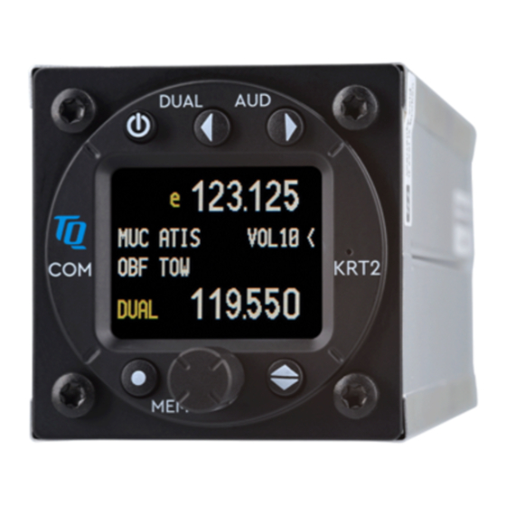
Doc.-Nr: User & Installation manual DE-3000-800100e VHF- Communication Transceiver Revision 12.2 KRT2 Jan. 2016 2.2 Display Indication Meaning Remarks RX is displayed during Reception reception (squelch opened) Transmitter operates Transmission normally Transmitter was turned off automatically after 2 min continuous operation 119.700... -
Page 13: Audio Menu Levels
Doc.-Nr: User & Installation manual DE-3000-800100e VHF- Communication Transceiver Revision 12.2 KRT2 Jan. 2016 A-match Antenna error Bad antenna match a = AUX. Input active v = VOX active Status of certain Audio a v e menu functions e = external Intercom... -
Page 14: Self-Test Error Reports
Doc.-Nr: User & Installation manual DE-3000-800100e VHF- Communication Transceiver Revision 12.2 KRT2 Jan. 2016 2.4 Self-test error reports Display Meaning Remark Return the transceiver for Er_PLL Internal error, no maintenance transmission Return the transceiver for Er_ADC Internal error, maintenance Return the transceiver for Er_FPA Internal error;... -
Page 15: Operation
Doc.-Nr: User & Installation manual DE-3000-800100e VHF- Communication Transceiver Revision 12.2 KRT2 Jan. 2016 3 OPERATION 3.1 General In the normal operating mode in which the turning knob always is connected to the volume (VOL). The normal operating mode can be left by pressing the AUD, FREQ or MEMORY button. -
Page 16: Frequency Selection
Doc.-Nr: User & Installation manual DE-3000-800100e VHF- Communication Transceiver Revision 12.2 KRT2 Jan. 2016 3.3 Frequency Selection There are two different frequency selection methods: • Direct Input • Selection from the favourite list (index 0-99) 3.3.1 Direct Frequency Selection The Standby-Frequency is set with the turning knob in 3 different ranges. -
Page 17: Frequency Selection From The Favorites List
Doc.-Nr: User & Installation manual DE-3000-800100e VHF- Communication Transceiver Revision 12.2 KRT2 Jan. 2016 3.3.2 Frequency Selection from the Favorites List By pressing MEM and operating the turning knob a specific favourite list position can be accessed [xx] (xx = index 0 … 99). When frequency and station identifier have been defined, they will be displayed in the Standby and station identifier windows. - Page 18 Doc.-Nr: User & Installation manual DE-3000-800100e VHF- Communication Transceiver Revision 12.2 KRT2 Jan. 2016 In the identifier window a blinking cursor will show up under extreme left character. The turning knob selects the desired character. The AUD button positions the curser one character to the right.
- Page 19 Doc.-Nr: User & Installation manual DE-3000-800100e VHF- Communication Transceiver Revision 12.2 KRT2 Jan. 2016 SORT? will show up which stays for 20 seconds and it will be activated with or skipped with MEMORY. When activated all 99 favorites will sorted in alphabetical order and the process can take several minutes.
-
Page 20: Aud - Audio Menu
Doc.-Nr: User & Installation manual DE-3000-800100e VHF- Communication Transceiver Revision 12.2 KRT2 Jan. 2016 3.4 AUD – Audio Menu Any action in the Audio Menu requires the pointer (<) to be next to the Audio menu window (see picture). When the pointer is next to... -
Page 21: Vox - Intercom Voice Trigger Level Setting
User & Installation manual DE-3000-800100e VHF- Communication Transceiver Revision 12.2 KRT2 Jan. 2016 The Squelch setting is depending on several factors. For engine driven airplanes an initial setting of 03-05 is recommended. For gliders a setting of 2 is recommended. The lower the Squelch level value the higher is the input sensitivity. -
Page 22: Txm - Ptt Switch Selection
Doc.-Nr: User & Installation manual DE-3000-800100e VHF- Communication Transceiver Revision 12.2 KRT2 Jan. 2016 For use in gliders the VOX has to be set to 10 for disabling the speaker control. 3.4.5 TXm – PTT Switch Selection Pressing the AUD button three times enables the turning knob to enable certain PTT switches. -
Page 23: Dim - Display Brightness
Doc.-Nr: User & Installation manual DE-3000-800100e VHF- Communication Transceiver Revision 12.2 KRT2 Jan. 2016 3.4.8 DIM – Display Brightness Pressing the AUD button six times enables the turning knob to set the display brightness. Display lighting current drain at maximum brightness is 40mA. -
Page 24: Sit - Side Tone
Doc.-Nr: User & Installation manual DE-3000-800100e VHF- Communication Transceiver Revision 12.2 KRT2 Jan. 2016 3.4.10 SIT – Side tone Pressing the AUD button eight times enables the turning knob to set the side tone volume. (for gliders should be set to 01) SITnn Range: 0 –... - Page 25 User & Installation manual DE-3000-800100e VHF- Communication Transceiver Revision 12.2 KRT2 Jan. 2016 individually. The microphone signal level is dynamically displayed as bar and as numeric value (from-0.00-to-1.00) in the line below. The initial MIC-level should be 05, the engine should be running, use a headset or earphone and speak at a normal voice level to fine-tune the MIC-level.
- Page 26 Doc.-Nr: User & Installation manual DE-3000-800100e VHF- Communication Transceiver Revision 12.2 KRT2 Jan. 2016 The display of microphone type (lower right side) is done upon activation of the microphone menu. When an Electret microphone is recognized, internal switchover to the Electret microphone type will take place.
-
Page 27: Menu Lock
Available Locked and not available 3.5 DUAL Watch Because the communication transceiver KRT2 contains only one receiver, DUAL watch is achieved by alternating between the Active and Standby frequencies. The DUAL button activates and deactivates the dual watch function. - Page 28 User & Installation manual DE-3000-800100e VHF- Communication Transceiver Revision 12.2 KRT2 Jan. 2016 When DUAL watch is activated, “DUAL“ is displayed on the lowest line. The pointer next to the DUAL display indicates the frequency on which there is reception.
-
Page 29: Transmitter Operation
Doc.-Nr: User & Installation manual DE-3000-800100e VHF- Communication Transceiver Revision 12.2 KRT2 Jan. 2016 3.6 Transmitter Operation The unit transmits on the active frequency (upper line) as long as a PTT (press to talk) switch is pressed. Transmission Reception „TX“ indicates normal transmitter operation. -
Page 30: Speciality Of Two Ptt
User & Installation manual DE-3000-800100e VHF- Communication Transceiver Revision 12.2 KRT2 Jan. 2016 In case there is just one PTT button available and multiple headsets in use both the PTT-L and PTT-R should be tired together, see also “3.4.5 TXm –... -
Page 31: Optical Side Tone
User & Installation manual DE-3000-800100e VHF- Communication Transceiver Revision 12.2 KRT2 Jan. 2016 3.6.3 Optical side tone Especially when used in gliders, where headsets are generally not worn and thus no side tone is heard, it is very helpful to see if the microphone is working. -
Page 32: Resetting To Factory Settings
User & Installation manual DE-3000-800100e VHF- Communication Transceiver Revision 12.2 KRT2 Jan. 2016 3.7 Resetting to factory settings Returning to the factory settings can only be initiated during power-up. To do this, during power-up the MEMORY and DUAL buttons must be pressed simultaneously and the display will show “SET DEFAULTS”. -
Page 33: Erase - Erasing The Favorites List
3.8.2 Channel Spacing When in the SET UP – Menu pressing the FREQ (S) button will change the KRT2 into the Channel Space submenu. The desired channel spacing then can be selected and the (X) then indicates the actual channel spacing. -
Page 34: Remote Control
Data transmission between the transceiver KRT2 and the remote control unit (KRT2-RC) is checked once every minute. A “r” in the upper right corner is displayed when there is no malfunction. The KRT2-RC can also operate the KRT2 in a fully stand-alone mode such the KRT2 can be installed anywhere in the aircraft and be operated remotely by the KRT2C. -
Page 35: Installation
Jan. 2016 5 Installation 5.1 Limitations The KRT2 is designed as a single block unit for the installation in cockpit environment of general aviation aircrafts under consideration of the following limitations: Installations are to be made in accordance with appropriate EASA or FAA approved guidelines. -
Page 36: Installation Hints
Emission Identifier: 5k00A3E for 8,33kHz channel spacing 5.4 Scope of delivery Part Number Description KRT2 KRT2 - VHF Transceiver ZUB2 (4 pcs) Mounting screw KRT2 - for panels up to Operation and Installation Manual EASA Form 1 36 / 61... -
Page 37: Unpacking And Inspecting The Equipment
Doc.-Nr: User & Installation manual DE-3000-800100e VHF- Communication Transceiver Revision 12.2 KRT2 Jan. 2016 5.5 Unpacking and Inspecting the Equipment Carefully unpack the equipment. Damages due to transportation must immediately be reported to the shipping company. Save the shipping container and all packing material to substantiate your claim. -
Page 38: Electrical Connections
Doc.-Nr: User & Installation manual DE-3000-800100e VHF- Communication Transceiver Revision 12.2 KRT2 Jan. 2016 5.7 Electrical Connections The 15-pin D-Sub connector contains all electrical connections except the antenna. The battery plus connection must be protected with at least 3-amps slow blow fuse! -
Page 39: Speaker & Open Microphone
Revision 12.2 KRT2 Jan. 2016 When the AUTO mode is selected in the MIC-Setup menu the KRT2 automatically recognizes on MIC-L (pin 3) which microphone type has been switched and acts accordingly. Both inputs must not be wired together. L is the master. -
Page 40: Earphone Connection
Doc.-Nr: User & Installation manual DE-3000-800100e VHF- Communication Transceiver Revision 12.2 KRT2 Jan. 2016 intercom switch (indicating “e”), other vice a feedback from the speaker will occur. 5.7.3 Earphone Connection Several earphones of same type can be connected in parallel. The total impedance should not be less than 60 Ohms. -
Page 41: Final Audio-Setup
Doc.-Nr: User & Installation manual DE-3000-800100e VHF- Communication Transceiver Revision 12.2 KRT2 Jan. 2016 5.8 Final Audio-Setup This is an overview for a correct audio set up depending on the usage. Ground the unused MIC.-R input if unused. 5.8.1 For gliders Press button AUD 3x for VOX: Set to VOX 10 (turn off) or open the intercom switch (indicating “e”). -
Page 42: Wiring
Doc.-Nr: User & Installation manual DE-3000-800100e VHF- Communication Transceiver Revision 12.2 KRT2 Jan. 2016 5.9 Wiring 5.9.1 Wire Gauges Supply lines (Power, GND): AWG18 (0,83 mm²) Control lines: AWG22 (0,38 mm²) All wires must be aviation certified. 5.9.2 Connector Pin-Configuration If manual intercom is not used, pin 12 should be grounded. - Page 43 Doc.-Nr: User & Installation manual DE-3000-800100e VHF- Communication Transceiver Revision 12.2 KRT2 Jan. 2016 Microphone-Setup: set L / R as required for headset, leave not in AUTO 43 / 61...
-
Page 44: Glider Two Place Connection
Doc.-Nr: User & Installation manual DE-3000-800100e VHF- Communication Transceiver Revision 12.2 KRT2 Jan. 2016 5.9.3.2 Glider two place connection Microphone-Setup: leave in L =11, (not AUTO) 44 / 61... -
Page 45: Glider Single
Doc.-Nr: User & Installation manual DE-3000-800100e VHF- Communication Transceiver Revision 12.2 KRT2 Jan. 2016 5.9.3.3 Glider single Microphone-Setup: leave with L =11 for dynamic, (not AUTO) 45 / 61... -
Page 46: Motor Glider Single
Doc.-Nr: User & Installation manual DE-3000-800100e VHF- Communication Transceiver Revision 12.2 KRT2 Jan. 2016 5.9.3.4 Motor glider single Microphone-Setup: set L / R as required for headset, leave not in AUTO-mode. 46 / 61... -
Page 47: Motor Glider Dual
Doc.-Nr: User & Installation manual DE-3000-800100e VHF- Communication Transceiver Revision 12.2 KRT2 Jan. 2016 5.9.3.5 Motor glider dual Dynamic Mikrophon Microphone-Setup: R for headsets, leave menu in AUTO mode. 47 / 61... - Page 48 Doc.-Nr: User & Installation manual DE-3000-800100e VHF- Communication Transceiver Revision 12.2 KRT2 Jan. 2016 Electret Mikrophon Microphone-Setup: leave L = 3..9 (in case of dynamic =11), R=3 (not AUTO-mode). 48 / 61...
-
Page 49: Wiring For Dynamic Microphones
User & Installation manual DE-3000-800100e VHF- Communication Transceiver Revision 12.2 KRT2 Jan. 2016 5.9.4 Wiring for dynamic microphones Special attention is required for the wiring for dynamic microphones. Because of the required high gain any mistake on the ground wiring leads to interferences and feed backs. -
Page 50: Antenna
Doc.-Nr: User & Installation manual DE-3000-800100e VHF- Communication Transceiver Revision 12.2 KRT2 Jan. 2016 5.10 Antenna 5.10.1 Antenna Selection A 50 Ohms impedance VHF-COM-antenna is required. The antenna must be approved in respect to aircraft type and installation location. -
Page 51: Microphone General
Communication with the VOX system requires pin 12 to be connected to GND by means of one or two intercom switches. The KRT2 unit transmits only when a PTT switch is pressed. Cockpit noise suppression is only possible with differential microphones used in modern headsets. -
Page 52: Post-Installation Check
Doc.-Nr: User & Installation manual DE-3000-800100e VHF- Communication Transceiver Revision 12.2 KRT2 Jan. 2016 5.12 Post-Installation Check A certified maintenance shop must verify the proper operation of the VHF transceiver or as required by national regulations. A complete check of all airplane systems is required to certify that the new wiring is not causing any malfunction. -
Page 53: Starting Up
Doc.-Nr: User & Installation manual DE-3000-800100e VHF- Communication Transceiver Revision 12.2 KRT2 Jan. 2016 5.13 Starting Up Switch the unit on with the ON button. The following display will appear: The start display shows device type and the software number. It then changes into the normal operating mode (Direct Input). -
Page 54: Drawings
Doc.-Nr: User & Installation manual DE-3000-800100e VHF- Communication Transceiver Revision 12.2 KRT2 Jan. 2016 5.15 Drawings Dimensions 5.15.1 54 / 61... -
Page 55: Installation Directions
Doc.-Nr: User & Installation manual DE-3000-800100e VHF- Communication Transceiver Revision 12.2 KRT2 Jan. 2016 5.15.2 Installation Directions Panel Cut-out 55 / 61... -
Page 56: Maintenance
Doc.-Nr: User & Installation manual DE-3000-800100e VHF- Communication Transceiver Revision 12.2 KRT2 Jan. 2016 6 Maintenance 6.1 Periodic Maintenance No scheduled servicing tasks are required on the KRT-2 VHF unit. 6.2 Repair Only exchange and flat repair of the equipment is permitted. In case of equipment failure, the unit must be sent to the manufacturer. -
Page 57: Annex
Doc.-Nr: User & Installation manual DE-3000-800100e VHF- Communication Transceiver Revision 12.2 KRT2 Jan. 2016 7 ANNEX 7.1 Frequency / Channel- schedule The following table contains the operating and displayed frequencies between 118.000 and... 118.100 MHz. The table can be continued up to 136.975 MHz following the same principle. -
Page 58: Technical Data
Doc.-Nr: User & Installation manual DE-3000-800100e VHF- Communication Transceiver Revision 12.2 KRT2 Jan. 2016 7.2 Technical Data GENERAL Compliance ED-23C Class 4-6 Standards RTCA DO-186B Class 4 ED-23C Class C-D-E-H1/2 RTCA DO-186B Class H1/2 RTCA DO-178B/ED-12B Level D ETSO-2C169a Standards... - Page 59 Doc.-Nr: User & Installation manual DE-3000-800100e VHF- Communication Transceiver Revision 12.2 KRT2 Jan. 2016 Power Supply 9 VDC to 33VDC test @ 13.8VDC Transmitter: 2.0 A (typ.) Receiver: 0.13 A Illumination 0.01A to 0.07A Audio Power amp. Up to 1A...
- Page 60 Doc.-Nr: User & Installation manual DE-3000-800100e VHF- Communication Transceiver Revision 12.2 KRT2 Jan. 2016 TRANSMITTER POWER OUTPUT 6 W (nominal) @ >13.5V 4 W (minimal) HARMONIC DISTORTION <10 % at 70 % modulation SIDETONE OUTPUT >0,5W an 300Ω (head set output) MICROPHONE INPUTS 2 x standard (50mV…2V) into 100Ω...
- Page 61 Doc.-Nr: User & Installation manual DE-3000-800100e VHF- Communication Transceiver Revision 12.2 KRT2 Jan. 2016 61 / 61...