Table of Contents
Advertisement
Advertisement
Table of Contents

Related Manuals for Centurion SMARTGUARD


Summary of Contents for Centurion SMARTGUARD
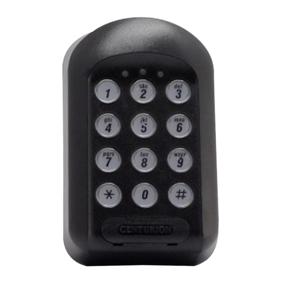
- Page 1 SMARTGUARD pocket installation guide HIGH SECURITY KEYLESS ACCESS CONTROL...
- Page 2 2. How to use this Guide The procedures in this Guide require the user to perform certain sequential actions on the SMARTGUARD keypad. To assist you, the combined state of the three LED indicators on the keypad correspond with particular steps within a procedure. When carrying out the...
- Page 3 5. Technical specifications Supply voltage 12V - 24V AC/DC Standby current 32mA 180mA1 Maximum current Operating temperature -15C to +55C Operating humidity 0-90%2 1 x 3A @ 50V3 Output relay rating Open collector rating 2 x 50mA @ 24V Housing material Polycarbonate Degree of protection IP55...
- Page 4 Indicator LEDs Enter the following keystrokes: 1. Enter Program Mode 2. Select Add Menu 3. Enter user address 4. Enter access code 5. Select channel 6. Assign channel 7. Enter access limit 8. Exit Add Menu 9. Exit Program Mode Example: Add access code into address...
- Page 5 10. Setting the anti-hack parameters The following procedure sets the number of wrong access codes that the SMARTGUARD will accept before becoming inactive, as well as the time for which it will remain inactive. The factory default for wrong access codes is three, while the default reset time is 60 seconds.
- Page 6 11. Setting the key wipeout time The following procedure sets the number of seconds for which keystrokes remain valid. This ensures that if a partial code has been entered, it is wiped out of the keypad buffer after a preset time, and must be re-entered in its entirety.
- Page 7 Memory Module, and keep it in a safe place. Restoring from a Backup Memory Module will overwrite any information that was previously contained in the SMARTGUARD unit 15. Defaulting the unit Both the Master Code and the system parameters (timers, alarm functions, etc.) can be reset to Factory Defaults.
- Page 8 Attach the rear pane to the mounting surface, Anti-knock Shield or gooseneck with the mounting screws supplied as shown below. M4 washers and nuts SMARTGUARD Anti-knock Shield Mounting screws SMARTGUARDair backing plate Mounting...
- Page 9 (Channel 3) To third party alarm system 18. Typical connection diagram If your supply voltage to the SMARTGUARD exceeds 24V AC or 30V DC, fit the supplied 150R resistor in series with the supply wire as shown. From external 12V - 24V DC/AC...
- Page 10 Email address: Physical address: For your convenience you will find an Address Register included in your SMARTGUARD packaging. Use this Address Register to record which addresses have been assigned, their access code and which channel will be activated by that address.
- Page 11 YouTube.com/CenturionSystems @askCentSys Subscribe to the newsletter: www.CentSys.com/Subscribe Sharecall 0860-CENTURION (0860 236 887) Head Office: +27 11 699 2400 Sharecall Technical Support 0861 003 123 or +27 11 699 2481 from 07h00 to 18h00 (GMT+2) Sharecall numbers applicable when dialed from within South Africa only) 0.07.A.0158_10102014...
Need help?
Do you have a question about the SMARTGUARD and is the answer not in the manual?
Questions and answers