
Related Manuals for DCT Syrus


Summary of Contents for DCT Syrus
- Page 1 Syrus Installation and Configuration Manual V1 - December 2013 D i g i t a l C o m m u n i c a t i o n T e c h n o l o g i e s...
-
Page 2: Table Of Contents
DETAILED COMMAND EXPLANATION ..................... 22 UNIT'S ID ................................. 22 IMEI AS ID ............................... 22 ENABLING THE UNIT ON GSM AND GPRS ....................23 DESTINATIONS (DPS AND DAS) ........................ 25 SYRUS COMMANDS ............................27 DA - D ..............................27 ESTINATION DDRESS Qualifiers: Q, S, R. - Page 3 Qualifiers: R..................................... 29 Example: ....................................29 Extended EV Tags formats: .............................. 30 Example: ....................................30 GC - C ............................ 31 OUNTERS IMERS ISTANCERS Qualifiers: Q, S, R................................... 31 Examples:....................................32 GS - S ................................... 33 PEED IMIT Qualifiers: Q, S, R................................... 33 Examples:....................................
-
Page 4: Introduction
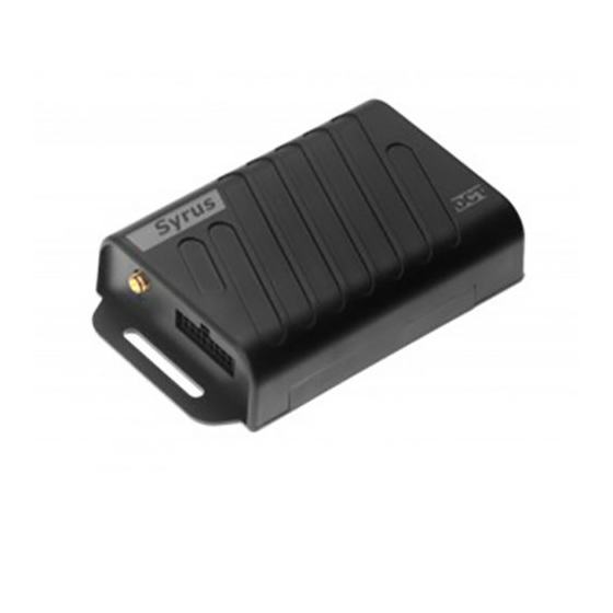
Introduction This manual is intended for Syrus firmware 2 only The following is an introduction manual for the DCT Syrus GPS tracking device, its main purpose is to provide a quick reference for the installation and configuration of the device. -
Page 5: Specifications
Specifications Power DC Voltage: 8V - 32 V Current consumption: With Internal battery at null charge (IDLE) Long term average: 50 mA @ 12V. Long term average while on power saving mode: 6mA @ 12V. Reverse voltage polarity protection. ... - Page 6 GPS Module GPS Solution MTK MT3329 Frequency L1, 1575.42MHz Sensitivity Acquisition -148dBm, cold start Reacquisition -160dBm Tracking -165dBm Channels TTFF Hot start: 1 second typical Warm start: 33 seconds typical Cold start: 35 seconds typical Altitude Maximum 18,000m (60,000 feet) Velocity Maximum 515m/s (1000 knots) Acceleration...
-
Page 7: Leds
LED is OFF, it will also flash once when the unit has successfully restarted and initialized the Syrus application. To verify if the unit is ON, check the state of the GPS and NET LEDs, which will always show some kind of activity. -
Page 8: Inputs And Outputs
Inputs and Outputs rev1 – Dec 2013 www.digitalcomtech.com... -
Page 9: Care And Caution
Care and Caution Operating Temperature Due to the limitations on the operation of the Lithium polymer battery, the temperature while charging the battery must be 0ºC to 45ºC, and the regular operating temperature must be -20ºC to 70ºC. For more information about the Lithium polymer batteries, visit: http://en.wikipedia.org/wiki/Lithium-ion_polymer_battery orhttp://www.batteryuniversity.com/parttwo-34.htm How to remove SIM Card... -
Page 10: Installation
Faraday cage, which could lower the signal strength. The Syrus has an internal GPS antenna, and a connector for an optional external GPS antenna. When using the internal antenna, the units must be located so that it has minimal metal obstructions to the sky view and with the upper part facing up. - Page 11 If the switch disconnects the positive voltage of the vehicle's battery, the Syrus can be connected before or after the switch. When connected before it will keep on receiving the vehicle's power whenever the switch is off. If it is connected after the switch, the unit will run with its optional back up battery whenever the switch is turned off.
-
Page 12: Getting Started
Setting the unit's ID The default Syrus behavior is to use the unit's IMEI as ID. It is recommended to use this setting as the IMEI is unique for each unit. However it is possible to use a user defined ID in order for the unit to be identified on the AVL server. -
Page 13: Creating A Destination Point (Dp)
At this point the unit will try to register on GSM and on GPRS (you can see this status live on SyrusDesk). Although PIN and APN parameters take effect immediately the unit may take up some time on registering to the network if previous erroneous information was used. You can wait for the unit to register or you can speed up the process by resetting the communications module with the>SXAGP1<... -
Page 14: Creating A Destination Address (Da)
The server is accepting the connection but it is closing it immediately, or a few seconds later. The Syrus is behind a cellular carrier's NAT which has the selected port blocked. The selected APN has no Internet access. Or in case of a private network, the APN has no access to the network where the AVL server is running. -
Page 15: Tying A Signal To An Event
it triggers a TD signal on a time-only basis set by the Minimum Time Between Reports parameter. Please refer to the message for more information. Let's use a reporting period of 5 minutes (300 seconds). For no special reason let's choose TD signal 8 to do the job: >STD80300<... - Page 16 Examples: Periodic report: To define event 05 to send an EV Event Message every 3 minutes, use the TD message to configure a Time & Distance signal to trigger every 3 minutes: >STD70180< Define the event with signal TD7 as trigger: >SED05NV0;TD7+<...
- Page 17 TCP listener applications that will show you the RAW data received, and confirm that the reports from Syrus are being received properly by the server. Another useful tool is a network sniffer that allows you to analyze the traffic on a given TCP/UDP connection while the the AVL server is running.
- Page 18 #Event triggered by T&D signal >SED37NV4;TD8+< #Input report event >SED05NV4;IP3+< #end You can copy and paste this script to a new empty text file and have it save with a .tmf extension and load it with Syrus Desk. rev1 – Dec 2013 www.digitalcomtech.com...
-
Page 19: Event Machine
Event Machine The unit's reporting is controlled by an Event Machine which constantly evaluates user defined events. These events allow the user to create a reporting schema and functionality controlled by triggers and actions. Events can be consulted or configured at any time with the ED message throughout the Command Console, enabling the user to alter the Event Machine parameters at any time locally or over the air. -
Page 20: Actions
Once you have defined a trigger (and/or a set of triggers) the next step for configuring the Syrus TM event machine, is to tell the unit what to do when a trigger goes off. There are two types of actions the unit may take when a trigger goes off. These are the report action and the user-defined action. -
Page 21: Signals
Signals As described in the previous section, the event machine takes actions like reporting or switching outputs whenever a user defined trigger goes off. This trigger is configured by the user with the logical combination of situations. Situations make reference to a vehicle state which is in fact represented by signals and their state. -
Page 22: Detailed Command Explanation
Syrus Commands: XAID Syrus is configured by default to use its International Mobile Equipment Identity (IMEI) as ID instead of a user-set value. This is useful for managing units without having to worry about duplicated or changed IDs. It also eases the programming task as this number is already stored on every unit. -
Page 23: Enabling The Unit On Gsm And Gprs
NET (green) LED. When the unit is GSM-registered it is able to make or receive telephone calls and 2-way SMS communication. Warning: The PIN may be changed over the air which will cause the Syrus to loose communications with the server. rev1 – Dec 2013... - Page 24 GPRS network as soon as the GSM registration process is done and the APN parameter is set. The Syrus will not start a GPRS session if it is not registered on the GSM network. And when the GSM network is lost the GPRS session is lost too. However the unit may work on the GSM network regardless of the GPRS session state.
-
Page 25: Destinations (Dps And Das)
SMSs or make voice calls. They are also used as authorization numbers for replying to receive SMSs commands and/or answering incoming voice calls. Defining if a report should be sent as a Syrus command or using a custom user message is also done here. - Page 26 Destination Addresses (DAs) A Destination Address is a user-defined group of Destination Points. This enables some reporting commands to route their report to several destinations at the same time with a single definition. Up to 10 (0 to 9) DAs may be defined. Refer to the message for more information.
-
Page 27: Syrus Commands
Syrus commands DA - Destination Address Qualifiers: Q, S, R. A Destination Address is an association of Destination Points. These allows an event defined with the ED message to be routed to multiple receivers at the same time by selecting the Destination Address (or group) that holds all of the desired destinations (IP-types, Telephones, Serial Port). -
Page 28: Ed - Event Definition
Qualifiers: Q, S, R. This message is used to define events. These events define the Event Machine configuration for the Syrus . An event is created by defining a boolean combination of signals as a trigger, a routing indication for a generated event message and a possible Configuration Command to be executed when the event occurs. -
Page 29: Ev - Event Message
EV - Event Message Qualifiers: R. This message is generated when an event is triggered and reported. The message has the following format: AABBBBCDDDDDEEEFFFFFGGGGHHHHHIIIJJJKL[EXTENDED- EV TAGS] AA: Event index. Range 0-99. BBBB: Number of weeks since 00:00 AM January 6, 1980. C: Day of week. -
Page 30: Extended Ev Tags Formats
Extended EV Tags formats: ;AC=AAA... AAA...: Instant acceleration measured in Miles per hour per seconds ;AL=AAA... AAA...: Altitude is A meters Above Mean Sea Level (AMSL). This value will be -9999 when no valid GPS data is available. ;BL=AAA... -
Page 31: Gc - Counters, Timers, Distancers
GC - Counters, Timers, Distancers Qualifiers: Q, S, R. This message is used to configure and manipulate internal counters. Each counter can be configured as a user-controlled counter, a timer, or a distancer (counter updated by the traveled distance). Please refer to the Quick Command Reference section for a few examples about counter use. -
Page 32: Examples
Examples: Continuous counter: Set counter 03 on Timer mode. When the counter's value reaches 5 minutes the C03 signal should transition to true. The counter shall not recycle its value when reaching the 5 minutes or else we will end up with a periodic C03 signal: To do this we define a timer with threshold value set to 300 seconds with no delta value: >SGC03TC00300<... -
Page 33: Gs - Speed Limit
GS - Speed Limit Qualifiers: Q, S, R. This message is used to configure the speed limits that can be used to trigger events. The message has the following format: AABCCCC AA: Index. Range 00-09. Specifies one of the speed limits associated with a speed limit signal SAA. -
Page 34: Id - Identification
ID - Identification Qualifiers: Q, S, R. This message is used to set/query unit's ID. When changing the ID it is necessary to reset the unit using the command in order to reestablish the current connections to any Destination Point using the new ID. The message has the following format: A[AAA...] A[AAA...]: Identification code assigned to the vehicle. -
Page 35: Pv - Position-Velocity
PV - Position-velocity Qualifiers: Q, R. This message gives the unit's current position, velocity, heading, source of information and age of the data. The message has the following format: AAAAABBBCCCCCDDDDEEEEEFFFGGGHI AAAAA: Time of day. Time of the generated report. This number represent the seconds elapsed since 00:00 of the current day. -
Page 36: Rf - Radio Frequency Module Configuration
RF - Radio Frequency Module Configuration Qualifiers: Q, S, R. This message is used to configure Cellular Network parameters. Any RF parameter can be left empty by issuing the command without the B string. The message has the following format A[BBB...] A: RF parameter to be configured. -
Page 37: Rt - Reset Message
RT - Reset message Qualifiers: S, R. When used with qualifiers it serves multiple initializations purposes. The valid options are: Without a Qualifier (i.e: >SRT<): Restarts the unit. This option does not delete any configuration parameter or stored information. ;CONFIG: Resets almost all the configuration of the unit. The preserved parameters are: PIN, APN, ID, Destination Points, IMEI as ID. -
Page 38: Si - Sim Card Id
This message allows to consult the SIM Card ID of the SIM card currently installed on the Syrus. Examples: To consult the SIM card ID, send: >QSI< The Syrus will reply like this: >RSI8957123310512805597< If no SIM card is installed, the response will be error 13: >RER13;QSI< rev1 – Dec 2013... -
Page 39: Ss - Signal Status
SS - Signal Status Qualifiers: Q, S, R. This message allows for the inspection of signals' state and the setting of outputs and other user controllable signals. Please refer to the Signal List section, for a list of valid signals. The message has the following format: AAA[B] AAA: Index. -
Page 40: St - Status
ST - Status Qualifiers: Q, R. This message provides information about the unit's GPS receiver. The message has the following format when using no modifier (>QST<): AABCDDEFGGH AA: GPS satellite signal acquisition and tracking status. 00: Doing position fixes. 01: Don't have GPS time yet. -
Page 41: Td - Time And Distance
TD - Time and Distance Qualifiers: Q, S, R. The Time and Distance signals are set by its corresponding Time and Distance counter which is a counter that follows a Time and Distance criteria. This criterion allows creating a counter that does not follow a time or distance criteria independently from each other, instead, combines these two variables to generate an intelligent trigger to be used for a more efficient vehicle tracking. -
Page 42: Vr - Version Number
Time parameter and setting the others to zero. To define a time only criteria of 15 minutes (900 seconds): >STD60900000000000000< >STD60900< VR - Version Number Qualifiers: Q, R. This message returns the unit's firmware version. For example: Firmware 2.1.18: >RVR; Syrus 2.1.18;ID=356612024116677< rev1 – Dec 2013 www.digitalcomtech.com... -
Page 43: Xadp - Destination Points
DP 05 must always be different to the port defined for DP 04. DP 04 can only be deleted once DP 05 has been deleted first. After configured the DP 05 it is necessary to restart the Syrus using the>SRT< command. For IP-type destinations, i.e. Destination Points 00 to 05 use the following format: AABCD[DDD...];E[EEE...]... -
Page 44: Examples
For Telephone destination, i.e. Destination Points 10 to 14 use the following format: AABCD[DDD...] AA: Index for Telephone destinations. Range 10-14. B: DP type/Action: U: Delete the Destination Point 0: Report messages are sent as Configuration Commands responses to this ... -
Page 45: Xaef - Extended-Ev Message Formats
XAEF - Extended-EV message Formats Qualifiers: Q, S, R. This message allows the creation and configuration of up to three sets of information tags to be used by an event having the Message ID qualifier set to A, B or C. The message has the following format: A[BBB...] A: Identifier of the extended-EV format being set or consulted. -
Page 46: Xaid - Imei As Id
XAID - IMEI as ID Qualifiers: Q, S, R. This message tells the unit whether to use or not its IMEI as ID. When changing this parameter, it is necessary to reset the unit using the command in order to reestablish the current connections to any Destination Point using the ID setting. -
Page 47: Xans - Network Status
XANS - Network Status Qualifiers: Q, R. Use this message to consult the state of the GPRS session and the state of the TCP sockets of every IP-type Destination Point. The response message information is presented in groups separated by a ";" character and each group separates its data with a ","... - Page 48 GSM RSSI 0 = -113 dBm or less 1= -111 dBm 2 to 30 = -109 to -53 dBm 31 = -51 dBm or greater 99 = not known or not detectable GPRS attached state ...
- Page 49 An example of the response for this message could be: >RXANS1,intnet.cxn,,,;1,1,null,5,31,1,5,10.1.17.207,1;socket://visionairegps.com:8040,3,1024,66.228.127.212,804 0,3,,\;,,,;3,1,1,0,4;< Which indicates that the Air Interface is up, the APN set is internet.cxn, and the PIN is empty; The SIM is inserted, and ready, registered to GSM and roaming, the RSSI is 31, registered to GPRS and roaming, and the local address is 10.1.17.207;...
-
Page 50: Error List
Error List 00 - Unrecognized command. 01 - Internal error. Please verify the syntax of the Configuration Command and try again. 02 - The message is not delimited by > and/or < 03 - ID miss match on incoming post fix ";ID=" ... -
Page 51: Signal List
F17: Collision. when a collision is detected. G05: Idle signal. True when Syrus determines that the vehicle is in idle state. This happens when the vehicle's engine is turned on but the vehicle is not moving. G06: GPS antenna connection status signal. True when the GPS antenna is connected. -
Page 52: Script Example
Script example #- Syrus 2 Script - Standard Configuration #- v1 - last edit DEC 2013 #- Extended formats >SXAEFA;VO< #- Heading Definition = 45 Degrees >SXAGH001045< #Event 00 - Periodic Position Report >SED00NA0;J00C02|C03|F00&+;XCT=SGC03DR00800;XCT=SGC02TR00120< #- Idle Condition Event #- Speed Limit Definition = 6 mph [10kph] - Signal S01 >SGS0110060<... - Page 53 #Event 05 - Slow Traffic >SED05NA0;C08+< #Power Events #Event 06 - Power Disconnection >SED06NV0;F13-< #Event 07 - Power Re-connection >SED07NV0;F13+< #Event 08 - Periodic report with Ignition Off >SED08NV0;C01+< #- Inputs Detection Events #Event 09 - Input 1 Activated >SED09NV0;IP1+< #Event 10 - Input 2 Activated >SED10NV0;IP2+<...
Need help?
Do you have a question about the Syrus and is the answer not in the manual?
Questions and answers