
Related Manuals for Zonerich AB-58C


Summary of Contents for Zonerich AB-58C
-
Page 1: Maintenance Manual
Zonerich AB-58C Maintenance Manual Zonerich Business Machine Co., Ltd http://www.zonerich.com... -
Page 2: Table Of Contents
Contents Ⅰ .Product Appearance and Configuration:........1 Ⅱ.Common Problems and Troubleshooting........5 Ⅲ.DIP Switch Function..............7 Ⅳ.Replace mainboard............... 9 Ⅴ.Replace the print head..............11 Ⅵ. Part of schematic circuit diagram..........13... -
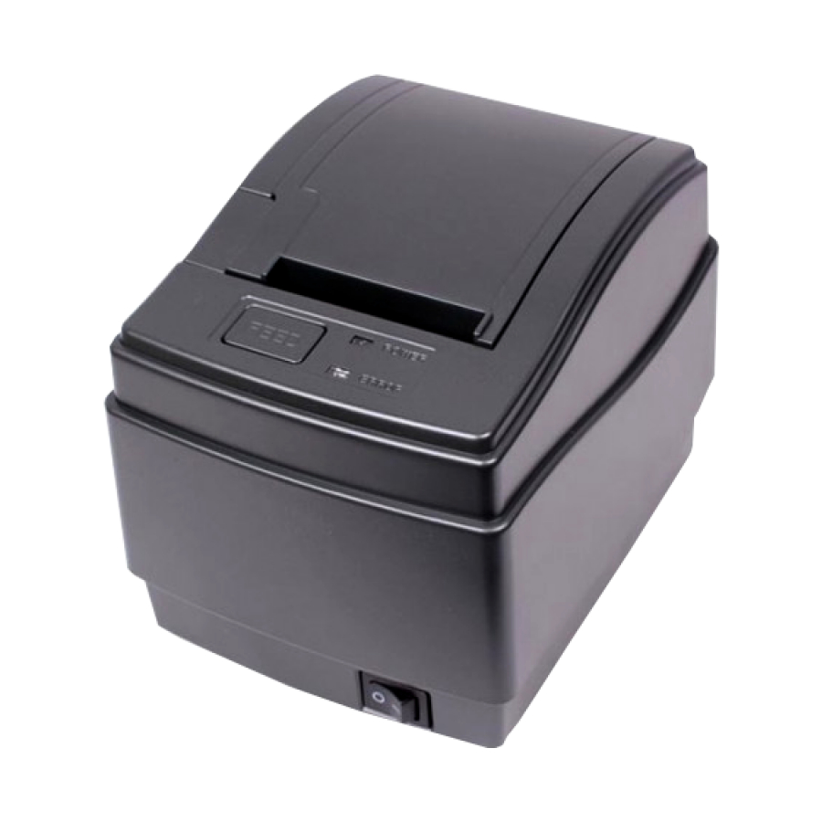
Page 3: Ⅰ.product Appearance And Configuration
Ⅰ.Product Appearance and Configuration : Product appearance Front Back Bottom Printer parts and conventional fault diagnosis 1. Print Head: The print head is one of the most important parts of the printer, mainly including the thermal element and electric motor. The thermal element prints out the text and graphics and the motor is used to move the paper. - Page 4 Print head has a certain life span, which is related to the working environment and the quality of paper. The bad environment such as dusty environment and the poor quality of paper will reduce the service life of the print head. After a period of time of use, the print head requires the cleaning and maintenance.
-
Page 5: Product Parts
5. Communication interface: It is used to achieve the data exchange between the printer and the PC, the communication interface board is removable and multiple interfaces such as serial interface, parallel interface, USB interface and Ethernet interface can all be supported. When the printer does not print or print out messy codes, you can replace with a better communication interface board to judge whether it is the failure caused by the communication interface board. -
Page 6: Ⅱ.common Problems And Troubleshooting
Ⅱ.Common Problems and Troubleshooting Common Problems Solutions 1. Messy codes with Check whether the host PC and the printer have the same serial interface baud rate Entirely unclear: poor quality of thermal paper; change the printing density from the thin mode to the tick mode. 2.Unclear printing effect Partly unclear: the print head is dirty. -
Page 7: Ⅲ.dip Switch Function
Ⅲ.DIP Switch Function The DIP locates at the bottom of the printer. Open the DIP cover and the DIP is shown as in the figure. The user needs to adjust DIP to ON / OFF according to the actual needs. DIP switch self-test page’s DIP default setting Parallel... - Page 8 Printing Printing DIP3 DIP4 DIP7 DIP8 Buzzer Byte mode density mode Turned Thin Double byte (defaul (default) characters (default) Epson Turned Thick mode Single byte (default)...
-
Page 9: Ⅳ.replace Mainboard
Ⅳ.Replace mainboard Step 1: Remove the two screws for the communication interface and remove the communication interface board Step 2: Remove the two screws at the according to the direction of the arrow base. (serial interface, parallel interface need to be removed) Step 3: Remove the base according to Step 4: Remove the three connecting the direction of the arrow. - Page 10 Step 7: Install the new main board in accordance with reverse order of the above sequence. Place the mainboard - tighten screws of the mainboard – plug the connecting cable – install the base - tighten the two screws for the base - Install the communication interface board - tighten the screws...
-
Page 11: Ⅴ.replace The Print Head
Ⅴ.Replace the print head The steps one to five are the same with the steps to replace the mainboard. Step 6: pull out the two buckles for flat Step 5: Remove the 5 screws for the cable. Remove the print head’s cable print head holder according to the direction of the arrow. -
Page 12: Ⅵ. Part Of Schematic Circuit Diagram
Ⅵ. Part of schematic circuit diagram 6.1 Part of circuit diagram for power supply 6.2 Part of circuit diagram for cashbox Printer cash box interface uses RJ11 6P4C socket and the interface is defined as follows: Name of signal Direction Signal ground Cashbox open /close Output... - Page 13 6.3 Part of circuit diagram Circuit diagram...
- Page 14 6.4 Part of circuit diagram Sensors 6.5 Part of circuit diagram Interfaces...
- Page 15 6.6 Part of circuit diagram Font...
Need help?
Do you have a question about the AB-58C and is the answer not in the manual?
Questions and answers