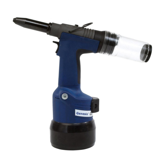
Avdel genesis g2 Instruction Manual
Hydro-pneumatic power tool
Hide thumbs
Also See for genesis g2:
- Instruction manual (106 pages) ,
- Fitting instructions manual (8 pages)

Related Manuals for Avdel genesis g2


Summary of Contents for Avdel genesis g2
- Page 1 I n s t r u c t i o n M a n u a l ® Genesis H y d ro - P n e u m a t i c P o w e r To o l...
-
Page 3: Table Of Contents
AND REMEDIES. ANY IMPLIED WARRANTY AS TO QUALITY, FITNESS FOR PURPOSE, OR MERCHANTABILITY ARE HEREBY SPECIFICALLY DISCLAIMED AND EXCLUDED BY AVDEL. Avdel UK Limited policy is one of continuous product development and improvement and we reserve the right to change the specification of any product without prior notice. - Page 4 Any modification undertaken by the customer to the tool/machine, nose assemblies, accessories or any equipment supplied by Avdel UK Limite. or their representatives, shall be the customer’s entire responsibility. Avdel UK Limited will be pleased to advise upon any proposed modification.
- Page 5 S p e c i f i c a t i o n s To o l S p e c i f i c a t i o n Air Pressure Minimum - Maximum 5-7 bar Free Air Volume Required @ 5.5 bar 2.1 litres Stroke...
-
Page 6: Part Numbering
R a n g e o f F a s t e n e r s ® nG2 is a hydro-pneumatic tool designed to place Avdel FASTENER SIZE ( breakstem fasteners at high speed making it ideal for batch or FASTENER flow-line assembly in a wide variety of applications throughout... -
Page 7: Air Supply
P u t t i n g i n t o S e r v i c e A i r S u p p l y All tools are operated with compressed air at an optimum pressure of 5.5 bar. We recommend the use of pressure regulators and filtering systems on the main air supply. -
Page 8: Fitting Instructions
N o s e A s s e m b l i e s F i t t i n g I n s t r u c t i o n s I M P O R T A N T The air supply must be disconnected when fitting or removing nose assemblies. -
Page 9: Nose Tips
Steel 3 / 16 0 74 98-01 401 12 .7 … 0 8 2 71213-20320 ® AVDEL 1 / 8 7 12 10-05 002 12 .7 … 0 3 9* … 0 3 9* 5 / 32 7 12 10-16 070 12 .7... -
Page 10: Avseal ® Ii
N o s e A s s e m b l i e s N o s e T i p s ® A V S E A L N O S E T I P S N O S E T I P ( m m ) F A S T E N E R NOSE b elow... -
Page 11: Nose Tips
N o s e A s s e m b l i e s N o s e T i p s To fit Nose Tips Type 2/3 or Nose Extension, the ‘T’ Adaptor 41 must be replaced with Jaw Spreader Housing 9*. •... -
Page 12: Type
PART Nº part nº 71210-15300 Al Alloy 1 2.7 ® 1 / 8 7 121 0-160 30 … 2 8 3 AVDEL ITEM DESCRIPTION PART Nº 1 / 8 Al Alloy O 7 121 0-160 31 1 2.7 … 2 8 4 Stainless Steel 1 2.7... -
Page 13: Stem Deflector
A c c e s s o r i e s S t e m D e f l e c t o r The stem deflector is a very simple alternative to the standard stem collector and allows access in restricted areas. To replace the stem collector with the stem deflector proceed as follows: Preparing the Base Tool for use with Stem Deflector The airline must be diconnected before any servicing or dismantling. -
Page 14: Swivel Heads
1 / 8 Al Alloy 07345 -0 3 300 5.08 1.1 7 0 73 40-00 229 … 2 8 3 AVDEL 0 734 5-033 01 1 / 8 Al Alloy O 07494 -0 3 600 0 749 4-036 01 5.08 1.1 7... -
Page 15: Preparing The Base Tool For Right-Angle And Straight
5. 0 8 1 . 1 7 07 3 4 0 -0 0 2 29 … 2 8 3 0 7 3 45 - 03 3 0 1 AVDEL ® … 2 8 4 1 / 8 Aluminium Alloy O... - Page 16 A c c e s s o r i e s The fitting and servicing procedures for both types of head are almost identical. Differences are clearly indicated. I M P O R T A N T PRIOR to fitting a swivel head, the base tool must be adapted. See Preparing the Base Tool opposite. The air supply must be disconnected when fitting or removing swivel heads.
- Page 17 A c c e s s o r i e s S w i v e l H e a d S e r v i c i n g I n s t r u c t i o n s Swivel heads should be serviced at weekly intervals.
-
Page 18: Safety Instructions
S e r v i c i n g t h e To o l I M P O R T A N T Read Safety Instructions on page 4. The employer is responsible for ensuring that tool maintenance instructions are given to the appropriate personnel. The operator should not be involved in maintenance or repair of the tool unless properly trained. - Page 19 S e r v i c i n g t h e To o l M o l y k o t e ® 5 5 m G r e a s e S a f e t y D a t a First Aid SKIN: Flush with water.
-
Page 20: Service Kit
S e r v i c i n g t h e To o l S e r v i c e K i t For an easy complete service, Avdel offers the complete service kit below. SERVICE KIT : 71210-99990 Spanners are specified in inches and across flats unless otherwise stated PART Nº... -
Page 21: Dismantling The Tool
S e r v i c i n g t h e To o l D i s m a n t l i n g t h e To o l Before dismantling the tool the oil must be emptied from it. •... -
Page 22: Pneumatic Piston Assembly
S e r v i c i n g t h e To o l P n e u m a t i c P i s t o n A s s e m b l y • Remove ‘ON/OFF’ valve assembly 62. •... -
Page 23: Rotary Valve
S e r v i c i n g t h e To o l R o t a r y Va l v e Dismantling • Using a 4mm pin punch (07900-00158) drive Trigger Pin 46 out and remove Trigger Assembly 33. •... - Page 24 S e r v i c i n g t h e To o l S t o p P l a t e A s s e m b l y ( 7 1 2 1 3 - 0 3 9 0 0 ) Assembly (see illustration below) •...
- Page 25 N o t e s...
- Page 26 G e n e r a l A s s e m b l y o f B a s e To o l 7 1 2 1 3 - 0 2 0 0 0...
- Page 27 P a r t s L i s t f o r 7 1 2 1 3 - 0 2 0 0 0...
-
Page 28: Oil Details
P r i m i n g Priming is ALWAYS necessary after the tool has been dismantled and prior to operating. It may also be necessary to restore the full stroke after considerable use, when the stroke may have been reduced and fasteners are not now being fully placed by one operation of the trigger. O i l D e t a i l s ®... -
Page 29: Priming Procedure
P r i m i n g P r i m i n g P ro c e d u r e I M P O R T A N T DISCONNECT THE TOOL FROM THE AIR SUPPLY OR SWITCH OFF AT VALVE 62. REMOVE NOSE ASSEMBLY OR SWIVEL HEAD COMPONENTS. - Page 30 † Page 16 if a swivel head is used instead of a nose assembly. Item numbers in bold refer to the general assembly drawing and parts list on pages 26 and 27. Other symptoms or failures should be reported to your local Avdel authorised distributor or repair centre.
- Page 31 D e c l a r a t i o n o f C o n f o r m i t y We, Avdel UK Limited, Watchmead Industrial Estate, Welwyn Garden City, Herts, AL7 1LY declare under our sole responsibility that the product: Model nG2 Serial No.
- Page 32 Fax: +1 704 888-0258 Manual No. Issue Change Note No. Email: infoAvdel-USA@acument.com 05/370 05/519 07900-00841 06/536 07/044 07/103 07/174 Avdel®, Avdel® SR, Avex®, Avibulb®, Avinox®, Avseal®, Bulbex®, Interlock®, Genesis®, MBC®, MBC®/LC, Monobolt®, Stavex®, T-Lok®, TLR® are trademarks of Avdel UK Limited. www.avdel-global.com...
Need help?
Do you have a question about the genesis g2 and is the answer not in the manual?
Questions and answers