Table of Contents
Advertisement
Advertisement
Table of Contents

Related Manuals for MSI X58 PRO MS-7522


Summary of Contents for MSI X58 PRO MS-7522
- Page 1 X58 Pro Series MS-7522 (v3.X) Mainboard G52-75221X4...
-
Page 2: Trademarks
Alternatively, please try the following help resources for further guidance. Visit the MSI website for FAQ, technical guide, BIOS updates, driver updates, an d ot h er i n f orm at i on: h t t p: / / g l o ba l . -
Page 3: Safety Instructions
Safety Instructions Always read the safety instructions carefully. Keep this User’s Manual for future reference. Keep this equipment away from humidity. Lay this equipment on a reliable flat surface before setting it up. The openings on the enclosure are for air convection hence protects the equip- ment from overheating. -
Page 4: Fcc-B Radio Frequency Interference Statement
FCC-B Radio Frequency Interference Statement T h is eq uip men t h as been tested and found to c omply with the limits for a Class B digital device, pursuant to Part 15 of the FCC Rules. These limits are designed to provide reasonable protection against harmful interference in a residential installation. -
Page 5: Weee (Waste Electrical And Electronic Equipment) Statement
WEEE (Waste Electrical and Electronic Equipment) Statement... -
Page 8: Table Of Contents
CONTENTS Copyright Notice ......................ii Trademarks ........................ii Revision History ......................ii Technical Support ......................ii Safety Instructions ......................iii FCC-B Radio Frequency Interference Statement ............iv W EEE (Waste Electrical and Electronic Equipment) Statement ........v Chapter 1. Getting Started ..................1-1 Mainboard Specifications ................... 1-2 Mainboard Layout .................... - Page 9 Hardware Setup ....................A-19 Appendix B Overclocking Center ............... B-1 Activating Overclocking Center ................. B-2 System Info ......................B-3 DOT ........................B-5 Appendix C Intel ICH10R SATA RAID ..............C-1 ICH10R Introduction ..................... C-2 BIOS Configuration ....................C-3 Installing Driver ....................C-9 Installing Software ....................
-
Page 10: Chapter 1. Getting Started
Getting Started Chapter 1 Getting Started Thank you for choosing the X58 Pro (MS-7522 v3.X) ATX mainboard. The X58 Pro mainboard is based on in inb ® Intel X58 & ICH10R chipsets for optimal sys tem ® ef ficienc y. Designed to fit the advanc ed Intel LGA1366 processor, the X58 Pro delivers a high per- formance and professional desktop platform solution. -
Page 11: Mainboard Specifications
M S-7522 M ainboard Mainboard Specifications Processor Support ® - Intel i7 processors in the LGA1366 package (For the latest information about CPU, please visit http://global.msi.com.tw/index.php?func=cpuform2) Supported QPI - Up to 6.4 GT/s Chipset ® - North Bridge: Intel X58 chipset ®... - Page 12 Getting Started Connectors Back panel - 1 PS/2 mouse port - 1 PS/2 keyboard port - 1 Optical S/PDIF-Out port - 1 1394 port - 1 eSATA port - 6 USB 2.0 Ports - 1 LAN jack - 6 flexible audio jacks On-Board Pinheaders / Connectors - 3 USB 2.0 connectors - 1 1394 connector...
-
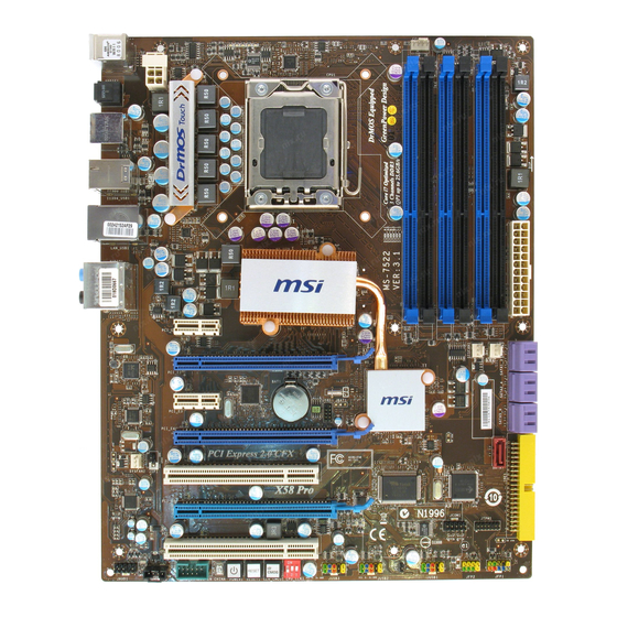
Page 13: Mainboard Layout
M S-7522 M ainboard Mainboard Layout JPWR2 CPUFAN1 T: mouse B: keyboard Optical SPDIF jack T: USB ports B: SATA port T: 1394 port B: U SB ports T: LAN Jack B: U SB ports Line-In Line-O ut T: RS-Out Intel M: C S-O ut B: SS-Out... -
Page 14: Packing Checklist
Getting Started Packing Checklist Back IO Shield MSI Driver/Utility CD MSI motherboard Power Cable SATA Cable able able IDE Cable User’s Guide external SATA Cable 1394 Bracket(optional) and Quick Guide (optional) CrossFire Video Link Cable * The pictures are for reference only and may vary from the packing contents of the... -
Page 15: Chapter 2. Hardware Setup
Hardware Setup Chapter 2 Hardware Setup This chapter provides you with the information about hardware setup procedures. While doing the installation, doin doing be careful in holding the components and follow the installation procedures. For some components, if you install in the wrong orientation, the components will not work properly. -
Page 16: Quick Components Guide
M S-7522 M ainboard Quick Components Guide CPUFAN1, p.2-16 JPWR2, p.2-11 CPU, p.2-3 DDR3, p.2-7 Back Panel, p.2-12 JPWR1, p.2-11 SYSFAN1/3, p.2-16 PCI_E, p.2-22 SATA, p.2-15 JSP1, p.2-20 SYSFAN2, IDE1, p.2-14 p.2-16 PCI, JTPM1, p.2-18 p.2-25 JFP2, JFP1, CPU_CLK1, p.2-17 p.2-26 JCOM1, p.2-17 CLR_CMOS1,... -
Page 17: Cpu (Central Processing Unit)
W hen you are installing the CPU, make sure to install the cooler to prevent overheating. If you do not have the CPU cooler, consult your dealer before turning on the computer. For the latest information about CPU, please visit http://global.msi.com.tw/index.php? func=cpuform2 Important Overheating Overheating will seriously damage the CPU and system. - Page 18 M S-7522 M ainboard CPU & Cooler Installation W hen you are installing the CPU, make sure the CPU has a cooler attached on the top to prevent overheating. Meanwhile, do not forget to apply some thermal paste on CPU before installing the heat sink/cooler fan for better heat dispersion. Follow the steps below to install the CPU &...
- Page 19 Hardware Setup 5. Visually inspect if the CPU is seated 6. C over t h e l oad p l at e on t o t h e well into the socket. If not, take out package. the CPU with pure vertical motion and reinstall.
- Page 20 M S-7522 M ainboard 9. Align the holes on the mainboard with 10.Press the four hooks down to fas- the heatsink. Push down the cooler ten the cooler. until its four clips get wedged into the holes of the mainboard. 11.
-
Page 21: Memory
Hardware Setup Memory These DIMM slots are used for installing memory modules. For more information on compatible components, please visit http://global.msi.com. tw/index.php?func=testreport DDR3 240-pin, 1.5V 48x2=96 pin 72x2=144 pin Dual-Channel: Channel A in SKYBLUE; Channel B in PINK Memory Population Rules Please refer to the following illustrations for memory population rules. - Page 22 M S-7522 M ainboard Three-Channel mode In Three-Channel mode, the memory modules can transmit and receive data with three data bus lines simultaneously. Enabling Three-Channel mode can enhance the best system performance. W hen you have three or more memory modules, please always insert them as the way 3/ 4/ 5/ 6 (shown in below) to get the best system performance.
- Page 23 Hardware Setup Important - DDR3 memory modules are not interchangeable with DDR2 and the DDR3 standard is not backwards compatible. You should always install DDR3 memory modules in the DDR3 DIMM slots. - In Three/ Dual-Channel mode, make sure that you install memory modules of the same type and density in different channel DIMM slots.
-
Page 24: Installing Memory Modules
M S-7522 M ainboard Installing Memory Modules 1. The memory module has only one notch on the center and will only fit in the right orientation. 2. Insert the memory module vertically into the DIMM slot. Then push it in until the golden finger on the memory module is deeply inserted in the DIMM slot. -
Page 25: Power Supply
Hardware Setup Power Supply ATX 24-Pin Power Connector: JPWR1 pin 13 This connector allows you to connect an ATX 24-pin power supply. To connect the ATX 24-pin power supply, make sure the plug of the power supply is inserted in the proper orientation and the pins are aligned. -
Page 26: Back Panel
M S-7522 M ainboard Back Panel USB Ports 1394 Port Mouse Line-In RS-Out Keyboard Line-Out CS-Out eSATA Port Optical SS-Out USB Ports USB Ports S/PDIF-Out port M ouse/Keyboard ® ® The standard PS/2 mouse/keyboard DIN connector is for a PS/2 mouse/keyboard. - Page 27 Hardware Setup Audio Ports These audio connectors are used for audio devices. It is easy to differentiate be- tween audio effects according to the color of audio jacks. Line-In (Blue) - Line In is used for external CD player, tapeplayer or other audio devices.
-
Page 28: Connectors
M S-7522 M ainboard Connectors IDE Connector: IDE1 This connector supports IDE hard disk drives, optical disk drives and other IDE devices. Important If you install two IDE devices on the same cable, you must configure the al all drives separately to master / slave mode by setting jumpers. Refer to IDE dev ic e’s doc umentation s upplied by the vendors for jumper s etting instructions. - Page 29 Hardware Setup Serial ATA Connector: SATA1~ 7 This connector is a high-speed Serial ATA interface port. Each connector can connect to one Serial ATA device. SATA1~6 stack SATA connectors are supported by ICH10R SATA1_3 SATA2_4 SATA5_6 SATA7 is supported by SATA7 JM B363 Important...
- Page 30 M S-7522 M ainboard Fan Power Connectors: CPUFAN, SYSFAN1~3 The fan power connectors support system cooling fan with +12V. W hen connecting the wire to the connectors, always note that the red wire is the positive and should be connected to the +12V; the black wire is Ground and should be connected to GND. If the mainboard has a System Hardware Monitor chipset on-board, you must use a specially designed fan with speed sensor to take advantage of the CPU fan control.
-
Page 31: Serial Port Connector Jcom1
Hardware Setup Front Panel Connectors: JFP1, JFP2 These connectors are for electrical connection to the front panel switches and LEDs. ® The JFP1 is compliant with Intel Front Panel I/O Connectivity Design Guide. JFP1 Pin Definition SIGNAL DESCRIPTION Power Power Switch HD_LED + Hard disk LED pull-up... - Page 32 M S-7522 M ainboard TPM Module Connector: JTPM1 This connector connects to a TPM (Trusted Platform Module) module (optional). Please refer to the TPM security platform manual for more details and usages. JTPM 1 Signal Description Signal Description LCLK LPC clock 3V_STB 3V standby power LRST#...
- Page 33 Hardware Setup Front USB Connector: JUSB1/ JUSB2/ JUSB3 ® These connectors, compliant with Intel I/O Connectivity Design Guide, is ideal for connecting high-speed USB interface peripherals such as USB HDD, digital cameras, M P3 players, printers, modems and the like. Pin Definition SIGNAL SIGNAL...
- Page 34 M S-7522 M ainboard Front Panel Audio Connector: JAUD1 This connector allows you to connect the front panel audio and is compliant with ® Intel Front Panel I/O Connectivity Design Guide. JAUD1 HD Audio Pin Definition SIGNAL DESCRIPTION MIC_L Microphone - Left channel Ground MIC_R Microphone - Right channel...
-
Page 35: Buttons
Hardware Setup Buttons The motherboard provides the following buttons for you to set the computer’s function. This section will explain how to change your motherboard’s function through the use of button. Power Button: POWER1 This power button is used to turn-on or turn-off the system. Press the button to turn- on or turn-off the system. -
Page 36: Slots
M S-7522 M ainboard Slots PCI (Peripheral Component Interconnect) Express Slot The PCI Express slot supports the PCI Express interface expansion card. The PCI Express 2.0 x16 supports up to 8.0 GB/s transfer rate. The PCI Express 2.0 x4 supports up to 2.0 GB/s transfer rate. The PCI Express 1.0 x1 supports up to 250 MB/s transfer rate. - Page 37 Hardware Setup ATI CrossFireX (Multi-GPU) Technology ATI CrossFireX is the ultimate multi-GPU performance gaming platform. Enabling game-dominating power, ATI CrossFireX technology enables two or more discrete graphics processors to work together to improve system performance. ATI CrossFireX technology allows you to expand your system’ss graphics capabilities. It allows you the ability to scale your system’s graphics horsepower as you need it, supporting up to two or more ATI Radeon HD graphics cards, making this the most scalable gaming...
- Page 38 M S-7522 M ainboard 3.W hen all of the hardware and software has been properly set up and installed, reboot the system. After entering the O.S., click the “Catalyst™ Control Center” icon on the desktop. There is a setting in the Catalyst™ Control Center that needs to be enabled for CrossFireX™...
- Page 39 Hardware Setup PCI (Peripheral Component Interconnect) Slot The PCI slot supports LAN card, SCSI card, USB card, and other add-on cards that comply with PCI specifications. 32-bit PCI Slot Important When adding or removing expansion cards, make sure that you unplug the r e r power supply first.
-
Page 40: Switch
M S-7522 M ainboard Switch Hardware Overclock Base clock Switch: CPU_CLK1 You can overclock the Base clock to increase the processor frequency by changing this switch. Follow the instructions below to set the base clock. 1 2 3 1 2 3 1 2 3 133 MHz (default) 166 MHz... -
Page 41: Led Status Indicators
Hardware Setup LED Status Indicators DIMM warning LED CPU Phase LEDs PCIE LED PCIE LED PCIE LED PCIE LED PCIE LED PCI LED PCI LED Power LED Suspend LED CPU Phase LEDs These LEDs indicate the current CPU power phase mode. Follow the instructions below to read. -
Page 42: Power Led
M S-7522 M ainboard DIMM Warning LED Lights red when the incorrect memory installed into DIMM_C0/ DIMM_C1 (the DIMMs of 3rd channel). Power LED Lights green when the system is in power-on(S0/S1) status. Suspend LED Lights yellow when the system is suspended (S3/S4/S5 ). PCIE and PCI LEDs Lights blue when the slots is functional. -
Page 43: Chapter 3 Bios Setup
BIOS Setup Chapter 3 BIOS Setup This chapter provides information on the BIOS Setup program and allows you to configure the system for optimum use. You may need to run the Setup program when: An error message appears on the screen during the system booting up, and requests you to run SETUP. -
Page 44: Entering Setup
M S-7522 M ainboard Entering Setup Power on the computer and the system will start POST (Power On Self Test) process. W hen the message below appears on the screen, press <DEL> key to enter Setup. Press DEL to enter SETUP If the message disappears before you respond and you still wish to enter Setup, restart the system by turning it OFF and On or pressing the RESET button. -
Page 45: Control Keys
BIOS Setup Control Keys <↑> Move to the previous item <↓> Move to the next item <←> Move to the item in the left hand <→> Move to the item in the right hand <Enter> Select the item <Esc> Jumps to the Exit menu or returns to the main menu from a submenu <+/PU>... -
Page 46: The Main Menu
M S-7522 M ainboard The Main Menu Standard CM OS Features Use this menu for basic system configurations, such as time, date etc. igur Advanced BIOS Features ® Use this menu to setup the items of AMI special enhanced features. Integrated Peripherals iphe Use this menu to specify your settings for integrated peripherals. - Page 47 BIOS Setup M-Flash Use this menu to read/ flash the BIOS from USB mediaevice. Load Fail-Safe Defaults Use this menu to load the default values set by the BIOS vendor for stable system performance. Load Optimized Defaults Use this menu to load the default values set by the mainboard manufacturer specifi- cally for optimal performance of the mainboard.
-
Page 48: Standard Cmos Features
M S-7522 M ainboard Standard CMOS Features The items in Standard CMOS Features Menu includes some basic setup items. Use the arrow keys to highlight the item and then use the <PgUp> or <PgDn> keys to select the value you want in each item. Date (MM:DD:YY) This allows you to set the system to the date that you want (usually the current date). - Page 49 BIOS Setup Device / Vendor / Size It will showing the device information that you connected to the SATA connector. Important SATA1~7, IDE Primary Master/ Slave & E-SATA1 are appearing when you appe r i r connect the HD devices to the IDE/ SATA connector on the mainboard. System Information Press <Enter>...
-
Page 50: Advanced Bios Features
M S-7522 M ainboard Advanced BIOS Features Full Screen Logo Display This item enables you to show the company logo on the bootup screen. Options are: [Enabled] Shows a still image (logo) on the full screen at boot. [Disabled] Shows the POST messages at boot. Quick Booting Setting the item to [Enabled] allows the system to boot within 10 seconds since it will bl ble... - Page 51 BIOS Setup Primary Graphic’s Adapter This setting specifies which graphics card is your primary graphics adapter. PCI Latency Timer This item controls how long each PCI device can hold the bus before another takes over. W hen set to higher values, every PCI device can conduct transactions for a longer time and thus improve the effective PCI bandwidth.
- Page 52 M S-7522 M ainboard Set Limit CPUID MaxVal to 3 The Max CPUID Value Limit is designed to limit the listed speed of the processor to older operating systems. Overspeed Protection Overspeed Protection function can monitor the current CPU draws as well as its power consumption.
-
Page 53: Integrated Peripherals
BIOS Setup Integrated Peripherals USB Controller This setting allows you to enable/disable the onboard USB controller. di dis bl ble USB Device Legacy Support Select [Enabled] if you need to use a USB-interfaced device in the operating system. Onboard LAN Controller This item is used to enable/disable the onboard LAN controller. - Page 54 M S-7522 M ainboard PCI IDE BusMaster This item allows you to enable/ disable BIOS to used PCI busmastering for reading/ writing to IDE drives. On-Chip SATA Controller These items allow users to enable or disable the SATA controller. RAID M ode This item allows you to configure SATA mode.
-
Page 55: Power Management Setup
BIOS Setup Power Management Setup Important S3-related functions described in this section are available only when your ribed r ibed ibed ibed BIOS supports S3 sleep mode. l e l ode. ode. ACPI Function This item is to activate the ACPI (Advanced Configuration and Power Management Interface) Function. - Page 56 M S-7522 M ainboard Re-Call VGA BIOS From S3 W hen ACPI Standby State is set to [S3], users can select the options in this field. Selecting [Yes] allows BIOS to call VGABIOS to initialize the VGA card when system wakes up (resumes) from S3 sleep state.
- Page 57 BIOS Setup Resume by PCI-E Device W hen set to [Enabled], the feature allows your system to be awakened from the power saving modes through any event on PCIE device. Resume by RTC Alarm The field is used to enable or disable the feature of booting up the system on a scheduled time/date.
-
Page 58: H/W Monitor
M S-7522 M ainboard H/W Monitor Chassis Intrusion The field enables or disables the feature of recording the chassis intrusion status and issuing a warning message if the chassis is once opened. To clear the warning message, set the field to [Reset]. The setting of the field will automatically return to T Th [Enabled] later. -
Page 59: Bios Setting Password
BIOS Setup BIOS Setting Password W hen you select this function, a message as below will appear on the screen: Type the password, up to six characters in length, and press <Enter>. The password typed now will replace any previously set password from CMOS memory. You will be prompted to confirm the password. -
Page 60: Cell Menu
M S-7522 M ainboard Cell Menu Important Change these settings only if you are familiar with the chipset. Current Core / DRAM / QPI Frequency These items show the current clocks of CPU and Memory speed. Read-only. 3-18... - Page 61 BIOS Setup CPU Specifications Press <Enter> to enter the sub-menu and the following screen appears. This sub-menu displays the informations of installed CPU. CPU Technology Support Press <Enter> to enter the sub-menu and the following screen appears. f fo This sub-menu displays the technologies that the installed CPU supported. Intel EIST The Enhanced Intel SpeedStep technology allows you to set the performance level of the microprocessor whether the computer is running on battery or AC power.
- Page 62 M S-7522 M ainboard Intel Turbo Boost tech This item will appear when you install a CPU include Intel Turbo Boost technology. This item is used to enable/ disable Intel Turbo Boost technology. For further information please refer to Intel's official website. \ Adjusted Core Frequency (M Hz) It shows the adjusted CPU frequency (Base clock x Ratio).
- Page 63 BIOS Setup Advance DRAM Configuration Press <Enter> to enter the sub-menu and the following screen appears. 1N/2N M emory Timing This item controls the SDRAM command rate. Select [1N] makes SDRAM signal controller to run at 1N (N=clock cycles) rate. Selecting [2N] makes SDRAM signal controller run at 2N rate.
- Page 64 M S-7522 M ainboard ClockGen Tuner Press <Enter> to enter the sub-menu and the following screen appears. CPU / PCI Express Amplitude Control These items are used to select the CPU/ PCI Express clock amplitude. CPU CLK Skew/ IOH CLK Skew These items are used to select the CPU/ IOH chipset clock skew.
- Page 65 BIOS Setup are reduced to flatter curves. If you do not have any EMI problem, leave the setting at Disabled for optimal system stability and performance. But if you are plagued by EMI, set to Enabled for EMI reduction. Remember to disable Spread Spectrum if you are overclocking because even a slight jitter can introduce a temporary boost in clock speed which may just cause your overclocked processor to lock up.
-
Page 66: Cpu And Memory Clock Overclocking
M S-7522 M ainboard CPU and Memory Clock Overclocking The Base Clock, Memory Ratio items for you to overclock the CPU and the Memory. Please refer to the descriptions of these fields for more information. Important 1. CPU Speed = Base clock * CPU Ratio 2. -
Page 67: User Setting
BIOS Setup User Settings Save Settings 1/ 2/ 3/ 4 These items are used to save the settings set by yourself to CMOS. tt tting ings Load Settings 1/ 2/ 3/ 4 These items are available after you save your settings in Save Settings 1/ 2/ 3/ 4 items , and are used to load the settings from CMOS. -
Page 68: M-Flash
M S-7522 M ainboard M-Flash == BIOS Update or Boot 2nd BIOS From USB drive== M -Flash function as M-Flash funcion allows you to flash BIOS from USB drive/ storage drive (FAT/ FAT32 format only), or allows the system to boot from the BIOS file inside USB drive (FAT/ FAT32 format only). - Page 69 BIOS Setup Important 1. Please refer to the block diagram below about the M-Flash function. Set [BIOS Update] or [USB Boot] in "M-Flas h fun ction as " field Select BIOS fi le from the ro ot directory of USB/ Storage drive (FAT/FAT32 format only) in "L oad BIOS sou rce file from"...
- Page 70 M S-7522 M ainboard == Backup BIOS to USB drive == The following fields are used to read the onboard BIOS ROM data, and save it to USB drive/ storage drive. Save File to Selected Device Please setup a specific folder in specific USB drive/ storage drive to save BIOS file from BIOS ROM chip data.
-
Page 71: Load Fail-Safe/ Optimized Defaults
BIOS Setup Load Fail-Safe/ Optimized Defaults The two options on the main menu allow users to restore all of the BIOS settings to the default Fail-Safe or Optimized values. The Optimized Defaults are the default values set by the mainboard manufacturer specifically for optimal performance of the mainboard. -
Page 72: Appendix A Realtek Audio
Realtek Audio Appendix A Realtek Audio The Realtek ALC888S provides 10-channel DAC that simultaneously supports 7.1 sound playback and 2 chan- nels of independent s tereo s ound output (multiple streaming) through the Front-Out-Left and Front-Out- Right channels. -
Page 73: Installing The Realtek Hd Audio Driver
The following illustrations are based on W indows XP environment and could look slightly different if you install the drivers in different operating systems. 1. Insert the MSI DVD into the DVD-ROM drive. The setup screen will automati- cally appear. 2. Click Realtek HD Audio Drivers. - Page 74 Realtek Audio 3. Click Next to install the Realtek High Definition Audio Driver. Click here 4. Click Finish to restart the system. S el ec t t hi s option Click here...
-
Page 75: Software Configuration
M S-7522 M ainboard Software Configuration After installing the audio driver, you are able to use the 2-, 4-, 6- or 8- channel audio feature now. Click the audio icon from the system tray at the lower-right corner of the screen to activate the HD Audio Configuration. It is also available to enable the HD Audio Configuration by clicking the Realtek HD Audio M anager from the Control Panel. -
Page 76: Sound Effect
Realtek Audio Sound Effect Here you can select a sound effect you like from the Environment list. Environment Simulation You will be able to enjoy different sound experience by pulling down the arrow, di diff ffe several kinds of sound effect will be shown for selection. Realtek HD Audio Sound ff ffe Manager also provides five popular settings “Stone Corridor”, “Bathroom”, “Sewer pipe”, “Arena”... - Page 77 M S-7522 M ainboard Equalizer Selection Equalizer frees users from default settings; users may create their owned preferred settings by utilizing this tool. 10 bands of equalizer, ranging from 100Hz to 16KHz. Save Reset The settings are saved 10 bands of equalizer permanently for future would go back to the de- fault setting...
- Page 78 Realtek Audio Frequently Used Equalizer Setting Realtek recognizes the needs that you might have. By leveraging our long experience at audio field, Realtek HD Audio Sound Manager provides you certain optimized equal- izer settings that are frequently used for your quick enjoyment. [How to Use It] Other than the buttons “Pop”...
- Page 79 M S-7522 M ainboard Mixer In the Mixer part, you may adjust the volumes of the rear and front panels individually. 1. Adjust Volume You can adjust the volume of the speakers that you plugged in front or rear panel by select the Realtek HD Audio rear output or Realtek HD Audio front output items.
- Page 80 Realtek Audio W hen you are playing the first audio source (for example: use W indows Media pl ple Player to play DVD/VCD), the output will be played from the rear panel, which is the default setting. Then you must to select the Realtek HD Audio front output from the scroll list first, and use a different program to play the second audio source (for example: use Winamp to play MP3 files).
- Page 81 M S-7522 M ainboard 3. Playback control Playback device Tool Mute This function is to let you freely decide which ports to output the sound. And this is essential when multi- streaming playback enabled. - Realtek HD Audio Rear Output tp t t p t - Realtek HD Audio Front Output...
- Page 82 Realtek Audio 4. Recording control Recording device Tool Mute -Back Line in/Mic, Front Line in -Realtek HD Audio Input M u te You may choose to mute single or multiple volume controls or to completely mute sound input. Tool - Show the following volume controls This is to let you freely decide which volume control items to be displayed.
- Page 83 M S-7522 M ainboard Audio I/O In this tab, you can easily configure your multi-channel audio function and speakers. You can choose a desired multi-channel operation here. a. Headphone for the common headphone b. 2CH Speaker for Stereo-Speaker Output c. 4CH Speaker for 4-Speaker Output d.
- Page 84 Realtek Audio Connector Settings Click to access connector settings. Disable front panel jack detection (option) Find no function on front panel jacks? Please check if front jacks on your system are so-called AC’97 jacks. If so, please check this item to disable front panel jack detection. M ute rear panel output when front headphone plugged in.
- Page 85 M S-7522 M ainboard S/PDIF Short for Sony/Philips Digital Interface, a standard audio file transfer format. S/PDIF allows the transfer of digital audio signals from one device to another without having to be converted first to an analog format. Maintaining the viability of a digital signal prevents the quality of the signal from degrading when it is converted to analog.
- Page 86 Realtek Audio Test Speakers You can select the speaker by clicking it to test its functionality. The one you select will light up and make testing sound. If any speaker fails to make sound, then check whether the cable is inserted firmly to the connector or replace the bad speakers with good ones.
- Page 87 M S-7522 M ainboard Microphone In this tab you may set the function of the microphone. Select the Noise Suppres- sion to remove the possible noise during recording, or select Acoustic Echo Can- cellation to cancel the acoustic echo during recording. Acoustic Echo Cancellation prevents playback sound from being recorded by microphone together with your sound.
-
Page 88: D Audio Demo
Realtek Audio 3D Audio Demo In this tab you may adjust your 3D positional audio before playing 3D audio applica- tions like gaming. You may also select different environment to choose the most suitable environment you like. A-17... - Page 89 M S-7522 M ainboard Information In this tab it provides some information about this HD Audio Configuration utility, including Audio Driver Version, DirectX Version, Audio Controller & Audio Codec. You may also select the language of this utility by choosing from the Language list. Also there is a selection Show icon in system tray.
-
Page 90: Hardware Setup
Realtek Audio Hardware Setup Connecting the Speakers W hen you have set the Multi-Channel Audio Function mode properly in the software utility, connect your speakers to the correct phone jacks in accordance with the setting in software utility. 2-Channel M ode for Stereo-Speaker Output Line In Line Out (Front channels) No function... - Page 91 M S-7522 M ainboard 4-Channel M ode for 4-Speaker Output Line In Line Out (Front channels) r on hann hann Line Out (Rear channels) No function No function A-20...
- Page 92 Realtek Audio 6-Channel M ode for 6-Speaker Output Line In Line Out (Front channels) r on hann hann Line Out (Rear channels) Line Out (Center and Subwoofer channel) No function A-21...
- Page 93 M S-7522 M ainboard 8-Channel M ode for 8-Speaker Output Line In Line Out (Front channels) r on hann hann Line Out (Rear channels) Line Out (Center and Subwoofer channel) Line Out (Side channels) Important To enable 7.1 channel audio-out function on Vista operating system, you have to install the Realtek Audio Driver.
-
Page 94: Appendix B Overclocking Center
Appendix B Overclocking Center Overclocking Center, the most useful and powerful utility that MSI has spent much research and efforts to develop, helps users to monitor or configure the hard- ware status of MSI Mainboard in windows, such as CPU clock, voltage, fan speed and temperature. -
Page 95: Activating Overclocking Center
Overclocking Center), it will have a short cut icon on the desktop, and a short cut path in your “Start-up” menu. You may double-click on each icon to activate Overclocking Center. short-cut icon on the desktop short-cut path in the start-up menu (path: Start-->Program-->MSI-->Overclocking Center-->Overclocking Center) -
Page 96: System Info
Overclocking Center System Info In the System Info screen, you can read the informations of mainboard/ memory/ PCI. Motherboard Click Motherboard to read the informations of mainboard, mainboard BIOS, installed CPU and installed graphics card. - Page 97 M S-7522 M ainboard Memory Click Memory to read the information of each memory DIMM slot. You can select a DIMM slot you want to read from the SPD list. Click PCI to read the information of devices on the mainboard. io ion...
-
Page 98: Dot
Overclocking Center Click DOT to enter the DOT screen. In DOT, you can select the basic setting to reach optimal perf ormance in Basic menu or you c an adjus t advanced values for overclocking in Advance menu. Basic In the Basic menu, it provides one default setting and five common settings for different environments. - Page 99 M S-7522 M ainboard Advance In the Advance menu, you can adjust the values for each environment setting/ default setting. Click the Cooling/ Silence/ Default/ Game/ Cinema button to enter it’s setting menu. Please refer to the following descriptions to adjust the values and save them.
- Page 100 Overclocking Center In each setting menu, you can select desired values for manual overclocking. Simply click the right side of the button which arranges an arrow sign, and a drop-down menu will appear below the button, then select a value. Click the arrow sign and t he d rop- down m en u will appear.
- Page 101 M S-7522 M ainboard After you adjust the values in setting menu, you can save it for future use. Click the Save button, and enter a name in the empty box. Then, click Save button again to save the settings. Important It provides you to save up to 20 user settings.
-
Page 102: Appendix C Intel Ich10R Sata Raid
Intel ICH10R SATA RAID Appendix C Intel ICH10R SATA RAID This appendix will assist users in configuring and en- igur abling RAID functionality on platforms tf tfo... - Page 103 M S-7522 M ainboard Introduction The ICH10R provides a hybrid solution that combines 6 independent SATAII ports for support of up to 6 Serial ATAII (Serial ATAII RAID) drives. Serial ATAII (SATAII) is the latest generation of the ATA interface. SATA hard drives deliver blistering transfer speeds up to 3 Gb/s.
-
Page 104: Bios Configuration
Intel ICH10R SATA RAID BIOS Configuration The Intel Matrix Storage Manager Option ROM should be integrated with the system BIOS on all motherboards with a supported Intel chipset. The Intel Matrix Stroage Manager Option ROM is the Intel RAID implementation and provides BIOS and DOS disk services. - Page 105 M S-7522 M ainboard After pressing the <Ctrl> and <I> keys simultaneously, the following window will appear: (1) Create RAID Volume Select option 1 “Create RAID Volume” and press <Enter> key. The following lu lume screen appears. Then in the Name field, specify a RAID Volume name and then press the <TAB>...
- Page 106 Intel ICH10R SATA RAID In the Disk field, press <Enter> key and the following screen appears. Use <Space> key to select the disks you want to create for the RAID volume, then click <Enter> key to finish selection. Then select the strip value for the RAID array by using the “upper arrow” or “down arrow”...
- Page 107 M S-7522 M ainboard Important Since you want to create two volumes (Intel Matrix RAID Technology), this default size (maximum) needs to be reduced. Type in a new size for the first volume. As an example: if you want the first volume to span the first half of the two disks, re-type the size to be half of what is shown by default.
- Page 108 Intel ICH10R SATA RAID (2) Delete RAID Volume Here you can delete the RAID volume, but please be noted that all data on RAID drives will be lost. Important If your system currently boots to RAID and you delete the RAID volume in the Intel RAID Option ROM, your system will become unbootable.
- Page 109 M S-7522 M ainboard (3) Reset Disks to Non-RAID Select option 3 Reset Disks to Non-RAID and press <Enter> to delete the RAID volume and remove any RAID structures from the drives. The following screen appears: Press <Y> key to accept the selection. Important 1.
- Page 110 Intel ICH10R SATA RAID (4) Recovery Volume Options Select option 4 Recovery Volume Options and press <Enter> to change recovery volume mode. The following screen appears: Recovery mode will change from Continuous Update to On-Request after you enable “Only Recovery Disk” or “Only Master Disk”. ”...
-
Page 111: Installing Driver
Please follow the instruction below to make an “Intel ® RAID Driver” for yourself. 1. Insert the MSI DVD into the DVD-ROM drive. 2. Click the “Browse DVD” on the Setup screen. 3. Copy all the contents in \\RAID\Intel\ICH10R\Floppy to a formatted floppy \\ \\R diskette. - Page 112 Intel ICH10R SATA RAID Existing Windows Vista/XP Driver Installation 1. Insert the MSI DVD into the DVD-ROM drive. 2. The DVD will auto-run and the setup screen will appear. 3. Under the Driver tab, click on Intel RAID Drivers.
-
Page 113: Installing Software
For this reason, you cannot remove or un-install this driver from the system after installation; however, you will have the ability to un-install all other non-driver components. Insert the MSI DVD and click on the Driver-> M ulti-Raid Drivers -> Intel RAID Drivers to install the software. Click on this item... - Page 114 Intel ICH10R SATA RAID The InstallShield Wizard will begin automatically for installation showed as following: Click on the Next button to proceed the installation in the welcoming window. in ins C-13...
- Page 115 M S-7522 M ainboard The window shows the components to be installed. Click Next button to continue. After reading the license agreement in the following window, click Yes button to continue. C-14...
- Page 116 Intel ICH10R SATA RAID The following window appears to show the Readme File Information. It shows the system requirements and installation information. Once the installation is complete, the following window appears. C-15...
-
Page 117: Raid Migration Instructions
M S-7522 M ainboard RAID Migration Instructions The Intel Matrix Storage Console offers the flexibility to upgrade from a single Serial ATA (SATA) hard drive to RAID configuration when an additional SATA hard drive is added to the system. This process will create a new RAID volume from an existing disk. -
Page 118: Create Raid Volume From Existing Disk
Intel ICH10R SATA RAID Create RAID Volume from Existing Disk To create a RAID volume from an existing disk, choose Action --> Create RAID Volume from Existing Hard Drive. The Create RAID Volume from Existing Hard Drive Wizard pops up to lead you for the following procedure. - Page 119 M S-7522 M ainboard (1) Configure Volume Here you can configure the new RAID volume by entering the volume name, selecting the RAID level and strip size. RAID Volume Name: A desired RAID volume name needs to be typed in where the ‘Volume_0000’ text currently appears above.
- Page 120 Intel ICH10R SATA RAID expensive (requiring read-in prior to write, in order to be able to calculate the correct parity information), or similar to RAID-1 writes. The write efficiency depends heavily on the amount of memory in the machine, and the usage pattern of the array.
- Page 121 M S-7522 M ainboard (3) Select Member Hard Drive(s) Then select the member disk (the target disk) that you wish to use and then click “- -->” to move it to the Selected field. Then click Next to continue. Please note that the existing data on the selected hard drive(s) will be deleted permanently.
- Page 122 Intel ICH10R SATA RAID (4) Specify Volume Size Specify the amount of available array space to be used by the new RAID volume. You may enter the amount in the space or use the slider to specify. It is recommended you use 100% of the available space for the optimized usage.
- Page 123 M S-7522 M ainboard (6) Start Migration The migration process may take up to two hours to complete depending on the size of the disks being used and the strip size selected. A dialogue window will appear stating that the migration process may take considerable time to complete, meanwhile a popup dialogue at the taskbar will also show the migration status.
-
Page 124: Recovery Volume Creation
Intel ICH10R SATA RAID Recovery Volume Creation A recovery volume can be created using either Basic mode or Advanced mode in the Intel Matrix Storage Console. Recovery Volume in Basic Mode Creation Important Creating a recovery volume will permanently delete any existing data on the drive selected as the recovery drive. - Page 125 M S-7522 M ainboard Recovery Volume in Advanced Mode Creation Important Creating a recovery volume will permanently delete any existing data on the drive selected as the recovery drive. Back up all important data before beginning these steps. To create a recovery volume in Advanced mode, use the following steps: (1) Open the Intel Matrix Storage Console.
- Page 126 Intel ICH10R SATA RAID (6) Select a hard drive to be used as the master hard drive for the recovery volume. (7) Select a hard drive to be used as the recovery hard drive for the recovery volume. C-25...
- Page 127 M S-7522 M ainboard (8) Select an update policy. (9) Select Finish to begin recovery volume creation. C-26...
-
Page 128: Degraded Raid Array
Intel ICH10R SATA RAID Degraded RAID Array A RAID 1, RAID 5 or RAID 10 volume is reported as degraded when one of its hard drive members fails or is temporarily disconnected, and data mirroring is lost. As a result, the system can only utilize the remaining functional hard drive member. To re- establish data mirroring and restore data redundancy, refer to the procedure below that corresponds to the current situation. - Page 129 M S-7522 M ainboard 5. Exit Intel RAID Option ROM, and then reboot to W indows system. 6. W hen prompted to rebuild the RAID volume, click 'Yes'. 7. The Intel(R) Storage Utility will be launched. Right-click the new hard drive and select 'Rebuild to this Disk'.
Need help?
Do you have a question about the X58 PRO MS-7522 and is the answer not in the manual?
Questions and answers