MGE UPS Systems EX 11RT Installation And User Manual
Mge ups systems, inc. user manual power supply ex 5rt / ex 7rt/ ex 11rt
Hide thumbs
Also See for EX 11RT:
- Installation and user manual (76 pages) ,
- Quick start manual (8 pages)

Related Manuals for MGE UPS Systems EX 11RT


Summary of Contents for MGE UPS Systems EX 11RT
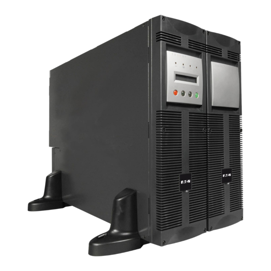
- Page 1 . m g e u p s . c o m EX 5RT / EX 7RT/ EX 11RT System Installation and User Manual 86-86000-00 A01...
-
Page 2: Important Safety Instructions
EX 5/7/11 RT System IMPORTANT SAFETY INSTRUCTIONS SAVE THESE INSTRUCTIONS – This manual contains important instructions for MGE UPS SYSTEMS, INC. products that must be followed during operation and maintenance of the equipment. WARNING Opening enclosures expose hazardous voltages. Always refer service to qualified personnel only. -
Page 3: Special Precautions
Safety of Persons ◗ The UPS has its own internal power source (the battery). Consequently, the power outlets may be energized even if the UPS is disconnected from the AC power source. ◗ The UPS must be properly grounded. ◗ The battery supplied with the UPS contains small amounts of toxic materials. -
Page 4: Caution: Record All Serial Numbers
ADDITIONAL MODULES SERIAL NUMBERS: ____________________________ ____________________________ ____________________________ ____________________________ ____________________________ ____________________________ ____________________________ ____________________________ ____________________________ ____________________________ NUMBERS IF SERVICE IS REQUIRED! EX 7RT System ______________________________ ______________________________ ______________________________ ______________________________ ______________________________ ______________________________ ______________________________ ______________________________ ______________________________ ______________________________ CAUTION: Record all serial numbers! EX 11RT System 86-86000-00 A01... -
Page 5: Revision History
E X 5 RT / E X 7 RT / E X 1 1 RT S y s t e m I n s t a l l a t i o n a n d U s e r M a nu a l R ev i s i o n : A 0 0 Copyright © 2004 MGE UPS SYSTEMS, INC. All rights reserved. Printed in U.S.A. MGE UPS SYSTEMS, INC. - Page 6 EX 5/7/11 RT System (This page left blank intentionally) 86-86000-00 A01...
-
Page 7: Table Of Contents
section description ......... . .page IMPORTANT SAFETY INSTRUCTIONS . - Page 8 EX 5/7/11 RT System Section 2 Setup and Installation section description ......... . .page Scope Unpacking and Parts Check .
-
Page 9: Warranty And Product Registration
Section 4 Maintenance section description ......... . .page Scope Information Technology (IT) Network and Industrial Operating Modes . - Page 10 2-1: Contents of Standard HV EX 5RT (PN 86050) / EX 7RT (PN 86070) / EX 11RT (PN 86110) System....2 — 3 2-2: Tower Configuration of Standard System and Optional Transformer Module.
- Page 11 Figures (continued) figure description ..........page 3-1: Initial Startup Display.
- Page 12 EX 5/7/11 RT System (This page left blank intentionally) 86-86000-00 A01 c vi...
-
Page 13: Introduction
Thank you for selecting an MGE UPS SYSTEMS, INC. (MGE) product to protect your electrical equipment. The product you selected is a part of the EX RT series. The EX RT series is a family of Uninterruptible Power Supply (UPS) designed to provide safe, and reliable AC power backup for sensitive electrical equipment. To discover the entire range of MGE products, we invite you to visit our website at www.mgeups.com or contact your representative... -
Page 14: Ex Rt Model Descriptions And Contents
HV EX 7RT Network Pack 7kVA 86070-01 LV EX 7RT 7kVA 86072-01 LV EX 7RT Network Pack 11kVA 86110 HV EX 11RT 11kVA 86112 HV EX 11RT Network Pack 11kVA 86110-01 LV EX 11RT 11kVA 86112-01 LV EX 11RT Network Pack 1 —... -
Page 15: Optional Accessories (See Section 1.5 For Description)
Table 2: Optional Accessories (See section 1.5 for description) Part Number 86001 86002 86005 86006 86008 86009 86010 86012 86013 86-86000-00 A01 Description Rail Kit for Power Module EX 5/7/11 RT Rail Kit for Battery/Transformer/CLA Module Battery Integration Kit with Casters Battery Extension Cable Kit Battery Chassis Empty EXB RT W/EPO I/O Box 5/7kVA UL/US... -
Page 16: And Optional Transformer Module
EX 5/7/11 RT System System Electrical Characteristics Table 3: Power Module Ratings Part Number 86055 Apparent Power, kVA Active Power, kW Input Current, A 25/24/23/ 22/21/20 Input Voltage, VAC 200/208/220/ 230/240/250 Output Current, A 25/24/23/ 22/21/20 Output Voltage, VAC 200/208/220/ 230/240/250 CAUTION Power Module is factory configured at 208Vac, 60 Hz input and output. -
Page 17: Transformer Module
Model Dimensions EX 5RT/7RT (3U) 5.16” x 17.49” x 25” (131 x 444 x 635mm) EX 11RT (3U) 5.16” x 17.49” x 25” (131 x 444 x 635mm) EXB 5 RT/ 7 RT (3U) 5.16” x 17.49” x 25” (131 x 444 x 635mm) EXB 11RT (3U) 5.16”... -
Page 18: Rear Panel Of The Battery Module
Power Module EX 5/7/11 RT EX 5RT Power Module part number 86055 EX 7RT Power Module part number 86075 EX 11RT Power Module part number 86115 Figure 1-3: Rear panel of the Power Module. 1.3.2 Battery Module EXB 5/7/11 RT With Emergency Power Off (EPO) Function Figure 1-4: Rear Panel of the Battery Module. -
Page 19: Rear Panel Of The Optional Transformer Module. (Pn 86003)
1.3.3 EX RT Transformer Module Figure 1-5: Rear Panel of the optional Transformer Module. (PN 86003) Load 4: 4 NEMA 5-15/20R Load 4 Circuit Breaker AC Input Transformer I/O Box AC Output Transformer Protect Breaker Display and Control Panel Figure 1-6: View of typical control panel interface. E X 1 1 R T 86-86000-00 A01 Load 3: 1 NEMA L6-30R... -
Page 20: Rack Mounting
EX 5/7/11 RT System Optional Accessories Optional Accessories describes the options available for upgrades and enhancement of the EX 5/7/11RT system. Detailed installation of the unit is described in following sections. To ensure a successful installation, all procedures should be followed in their correct sequence. Note that any unauthorized installation may cause damage to the UPS(s) and void the MGE warranty. -
Page 21: Typical Back-Up Time With Multiple Exb's At Full Load
1.5.3 Battery Module with Remote Emergency Power Off (REPO) Function (EXB 5/7 RT; PN 86079, EXB 11RT; PN 86119) Standard HV EX 5/7/11RT system (one Power Module, EX 5/7/11 RT, and one Battery Module, EXB 5/7/11RT) offers a standard backup time of 5 to 12 minutes at full load. To increase backup time, it is possible to connect up to 5 additional EXB 5/7/11 RT modules to the EX 5/7/11 RT module. -
Page 22: Battery Integration Kit With Casters
EX 5/7/11 RT System 1.5.5 Battery Integration Kit with Casters (Part number 86005) Battery Integration Kit is a cart, designed to hold up to 8 modules. It has swivel wheels with brakes, leveling feet, seismic floor mount panels, plates to lock modules and hardware included. Modules not included. Figure 1-10: Typical Battery Integration kit with casters setup. -
Page 23: Typical Transformer Module Contents And Connections
1.5.7 Transformer Module This module provides isolated 120/208/240Vac output. Figure 1-12: Typical Transformer Module contents and connections. EX RT Transformer Module Contents AC NORMAL INPUT 86-86000-00 A01 Transformer User Manual for me Tra ns s.co m .mg eup BATTERY MODULE EXB RT POWER MODULE EX 5/7/11 RT... -
Page 24: Battery Backup Time Chart
Tower Stand Expanders rme r Tra nsfo Stabilizer Bracket (4 screws included) .mge ups.c EX 5RT / EX 7RT / EX 11RT (cable not included) Recommended Batteries EX 5RT EX 7RT 50 Ah 65 Ah 100 Ah 130 Ah 200 Ah... -
Page 25: Setup And Installation
Scope Installation guides the user through tools and equipment required for making input/output power and communica- tion cable connections, and battery installation and replacement. It provides assembly instructions, power cable connections with wire diagrams for configuring the product to hardware specifications. Unpacking and Parts Check Once the EX 5/7/11RT system has been inspected and received from the shipping courier, the unit should be moved to a position as close to the final installation location as possible. -
Page 26: Contents Of Ex 5/7/11 Rt System
RS232 communication cable. Product documentation. Input/Output Box. (With 9 insulated ferrules for stranded wires.) (PN 86009 for EX 5/7RT; 86010 for EX 11RT) Solution-Pac CD. Power Module rack mounting kit, PN 86001 (optional, but standard with Network Pack version). SNMP/Web Network Management Card, PN 66074. -
Page 27: Ex 7Rt (Pn 86070) / Ex 11Rt (Pn 86110) System
Figure 2-1: Contents of Standard HV EX 5RT (PN 86050) / EX 7RT (PN 86070) / EX 11RT (PN 86110) System. - EX 5RT Power Module Part number 86055 - EX 7RT Power Module Part number 86075 - EX 11RT Power Module Part number 86115 (see 1.5.1) -
Page 28: Transformer Module
EX 5/7/11 RT System Installation in Tower Configuration Follow the numerical sequence to assemble tower stands and tower stand expanders, shown in Figure 2-2. Figure 2-2: Tower Configuration of Standard System and Optional Transformer Module. Tower Configuration with Standard System Tower Configuration with Optional Transformer Module www.mg www.m... -
Page 29: Installation In Rack Mounting Configuration
Installation in Rack Mounting Configuration 2.4.1 Adjustment of Front Panel Logo and control panel for Rack Orientation. NOTE If system includes the transformer module, we recommend to mount the battery module on the bottom, then mount the power module above the battery module and mount the transformer on top for optimum stability. -
Page 30: Accessing Battery Pack
EX 5/7/11 RT System Prepare Battery Module for Rack Mounting (optional rails required, part number: 86002) The battery module is very heavy. To ease its rack mounting, we strongly recommend to remove the battery pack from the battery module, as explained below. See Section 1.2.2 for battery module weight. Proceed as follows: 1. -
Page 31: Rack Mounting Of The Power Module Onto The Rails
Power or Battery Module Rack Mounting (optional rack mounting kits required, part number: 86001 and 86002) The rails and necessary mounting hardware are supplied by MGE UPS SYSTEMS, INC. Proceed as follows: 1. Attach both front mounting ear brackets step, it is possible to adjust the position of both front mounting ears.) 2. -
Page 32: B: Input/Output Box Bracket System
EX 5/7/11 RT System 2.6.1 Rear Support Brackets Installation (Part number 86013, included with rack mounting kits, part numbers: 86001 and 86002) These brackets prevent the power module from moving when the entire rack enclosure is moved. Proceed as follows: 1. -
Page 33: Rs232 Communication Cable Connection
The Dry Contact Port AS400) and more. ◗ The slot is compatible with any MGE UPS SYSTEMS, INC. communication card (check www.mgeups.com web site for the complete list of compatible cards) 2.7.1 Connecting the RS232 Communication Port 1. Connect the RS 232 2. -
Page 34: Relay Pin Connections For Communication Port
EX 5/7/11 RT System 2.7.2 Connecting the Dry (Relay) Contact Communication Port The system status is indicated by the connection of common pin (Pin 5) to the appropriate pins. Refer to the pin explanations below for details. Figure 2-9: Relay Pin Connections for Communication Port. common 2.7.3 Installation of Optional Network Management Card... - Page 35 A wide range of optional cards will allow your UPS to talk to nearly all equipment management systems, making integration faster and easier. All these cards can plug directly into the UPS, saving time and money on your next UPS project. (Meta UPS Card and U-Talk /Basic Acquisition Cards are used exclusively with Multi-slot.) Dual U-Talk/Basic Card ModBus Card Dual COM Ports Card...
-
Page 36: Normally Closed Switch
EX 5/7/11 RT System 2.7.4 Remote Emergency Power Off (REPO) Communication Port The end user is responsible for the installation of an emergency power off function. Installation must be carried out in compliance with local code regulations. To shutdown the entire system completely in case of emergency: Disconnect the AC input to the power module. -
Page 37: A: Step 1 & 2; Typical Plastic And Metal Coupling Installations
Connecting the Input and Output Power Cables to the Input/Output Box WARNING This type of connection must be carried out by qualified electrical personnel. Before carrying out any connections, check that battery circuit breaker and that the upstream protection devices (Normal and Bypass AC sources) are open (OFF). -
Page 38: C: I/O Box Terminal Block Diagram
EX 5/7/11 RT System Figure 2-12b: Step 3; Typical Straight Metal Conduit installation. Typical Straight Conduit Installation NOTE: Place lug ring inside the terminal block cover. Screw coupling into lug ring. Figure 2-12c: I/O Box Terminal Block Diagram. Output 200/208/220/230/240Vac 200/208/220/230/240Vac 2 —... -
Page 39: Normal Ac Input And Output Cables Installation
2.8.2 System Connections with Common Normal and Bypass AC Sources Figure 2-13: Normal AC Input and Output Cables installation. Simplified Connection Diagram UPSTREAM CIRCUIT BREAKER (NOT SUPPLIED) AC INPUT NOTE: 86-86000-00 A01 Proceed as follows: 1. Remove the I/O box from EX 5/7/11RT by 1. -
Page 40: View Of Ex Rt Transformer Connected Downstream For 120/208/240 Vac Outputs (Shown With One Exb)
EX 5/7/11 RT System 2.8.3 Connecting EX RT Transformer (Part number 86003) This module is to provide isolated 120/208/240 VAC outputs to the protected loads. Figure 2-14: View of EX RT transformer connected downstream for 120/208/240 Vac outputs (shown with one EXB). BATTERY MODULE EXB 5/7/11 RT Terminal Block Transformer Module Connection diagram... -
Page 41: Normal Ac Input, Bypass Ac, And Output Cables Installation
2.8.4 System Connections with Separate Normal and Bypass AC Sources CAUTION: This installation requires 2 AC input source with Line, Neutral plus Ground, (200-240VAC). Neutral points are connected together inside the UPS. Figure 2-15: Normal AC Input, Bypass AC, and Output Cables Installation. Output 86-86000-00 A01 Proceed as follows:... -
Page 42: Accessing Terminal Blocks For Input And Output Power Cables
EX 5/7/11 RT System 2.8.5 System Connections as Frequency Converter (without Bypass AC Source) Figure 2-16: Accessing Terminal Blocks for Input and Output power cables. To Step-Down 2 — 18 CAUTION: 1. Remove the cover plate under the I/O Box. Remove the jumper connecting L3 and L1. -
Page 43: Rear View Of Battery Module Cable Connections
Connection of Battery Module, EXB 1. Check that the battery circuit breaker 2. Connect the battery power cable modules. 3. Connect the battery detection cable modules. Figure 2-17: Rear view of battery module cable connections. 86-86000-00 A01 is OFF (“0”) position. to the connectors between connectors Installation... -
Page 44: Rear View Of Cla Module Cable Battery And Ac Input Connections
EX 5/7/11 RT System 2.10 Connection of CLA Module 1. Connect the battery power cable between the power module and the CLA module. 2. Connect the DC Input of the CLA to high power battery cabinet. ◗ DC Input Cable cross-section (not provided): maximum 4 AWG solid or stranded wire. 3. -
Page 45: Operation
Scope Operation describes EX 5/7/11RT system characteristics of indicators and controls, modes and specifications and theory of operating the EX 5/7/11RT. The user procedures include performing software programming that will maintain smooth performance. Refer to Figure 1.6 for descriptions of circled numbers. Initial Startup 1. -
Page 46: Control Panel With Scroll Up And Down Buttons
UPS personalization mode at this stage. It is possible to enter this mode through the front panel buttons or the Personal Solution-Pac software for Windows included in the MGE UPS SYSTEMS, INC. Solution- Pac power management suite CD-ROM. 3.2.1 Accessing personalization with front panel buttons ◗... -
Page 47: Configuration Used To Provide Full Redundancy (2N) To Critical Loads
Table 3-1: Local Settings. Display Factory setting Language English Date / time format International format (DD-MM-YYYY/HH:MM) Date / time change GMT (Greenwich Mean Time) Audible alarm Quick beeps Table 3-2: Output features. Display Factory setting Output voltage 208 Volts AC Frequency converter Disabled Output frequency... -
Page 48: Battery Features
0 to 100% Low battery signal;1% increment From 65 to 400 Ah Requires EX 5/7/11RT CLA if using options (see section 1.5.4 “Battery extensions cable kit”) Disabled If disabled, loss of MGE UPS SYSTEMS,INC. warranty. goes on. Operation 86-86000-00 A01... -
Page 49: Operating Modes
Operating Modes 3.3.1 Normal (double conversion) Mode Figure 3-4: Normal (double conversion) mode. LOAD LEVEL 4kW / 5 kVA REMAINING TIME 10 minutes 86-86000-00 A01 This is the standard operating mode, set by the factory. Two possible cases. 1. If Normal AC source available: LED is ON. -
Page 50: Eco Mode Display
EX 5/7/11 RT System 3.3.2 ECO Modes Figure 3-5: ECO mode display. 3 — 6 The main advantage of the ECO mode (see glossary) is that it reduces the consumption of electrical power. Three possible cases: 1. If Bypass AC source available: The load is supplied with AC power but not protected in ECO mode. -
Page 51: Transfer, Threshold And End Of Backup Time
Operation on battery power Figure 3-6: Transfer, Threshold and End of backup time. REMAINING TIME 10 minutes REMAINING TIME 2 minutes SHUTDOWN DUE TO DEPLETED BATTERY 86-86000-00 A01 3.4.1 Transfer to Battery Power The load continues to be protected by the UPS when the Normal AC source is not available. -
Page 52: Return Of Normal Ac Source
EX 5/7/11 RT System Return of Normal AC source After an outage, the UPS restarts automatically when AC power is restored (unless this function has been disabled via UPS personalization). Shutdown Figure 3-7: Shutdown display, circuit breaker, and AC source switch. 3 —... -
Page 53: Network And Industrial Modes Of Operation
Scope Maintenance includes a troubleshooting guide of symptoms and possible solutions, Hot swapping the power module and Battery Module, and testing scenarios. Information Technology (IT) Network and Industrial Operating Modes Table 4-1: Network and Industrial Modes of Operation. Symptoms Overload, and Bypass source in tolerance. -
Page 54: Troubleshooting
If any of LED's ◗ Use "scroll up" or "scroll down" function button to reset the audible alarm. ◗ Troubleshooting not requiring MGE UPS SYSTEMS, INC. after-sales support: Table 4-2: Troubleshooting not requiring MGE after-sales support. Symptom is on, and Bypass AC... -
Page 55: Troubleshooting Requiring Mge After-Sales Support
Table 4-3: Troubleshooting requiring MGE after-sales support. Symptom are on, Bypass AC Source is present and audible alarm is on. the alphanumeric display shows: xxx FAULT is on, and audible alarm is on, the alphanumeric display shows BATTERY FAULT is on, the alphanumeric display shows: SHUTDOWN STATIC SW FAILED... -
Page 56: Hot Swapping The Power Module
EX 5/7/11 RT System Hot Swapping the Power Module This operation can be performed without interrupting the load. Figure 4-1: Disconnecting the power module. XXX FAULT 1CXXXXXXX Tower configuration ings Car d Sett data 8FF 855E 660 74 =00 E0D Res et nloa 32 Dow... -
Page 57: Re-Connecting The Power Module
Re-connecting the power module This operation can be performed without interrupting the load. Figure 4-2: Reconnect the power module. LOAD LEVEL 4 kW/ 5 kVA 86-86000-00 A01 1. Secure the Input/Output junction box using the three screws. 2. Reconnect the cables power module. -
Page 58: Hot Swapping The Battery Module
EX 5/7/11 RT System Hot Swapping the Battery Module Figure 4-3: Rear view of the battery module. Battery Module Power Module 4 — 6 4.5.1 Disconnecting the Battery Module 1. Switch the battery circuit breaker(s) OFF position. 2. Disconnect the cables power module. -
Page 59: Power Supplied As A Function Of Input Voltage (Left), And Permissible Ups Overloads As A Function Of Time (Right)
Electrical Specifications System Input/Output Power Ratings Table 5-1: EX 5/7/11 RT Input and Output Characteristics. Source Normal AC Source Bypass AC Source Load Output (*): depends on output voltage setting, can be modified by software. (**): set to +/- 4% by default, (1,2,4,8% are possible values), can be modified by software. System Overload Characteristics Figure 5-1: Power supplied as a function of input voltage (left), and Permissible UPS overloads as a function of time (right). -
Page 60: System Short Circuit Protection
EX 5/7/11 RT System Table 5-3: Battery Recharge time to recover 90% of the rated backup time after discharge at full load. Configuration for 2 hours backup time EX 5 7 hours EX 7 5 hours EX 11 7 hours System Short Circuit Protection Short circuit current provided by EX 5/7/11RT in normal or battery mode: EX5/7 RT... -
Page 61: Mge Warranty & Proprietary Rights For Single Phase Products
INC.’s factory or on the job site at MGE UPS SYSTEMS, INC.’s option, any part or parts which are defective, including labor, for a period of 24 months from the date of purchase. The MGE UPS SYSTEMS, INC. shall have the sole right to determine if the parts are to be repaired at the job site or whether they are to be returned to the factory for repair or replacement. - Page 62 Warranty and Product Registration Thank you for choosing MGE UPS SYSTEMS, INC. for your power protection, distribution, and quality requirements. We are pleased to have you join our increasing family of users. In order to maximize the value you receive from this product, and to ensure that you are kept informed of product or software updates, we recommend that you take a few minutes to register your new purchase.
-
Page 63: Mge Customer Care Center
Customer FAQ or International calls: 1-714-557-1636 Commitment: MGE UPS SYSTEMS, INC. is committed to providing easy to access factory trained experts that will provide responses to any questions that you might have. Scheduling Field Service Engineer Support Scheduling of the MGE Field Service Engineers typically should be done 7 to 10 days before they are required on-site. - Page 64 EX 5/7/11 RT System (This page left blank intentionally) 86-86000-00 A01 W—4...
- Page 65 Term used Definition / Meaning And/or. Plus or Minus. ≤ Equal to or less than. Number. °C Degree Celsius. °F Degree Fahrenheit. Ø Phase angle. Ω Ohm; unit of resistance. ® Trade Mark. Second. AC or ac Alternating current, also implies root-mean-square (rms). Ambient Temp.
- Page 66 EX 5/7/11 RT System Current rating The maximum current that a conductor or equipment can carry reliably without damage. Decibel Adjusted. dBrnC Decibel above reference noise. DC or dc Direct current, or voltage. Digital Meter The LCD display on the front panel of inverter system. Earth ground A ground circuit that has contact with the earth.
- Page 67 Refers to an electronic technician qualified to maintain and repair electronic equipment. Not necessarily qualified to install electrical wiring. DB-9 type connector on the LCD panel allowing MGE UPS SYSTEMS Customer Support Service technician to access programmable and diagnostic features of the system.
- Page 68 EX 5/7/11 RT System (This page left blank intentionally) 86-86000-00 A01 G — 4...
-
Page 69: Reorder Form
Use this form to report any errors, omissions, or other problems you have experienced, or to order additional hardcopies of this document. A free copy of this document may be downloaded from the proprietary MGE Rep Web site. Please contact your MGE UPS SYSTEMS,INC. Representative for assistance. NAME... - Page 72 . m g e u p s . c o m Contact MGE United States MGE UPS SYSTEMS 1660 Scenic Ave. Costa Mesa, CA 92626 Tel: (714) 557-1636 (800) 523-0142 Fax: (714) 557-9788 email: info@mgeups.com www: mgeups.com...
Need help?
Do you have a question about the EX 11RT and is the answer not in the manual?
Questions and answers