Table of Contents
Advertisement
Advertisement
Table of Contents

Related Manuals for Projecta IDC25


Summary of Contents for Projecta IDC25
- Page 1 INTELLI-CHARGE DC/SOLAR BATTERY CHARGER 25 Amp, 3 Stage Switchmode P/No. IDC25...
- Page 2 Allows two energy sources to power the IDC25 simultaneously. Solar input takes precedence if solar and alternator inputs are present. When solar input cannot provide enough energy to the load, the IDC25 will draw power from solar and alternator simultaneously.
-
Page 3: Protective Features
IGNITION CONNECTION The IDC25 can be wired to the vehicle’s ignition allowing it to operate only when the ignition is turned on. The ignition connection also activates the lower input voltage operation to suit vehicles with smart (variable voltage) alternators. -
Page 4: Specifications
SPECIFICATIONS Operating Conditions Alternator Input Voltage 9-32Vdc Maximum Solar Input Voltage 23Vdc Maximum Input Current Input Current (No Load) 20mA Back Drain on Auxiliary Battery 9.5 – 10.5mA External LED Output – Constant Current 4 mA Output Current Input 9–11Vdc: Input 11V-32dc: Input Fuse Rating 50A (Not supplied) -
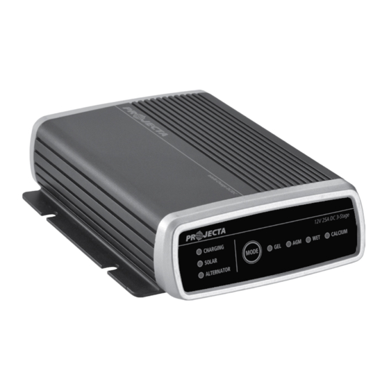
Page 5: Product Overview
PRODUCT OVERVIEW Charging LED Indicates charging status Mounting Slots DC Leads Temperature Solar LED Alternator Battery LED Battery Sensing Cable Indicates solar LED Indicates Chemistry Chemistry Display input status alternator input Selection Indicates selected (Mode) Button status battery chemistry type 63.5 Ø5.3... - Page 6 “Electrical System Memory Protector” be used. 2. Connect the Auxiliary Battery positive (+) terminal to the Output Cable (grey colour) from IDC25. Fit a 50A fuse to the cable as close as possible to the Auxiliary Battery positive (+) terminal.
- Page 7 6. When 12V solar panels are present, connect the solar panel positive terminal (+) to the IDC25 Solar Input cable (green colour). Fit a 50A fuse to the cable as close as possible to the Solar Panel positive (+) terminal.
- Page 8 Keep pressing the button momentarily until the Battery Chemistry LED you want is flashing. After you release the button, your selection is entered and saved. Your selection will be restored automatically even after the IDC25 is fully disconnected and reconnected. The default Battery Chemistry is AGM.
- Page 9 TYPICAL WIRING INSTALLATION 1. Full System LED Panel Mount Indicator For vehicles fitted with a Smart Alternator only Earth/Chassis Fuse Fuse Ground/Chassis Earth/Chassis Battery 1 Battery 2 Temp Sensor mount (Starter Battery) (Aux Battery) to battery casing 12V Solar Panel Earth/Chassis * Optional...
- Page 10 2. Alternator/Starter Battery Input Only LED Panel Mount Indicator For vehicles fitted with a Smart Alternator only Earth/Chassis Fuse Fuse Ground/Chassis Earth/Chassis Battery 1 Battery 2 Temp Sensor mount (Starter Battery) (Aux Battery) to battery casing * Optional...
- Page 11 3. Solar Battery Input Only LED Panel Mount Indicator Earth/Chassis Fuse Earth/Chassis Battery 2 Temp Sensor mount (Aux Battery) to battery casing 12V Solar Panel Earth/Chassis * Optional...
- Page 12 HOW TO READ LED DISPLAY 12V 25A DC 3-Stage CHARGING MODE CALCIUM SOLAR ALTERNATOR LED Charge Indicators Charging LED Battery Type LED Charging Stage GREEN Flashing Solid BLUE Bulk Charge GREEN Flashing BLUE Flashing Adsorption Charge Solid GREEN BLUE Flashing Equalization Charge Solid GREEN Solid BLUE...
-
Page 13: Frequently Asked Questions
This can occur if a small amount of power is used for a long time, for example a map reading light is left on for a week or more. The IDC25 is designed to charge an auxiliary battery from as little as 5 Volts. If the voltage is lower than 5 Volts use a pair of booster cables to connect between two batteries to provide more than 5 Volts to the battery being charged. - Page 14 Q. What is Surface Charge? A. Batteries unused or left discharged for some time build up a resistance to being recharged. When the charger is first connected, these batteries will take a surface charge, and the ‘FULLY CHARGED’ LED will illuminate within a short period of time.
- Page 15 NOTES...
- Page 16 WARRANTY STATEMENT Applicable only to product sold in Australia Brown & Watson International Pty Ltd of 1500 Ferntree Gully Road, Knoxfield, Vic., telephone (03) 9730 6000, fax (03) 9730 6050, warrants that all products described in its current catalogue (save and except for all bulbs and lenses whether made of glass or some other substance) will under normal use and service be free of failures in material and workmanship for a period of one (1) year (unless this period has been extended as indicated elsewhere) from the date of the original purchase by the consumer as marked...
Need help?
Do you have a question about the IDC25 and is the answer not in the manual?
Questions and answers