Table of Contents
Advertisement
Advertisement
Table of Contents

Related Manuals for Metrologic SP5500 OptimusS Series


Summary of Contents for Metrologic SP5500 OptimusS Series
- Page 1 METROLOGIC INSTRUMENTS, INC. SP5500 OptimusS Series User’s Guide...
- Page 2 Copyright © 2006 by Metrologic Instruments, Inc. All rights reserved. No part of this work may be reproduced, transmitted, or stored in any form or by any means without prior written consent, except by reviewer, who may quote brief passages in a review, or provided for in the Copyright Act of 1976.
-
Page 3: Table Of Contents
Table of Contents Introduction Product Overview ...4 Scanner and Accessories...4 General Features and Characteristics Multifunctional Keypad ...6 The LCD Screen ...7 The Lithium Battery ...7 Installation Getting Started ...8 Basic Operation...9 Communication and Data Setup...9 Data Upload ... 11 System Module ...12 System Menu Options ...12... -
Page 5: Product Overview
Introduction Product Overview The SP5500 OptimusS Portable Data Terminals are robust and versatile scanning devices designed to provide exceptional performance, while enduring the demands of everyday use. The lithium-ion rechargeable battery provides the Optimus with more than 100 hours of operation. It is supported by a resourceful set of development tools, including a Windows-based program builder, “C”... -
Page 6: General Features And Characteristics
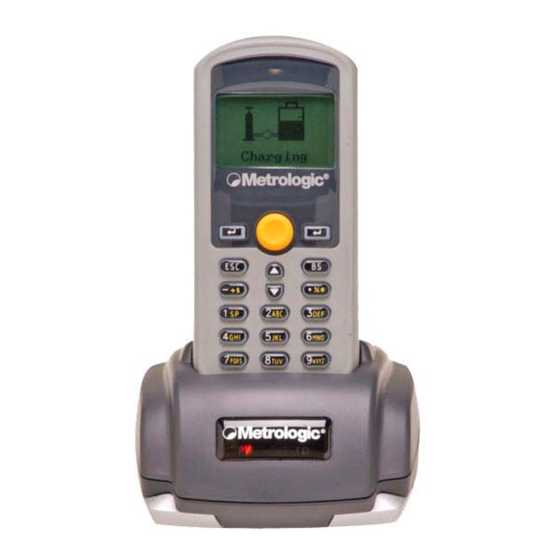
General Features and Characteristics Figure 1. Scanner Features Red Output Window (Laser Aperture) Safety and Product label (Figure 3) Speaker for audible indicators LCD display Multi-functional Keypad Charging and communication contacts IR Communication port Battery Compartment release Scan Button Figure 2. Cradle Features... -
Page 7: Multifunctional Keypad
Enter. There are two enter keys on the side of the scan key. Normally the enter keys are used for command execution or input confirmation. Scan a bar code. Pressing this button will trigger the scanner to read a bar code Escape. This key is used to stop and exit current operation Arrow.The two arrow keys located below the Scan key are used to toggle up and... -
Page 8: The Lcd Screen
General Features and Characteristics The LCD Screen The LCD screen of the OptimusS Portable Data Terminal displays program settings, operational parameters, data collected, and much more. The display is a graphical LCD with the following characteristics: Display area of 64 pixels x 100 pixels Resolution: Maximum of 8 lines x 16 characters Minimum of 4 lines x 12 characters... -
Page 9: Installation
Installation Getting Started The OptimusS Portable Data Terminal (PDT) requires minimal effort to begin functional operation for data collection in any application. In order to get started the unit must have a fresh battery inserted into the battery compartment. 1. Access the battery compartment by removing the battery cover (See Figure 7). To remove the cover, press the cover release down and slide the cover away form the unit. -
Page 10: Basic Operation
Installation Basic Operation In order for the Optimus to operate properly, an application program must be loaded onto the PDT. It is possible for the Optimus to power up without at active application. On power up if the Optimus has no application program loaded, then the following Application Program menu options will appear on the display: PTIONS... - Page 11 Installation 3. Follow steps a and b a. For the RS232 cable plug the 9 pin serial connector into a serial port on the host device. Plug the opposite end into the communication port of the cradle. b. For the USB cable plug the USB end of the cable into an appropriate communication port on the host device and the opposite end of the cable into the communication port of the cradle*.
-
Page 12: Data Upload
Installation Data Upload 1. To transfer the data collected select the Utilities option. 2. Select the Transfer Files option on the next menu and then the Send Files option. 3. Re-insert the Optimus unit into the cradle and upload the data to the host device. The OptimusSBT Bluetooth model is similarly connected to the host device and programmed however, there are some key differences in the data collection process. -
Page 13: System Module
Installation The System Module The system module on the Optimus is another useful tool included with the Optimus. It provides information about the Optimus and access to the system menu for configuring the Optimus. In order to access the system module, follow the instructions below: 1. - Page 14 The following table provides a description of the available tests. ETTING To test the reading performance of the scanner. The following symbologies are enabled for the Reader test. All other symbologies will need to be enabled via programming.
- Page 15 Installation Memory The menu option provides the user with ability to gather information on the amount of memory available on the Optimus, as well as the ability to initialize the memory. This is accomplished by choosing one of the two available selections. 1.
-
Page 16: Application
• The “BASIC” Compiler • The “C” Compiler For detailed information, please consult the appropriate manual or contact Metrologic Instruments, Inc.. Programming the communication cradle The communication cradle of the OptimusS Portable Data Terminal supports serial IR interface only. If a customized PC application has been developed for communication with the terminal via the cradle, it will be necessary to first configure the cradle through programming. -
Page 17: Troubleshooting
Cannot transmit data or programs to/from the terminal Keypad does not work properly Scanner does not scan Abnormal responses Make sure the battery is inserted and charged. Charge the battery and check the charging status. If no charging information shown on the display, reload the battery and check if the battery is properly installed then try again. -
Page 18: Specifications
Specifications PERATIONAL Light Source: Normal Depth of Field: Width of Scan Field: Single-Line Scan Speed: No. of Scan Lines: Min Bar Width: Decode Capability: Print Contrast: No. Characters Read: Beeper Operation: CPU: Program Memory: Data Memory: Display: Display Resolution: Bluetooth Version: Bluetooth Profiles: Communication (Unit): Communication (Cradle):... - Page 19 Specifications ECHANICAL Width (Unit): Depth (Unit): Height (Unit): Weight (Unit): Width (Cradle): Depth (Cradle): Height (Cradle): LECTRICAL Battery Operation: Battery Backup: Operation: Laser Class: EMC: NVIRONMENTAL Operating Temperature: Storage Temperature: Humidity: Shock Resistance: 55 mm (2.2") 28 mm (1.1") 137 mm (5.4") 4.9 oz (140 g) –...
-
Page 20: Contact Information And Office Locations
Via Emilia 70 40064 Ozzano dell’Emilia (BO) Tel: +39 0 51 6511978 Fax: +39 0 51 6521337 Email: info@it.metrologic.com Poland Metrologic Instruments Poland Sp.z o.o Poleczki 21 02-822 Warsaw, Poland Tel: +48 (22) 545 04 30 Fax:+48 (22) 545 04 31 Email:info@pl.metrologic.com... - Page 21 C/ Alfonso Gomez, 38-40, 1D 28037 Madrid Tel: +34 913 751 249 Fax: +34 913 270 437 United Kingdom Metrologic Instruments UK Ltd 58 Tempus Business Centre Kingsclere Road, Basingstoke Hampshire RG21 6XG Tel: +44 (0) 1256 365900 Fax: +44 (0) 1256 365955 Email: info@uk.metrologic.com...
-
Page 22: Safety Notices
Safety Notices This equipment has been tested and found to comply with the limits for a Class B digital device, pursuant to Part 15 of the FCC Rules. These limits are designed to provide reasonable protection against harmful interference in a residential installation. This equipment generates, uses, and can radiate radio frequency energy and, if not installed and used in accordance with the instructions, may cause harmful interference to radio communications.
Need help?
Do you have a question about the SP5500 OptimusS Series and is the answer not in the manual?
Questions and answers