Table of Contents
Advertisement
HORIZONTAL
ELECTRIC
7 TON LOG SPLITTER
MODEL NO.
ES7T20
Owner's Manual
ASSEMBLY & OPERATING INSTRUCTIONS
Purchase Date___________________ Serial No.______________________
Dealer________________________________________________________
Boss Industrial, Inc. • 123 Ambassador Drive, Suite 123 • Naperville, IL 60540 • USA
Phone: (800) 780-BOSS (2677) • Fax (331) 472-2976
www.boss-industrial.com
Rev.2
Advertisement
Table of Contents

Summary of Contents for Boss ES7T20
- Page 1 7 TON LOG SPLITTER MODEL NO. ES7T20 Owner’s Manual ASSEMBLY & OPERATING INSTRUCTIONS Purchase Date___________________ Serial No.______________________ Dealer________________________________________________________ Boss Industrial, Inc. • 123 Ambassador Drive, Suite 123 • Naperville, IL 60540 • USA Phone: (800) 780-BOSS (2677) • Fax (331) 472-2976 www.boss-industrial.com Rev.2...
- Page 3 We want to ensure your complete satisfaction at all times. Boss Industrial reserves the right to discontinue, change, and improve its products at any time without notice or obligation to the purchaser. The description and specifications contained in the manual were in effect at printing. Equipment described within this manual may be optional.
-
Page 4: Table Of Contents
Table of Contents Page(s) Important Safety Information ............................1-6 Intended Use ...............................1 Personal Protective Equipment ........................1 Safety Decals ............................1-4 Electrical Safety ............................5 Log Splitter Overview ...........................6 General Safety .............................7 Work Area ..............................8 Operation of Log Splitter ..........................8 Maintenance Safety .............................9 Hydraulic Safety ............................10 Fire Prevention ............................10 Assembly Instructions ............................11-12 Pre-Operation Instructions ..........................12... -
Page 5: Important Safety Information
SAFETY DECALS SAFETY DECALS Make sure that all safety warning decals are in good condition and readable. Always replace missing or defaced decals. Contact Boss Industrial, Inc. at 1-800-780-2677 for replacement decals. Page │ 1 Page | 1... - Page 6 Part #: 410-231 Part #: 410-156 Part #: 410-359 Part #: 410-159 Part #: 410-561 Part #: 410-602 Part #: 410-265 Part #: 410-245 Page | 2...
- Page 7 Some of the following symbols may be used on this tool. Please study them and learn their meaning. Proper interpretation of these symbols will allow you to operate the tool better and safer. SYMBOL NAME DESIGNATION/EXPLANATION Volts Voltage Amperes Current Hertz Frequency (cycles per second) Watt...
- Page 8 The following signal words and meanings are intended to explain the levels of risk associated with this product. SYMBOL SIGNAL MEANING Indicates an imminently hazardous situation, which, if not avoided, will result DANGER: in death or serious injury. Indicates a potentially hazardous situation, which, if not avoided, could result WARNING: in death or serious injury.
-
Page 9: Electrical Safety
ELECTRICAL CONNECTION ELECTRICAL CONNECTION ELECTRICAL SAFETY This tool is powered by a precision built electric motor. It should be connected to a power supply that is 115 volts, EXTENSION CORDS AC only (normal household current). Do not Use only 3-wire extension cords that have 3-prong operate this tool on direct current (DC). -
Page 10: Log Splitter Overview
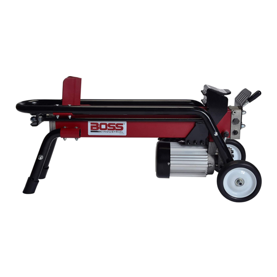
LOG SPLITTER OVERVIEW (FIGURE 1). 1. End wedge 8. On/Off switch 2. Sliding ram 9. Electrical cable with plug 3. Support legs, log holder 10. Oil drain bolt with dipstick 4. Machine body / Oil reservoir 11. Vent plug 5. Control handle 12. -
Page 11: General Safety
IMPORTANT SAFETY INFORMATION GENERAL SAFETY Failure to follow these instructions may result in serious injury or death. ALWAYS read the operator’s manual before operation. NEVER allow children to operate this log splitter. NEVER allow adults lacking proper instructions and understanding to operate this log splitter. KEEP all people and pets a minimum of 25 feet away from your work area when operating this log splitter. -
Page 12: Work Area
WORK AREA NEVER operate the log splitter on slippery, wet, muddy or icy ground. ONLY operate your log splitter on level ground. Operating on a slope could cause the log splitter to roll over or logs to fall off. NEVER attempt to move your log splitter over hilly or uneven terrain. ALWAYS block the wheels to prevent movement of the log splitter while in operation. -
Page 13: Maintenance Safety
OPERATION OF LOG SPLITTER KNOW how to stop the log splitter and disengage the controls before operating it. NEVER place hands or feet between the log and splitting wedge during forward or reverse stroke. Serious injury or death could result. NEVER straddle or step over the log splitter during operation. -
Page 14: Hydraulic Safety
HYDRAULIC SAFETY The hydraulic system of your log splitter requires careful inspection along with the mechanical parts. Be sure to replace frayed, kinked, cracked or otherwise damaged hydraulic hoses or hydraulic components. NEVER check for leaks of hydraulic fluid with your hand. Fluid escaping from a small hole can be almost invisible. Escaping fluid under pressure can have sufficient force to penetrate skin causing serious personal injury or even death. -
Page 15: Assembly Instructions
UNPACKING & ASSEMBLY \UNPACKING This product has been shipped pre-assembled (see FIGURE • Carefully remove the log splitter and all accessories from the box. Make sure that all items listed in the packing list are included. • Inspect the tool carefully to make sure no breakage or damage occurred during shipping. •... -
Page 16: Pre-Operation Instructions
PRE-OPERATION INSTRUCTIONS Log preparation Logs should be cut with square ends. Never split logs larger than 10 in. diameter or 20-1/2 in. WARNING: long. Uneven logs (e.g. knotted, curved, etc.) should not be used. Do not allow familiarity with tools to make you care- less. -
Page 17: Operating Instructions
OPERATING INSTRUCTIONS Plug the unit into a 3 prong outlet. Press the power button to turn the log splitter on. Place the log firmly against the wedge. (FIGURE 5). Move control handle down to split the log. Release the handle to retract the ram automatically and begin loading the next log. -
Page 18: Transportation
SPLITTING LOGS See FIGURE 5. WARNING: Always place logs lengthwise on the work table and resting firmly on the side supports with one end against the wedge. Never keep pressure on the wood by trying to force the Place logs flat and in the direction of the grain. Never angle log splitter for more than three seconds. -
Page 19: Maintenance
MAINTENANCE REPLACING HYDRAULIC OIL WARNING: See FIGURES 6, 7, 8, 9. The hydraulic oil in the log splitter should be changed every When servicing, use only identical replacement parts. 100 hours of use. Use of any other parts may create a hazard or cause product damage. - Page 20 Page │ 15 FIGURE 6. FIGURE 7. Drain Oil from Reservoir Note Acceptable Oil Fill Level FIGURE 8. FIGURE 9. Remove the control handle lever and Place Log Remove U-Joint and Refill Oil to Desired Level Splitter In Vertical Position Page | 16 Page │...
-
Page 21: Troubleshooting
TROUBLESHOOTING Problem Possible Cause Solution • Overload Protection Device is • Switch off the motor and unplug Motor fails to start. disengaged to protect the log the power cable. Let motor cool splitter from being damaged. down for 5 min and restart. If this does not solve the problem, call your dealer for customer support. -
Page 22: Technical Specifications
TECHNICAL SPECIFICATIONS Electrical requirements 115V, 60Hz Power output 1500W Rated current 13.5A Motor speed 3400 RPM Power cable SJTW 14 AWG (2.08mm²) Max splitting force 7 ton Max splitting length 20.5 in Max splitting diameter 10 in Hydraulic pressure 3500 PSI Cylinder bore 2.2 in Feed... -
Page 23: Exploded Diagram & Parts List
EXPLODED DIAGRAM & PARTS LIST Page │ 19 Page | 19... - Page 24 REF # PART # PART NAME SPECIFICATIONS QTY PER SECTION 310-325 Machine Body w/ End Wedge 7 ton 530-101 Ram Cap & Shaft 530-475 Upper Nylon Cushion 530-898 Lower Nylon Cushion 530-616 Base Plate of Ram 750-520 Flat Washer Black Oxide, M10*1.5 750-355 Spring Washer Black Oxide, M10*3...
- Page 25 REF # PART # PART NAME SPECIFICATIONS QTY PER SECTION 710-896 Oil Tube Screw Black Oxide, M14*30*1.5 540-311 Oil Filter 710-541 Inner Hex Head Bolt Black Oxide, M8*30 750-075 Spring Washer Black Oxide, M8*2.5 750-160 Flat Washer Black Oxide, M8*1 910-256 Electric Motor 2 HP 910-194...
-
Page 26: Warranty Information
BOSS brand product. Proof of purchase will be required by the dealer to substantiate any warranty claim. -
Page 27: Packing List
PACKING LIST (1) Log Splitter (1) Owner’s Manual (1) Control handle lever w/ grip (1) Hex Key 6mm (1) Copper seal washer M14*1 Page │ 23 Page | 23... - Page 28 Boss Industrial, Inc. • 123 Ambassador Drive, Suite 123 • Naperville, IL 60540 • Phone: (800) 780-BOSS (2677) • Fax (331) 472-2976 www.boss-industrial.com Page | 24...
Need help?
Do you have a question about the ES7T20 and is the answer not in the manual?
Questions and answers