Table of Contents
Advertisement
Chapter 1. Overview ................................................................................. 3
1.1. Equipment ............................................................................. 3
1.2. Features ................................................................................ 3
1.2.1. Scanner ............................................................... 3
1.2.2. Display Unit .......................................................... 3
1.3. Composition ........................................................................... 3
1.4. Construction ........................................................................... 3
1.5. Specifications ......................................................................... 4
1.5.1. General ................................................................ 4
1.5.2. Scanner (RSU-3700) ............................................. 4
1.5.3. Display Unit (SMR-3700) ....................................... 5
1.5.4. Connection Cable .................................................. 5
Chapter 2. How it works ............................................................................ 6
2.1. What is Radar ? ........................................................................ 6
2.3. Measurement of Radar.............................................................. 6
2.4. Measurement of a Course ......................................................... 6
2.5. Speed of Radar waves & Antenna rotation ................................. 6
2.6. Radar Display ........................................................................... 6
Chapter 3. How to operate panel and menu ............................................. 7
3.1. Front Panel Buttons and Knob ................................................... 7
3.1.1. Front Function ........................................................ 7
3.1.2. Directional Key ....................................................... 8
3.1.3. Display Characters .................................................. 8
3.2. Display Description ................................................................... 8
3.3. Menu Functions ........................................................................ 9
3.3.1. Menu Composition .................................................. 9
3.3.2. MENU Functions ................................................... 11
Chapter 4. How to operate the unit ......................................................... 13
4.1. General Idea .......................................................................... 13
4.1.1. Power Input and Operation ................................... 13
4.1.2. Tuning Control ...................................................... 13
4.1.3. Image Control ...................................................... 13
4.1.4. Power Off ............................................................. 13
4.2. Stand-by for Processing .......................................................... 13
4.2.1. Brightness Change ................................................ 13
4.2.2. Language Selection ............................................... 13
4.3 Basic Operation ....................................................................... 13
4.3.1. TX ....................................................................... 13
4.3.2. TX Stop ................................................................ 13
4.3.3. Tuning Control ...................................................... 13
4.3.4. Gain Control ......................................................... 14
4.3.5. Rain/Snow Removal .............................................. 14
4.3.7. To operate the alert function .................................. 15
4.3.8. To eliminate/display the scale of Range Ring .......... 16
4.3.9. To remove the Radar Interference ......................... 16
4.3.10. To eleminate the Ship's Heading Line ................... 16
4.3.11. To use the parallel line ........................................ 17
4.3.12. To move the center of own ship ........................... 17
4.3.14. To change distance unit....................................... 18
4.3.15. To change the way of direction symbol ................. 18
4.3.16. To change the way of bearing display................... 19
4.3.17. To change the way of displaying bearing ine/cursor19
Contents
1
SMR-3700 New Rev.1.0(071204)
Advertisement
Table of Contents

Related Manuals for Samyung SMR-3700


Summary of Contents for Samyung SMR-3700
-
Page 1: Table Of Contents
1.4. Construction ................3 1.5. Specifications ................. 4 1.5.1. General ..............4 1.5.2. Scanner (RSU-3700) ..........4 1.5.3. Display Unit (SMR-3700) ........5 1.5.4. Connection Cable ..........5 Chapter 2. How it works ................6 2.1. What is Radar ? ................ 6 2.2. - Page 2 4.3.18. To compensate the magnetic ....... 20 4.3.19. To measure the time to the target......20 4.3.20. To display the Waypoint ........20 4.3.21. To display the other ship’s track line ..... 20 4.3.22. To make intermittant transmittion for suppressing electric power of Radar..21 4.3.23.
-
Page 3: Chapter 1. Overview
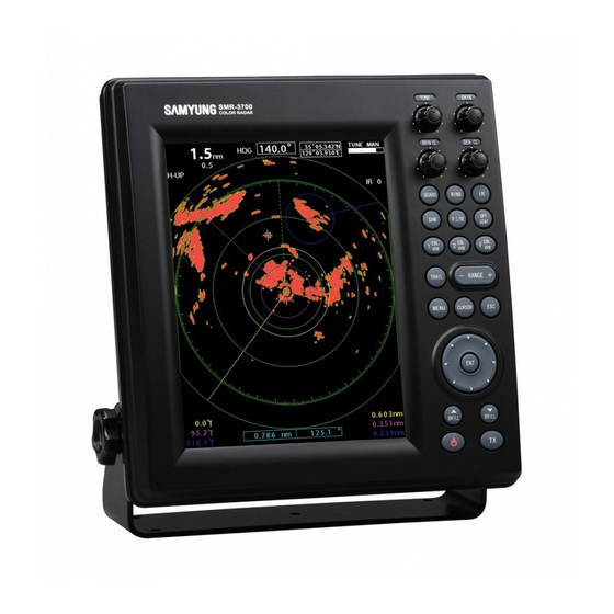
1.1. Equipment SAMYUNG DESCRIPTION Qt’ REMARKS CODE SMR-3700 type radar is a small-sized raster scanning Radar, which composes Radom type transceiver with MANUAL SMR-3700-ME 4 KW Transmitting power and 10.4 inch color TFT SCANNER- LCD monitor. Completely sealed case offers one-step... -
Page 4: Specifications
COLOR : DARK-GRAY, MASS : APPROX. 5.8Kg, UNIT : mm <Drawing 1.2> External Diagram of SMR-3700 DISPLAY 1.5. Specifications 1.5.2. Scanner (RSU-3700) 1.5.1. General (1) Dimentions (1) Display Type : Raster Scan Type a) Diameter : 590mm (2) Display Screen :10.4”... -
Page 5: Display Unit (Smr-3700)
1.5.3. Display Unit (SMR-3700) (1) Dimensions f) Distance Circle : Switch a) Width : 290mm g) Interference Rejection: Switch b) Height : 300mm h) Heading Line : Switch c) Depth : 142mm i) Parallel Line : Switch (2) Construction : Desk Type... -
Page 6: Chapter 2. How It Works
Chapter 2. How it works 2.1. What is Radar ? 2.4. Measurement of a Course Radar stands for Radio Detection And Ranging. One way to measure the distance to an object is Radar was developed its principles while World War transmit short pulse... -
Page 7: Chapter 3. How To Operate Panel And Menu
Chapter 3. How to operate panel and menu 3.1. Front Panel Buttons and Knob It is available to display and adjust the various data on the screen by using the the control keys as follows; (1) Dedicated 4 (Four) Volumes (2) Directional key for 8 (Eight) directions and center key for moving to the display center (3) Dedicated 19 (Nineteen) keys (4) Available to select every function in Menu... -
Page 8: Directional Key
3.1.2. Directional Key Tey are used to move the cursor, turn the EBL, change the VRM size and move to any of the sub-menu. They are used to operate the following functions. 3.1.3. Display Characters How to operate the exclusive keys Display Descptions Position... -
Page 9: Menu Functions
3.3. Menu Functions In addition to the functions used by the front panel keys, SMR-3700 has the functions to enable user to control with menu. 3.3.1. Menu Composition It is available to converse the display language to Korean, English. Russian, Chiness. - Page 10 (2) Initial Setup Menu for installer At INIT. SET of ‘MENU’, press button, the following display will appear. For any additional item, please refer to ‘6.6 Initial Setup by Installer’. Initial Setup by Installer Additional Item...
-
Page 11: Menu Functions
3.3.2. MENU Functions To use the functions attached with ‘※’, it is required to get connected with external navigational device FUNC/DISPLAY RADAR SET-UP TUNING MODE : To select ‘Automatic’ or ※HEADING MODE : To select the display of the ‘Manual’. - Page 12 INIT. SET Initial Setup by Installer COLOR SET : To set up PPI image color. LANGUAGE SET : To set up the language in use. BEARING ADJUST : To adjust the PPI image bearing SIMULATION : To show the simulation. DISPLAY TIMING : To adjust the PPI image OUTSIDE COLOR : To set up the external distance.
-
Page 13: Chapter 4. How To Operate The Unit
Afte power on, Count Down Timer is displayed 4.1.4. Power Off on SAMYUNG Logo screen, it is converted to (1) TX stop. the stand-by in 1 min. 30 secs. c) As the TX time is consolidated and displayed, ... -
Page 14: Gain Control
4.3.4. Gain Control ATTENTION ※ It should be always observed by adjusting the optimum conditions. ※ If the gain is too low, the targets may not be displayed. ※ If too high, it may be an obstacle in observation due to the noise increase on the PPI display. -
Page 15: To Remove The Interference Of Sea Level Wave Caused By The Sea Wave
4.3.6. To remove the interference of Sea Level Wave caused by the Sea Wave ATTENTION ※ If you set the removal function of Sea Level Wave up to removal of all Sea Level Reflection at short distance, it causes intereference in detecting images due to the target of vessel and dangerous things as well as the wave images being suppressed. -
Page 16: To Eliminate/Display The Scale Of Range Ring
(2) Change of the alert level (1) Whenever pressing button, it marks with IR-1, IR-2, IR-3 in order in the top-right screen. Menu screen Move to RADAR SET-UP IR-3 status that shows Radar interference a lot. (IR=INT REJECT) Move to ALARM LEVEL , press Radar interefence Move to 1 / 2 / 3 / 4 / 5 / 6 / 7 , press... -
Page 17: To Use The Parallel Line
4.3.11. To use the parallel line (3) How to measure bearing & distance from a target to target by using F EBL/VRM Length-parallel line for distance and function. width-paralled line for bearing are VRM & EBL are shown at the top- shown as one line at PPI screen and the bearing &... -
Page 18: To Change Distance Unit
4.3.14. To change distance unit Menu screen Move to FUNC/DISPLAY SET Move to DISTANCE UNIT , press Move to NM / KM / KM-River, press Back to PPI screen (1) NM(Mile, Nautical Mile) Cusor, VRM, Distance of Parallel Line represents NM. <PPI image moves counterclockwise.>... -
Page 19: To Change The Way Of Bearing Display
(3) COURSE-UP a) Make the ship’s head bearing always indicate 4.3.16. To change the way of bearing Course-up when the course is set. display b) Even though ship’s head direction is changed, ECHO image bearing does not change but Menu screen ship’s head moves as much as the variation of Move to FUNC/DISPLAY SET ship’s head bearing. -
Page 20: To Compensate The Magnetic
4.3.18. To compensate the magnetic 4.3.20. To display the Waypoint Input the value of compensation because To use this function, it needs the input of bearing Magnetic North Bearing is little bit different data, distance data to go waypoint and own ship’s according to the Navigation zone. -
Page 21: To Make Intermittant Transmittion For Suppressing Electric Power Of Radar
Back to PPI screen 4.3.22. make intermittant transmittion for suppressing electric 4.3.23. To display ECHO image long power of Radar. on PPI screen. ATTENTION CAUTION ※ Pay consideration to the surrounding condition When designating target ※ as there is high potentiality in collision with a magnification and wider tranmit pulse fast moving dangerous thing or vessels when width, the images over two targets... -
Page 22: Other Convenient Function
(2) Set the outside color Black / Blue The outside color of PPI image not displayed is (Move / select for desirable colors) changed. Back to PPI screen Menu screen Move to INIT. SET 4.4. Other convenient function Move to OUTSIDE COLOR, 4.4.1. -
Page 23: Chapter 5. Screen View
Chapter 5. Screen view 5.1. The distance from the target to the height of target The longest distance observable to the target is depending on the height of target, the distance to the target and the height of antenna other than the matter of performance like Tx power, Antenna beam width and receiving sensitivity. -
Page 24: Wave Path
5.3. Wave Path In case there is an obstruction in the course of wave path like Mountain, Rain and Snow, the target behind of them may not be observed. The target does not appear due to 우설과 산으로 가려져 물표가 SNOW and Mountain. -
Page 25: Chapter 6. Installation
Chapter 6. Installation CAUTION ※ The specialist from Head Office or Local distributor should carry out installation work. ※ Installation works carried out by unauthorized person can cause out of order, performance failure Electric shock. 6.1. Overview Proper installation of Radar ensures the performance and safety of it during operation and facilitates the maintenance and repair of it, you should carefully pay attention to the proper of installation accoding to the instruction. -
Page 26: Connection To Equipment Cable
6.2.3. Connection to Equipment cable (1) SCANNER (RSU-3700) Motor Heading sensor Rx power and video signal (Connected Display) Motor power supply Bearing sensor Tx power supply (Connected Display) Heading signal Rx power supply ATTENTION ※ Fix the cable with tie. ※... -
Page 27: Display Set-Up
6.3. DISPLAY SET-UP 6.6. Initial Installation 6.3.1. Location for installation In case of a first time, it must be executed an initial adjustment. ATTENTION 6.6.1. Initial Installation ※ A display must be installed far away over than In order to shift Initial Installation Menu,at INIT. 1 meter from a magnet compass. -
Page 28: Tune-R Set (Tuning Set)
6.6.2. TUNE-R SET (Tuning Set) Wait for approx. 5 min. in a PPI screen. (Adjust after magnetron is enough preheated) Put it to a center Set it to Max Set it to Minimum . Menu screen Move to RADAR SET-UP Move to TUNING MODE, press Move to Manual, press Move to INIT. -
Page 29: Tune Set (Tune Level Set)
6.6.3. TUNE SET (Tune Level Set) TUNE-R setting should be finished completely. Menu screen Move to INIT. SET Push bottons one after another, It is displayed additional menu out of default(settion) menu. Move to TUNE SET, Select, PPI screen comes up and displayed number in the middle of top screen. -
Page 30: Bearing Adjust (Bearing Set)
6.6.4. BEARING ADJUST (Bearing Set) An adjust to fix a real bearing for a target in a PPI screen. (In a transmitting) 0.25 Menu screen Move to INIT. SET Push bottons one after another, It is displayed additional menu out of default(settion) menu. -
Page 31: Display Timing (0 Mile Set)
6.6.5. DISPLAY TIMING (0 Mile Set) (1) An adjust to fix a real distance and target distance of the PPI screen. (In a transmitting) (2) If the real distance is 0.2NM for non-moving target, while the PPI target is marked on 0.18NM, adgust it as followings. -
Page 32: Gain-L Set (Gain Set)
6.6.6. GAIN-L SET (GAIN SET) A function to adjust a Gain of the PPI screen. (In a transmitting) Put it to a center. Set it to Max. Set it to Minumum. Set it to 6NM for distance range. Menu screen Move to INIT. -
Page 33: Stc-H Set (Sea Clutter Set)
6.6.7. STC-H SET (Sea Clutter Set) Adjust distance for removal sea reflection to identify targets marked as small spots. (In a transmitting) Set it to Max. Set it to Minimum Set it to Max. Set it to 6NM for distance range Menu screen Move to INIT. -
Page 34: Mbs Set
6.6.8. MBS SET (1) MBS = Main Bang Suppression 0.125 0.25 (2) It may be Main Bang phenomenon in a center of the indicator in a short range and can be suppressed as followings. (In a transmitting) Adjust it till the noise is suppressed. Adjust it with optimum. -
Page 35: Chapter 7. Maintenance
Chapter 7. Maintenance 7.1. General Maintenance 7.2. Scanner (1) In order to get Radar performed in good order, When maintained a wireline, cut off the power of a periodical maintenance should be done properly. monitor and then protect the power supplied into (2) The unexpected troubles would be less by the wireline. -
Page 36: Chapter 8. Packing List
Chapter 8. Packing List SMR-3700 ( 36Mile Marine RADAR) Q’ty Ch. Item External Drawing Dimension Remark SMR-3700 Display CODE NO. SMR-3700 Bracket CODE NO. ACC-RADAR-001 Ø 6 × 20 Knob CODE NO. ACC-6X18MM-002 RSU-3700 Scanner CODE NO. RSU-3700 SAMYUNG Ø 11 X 16C... - Page 37 Ø 10 X 25 6Angle Bolt CODE NO. ACC-SC-001 Ø 10 Spring Washer CODE NO. ACC-WA-001 Ø 10 Plain Washer CODE NO. ACC-WA-002 Ø 50 Bottom CODE NO. ACC-PAD-001 Fuse CODE NO. ACC-FUSE-001 Manual CODE NO. SMR-3700-MK Scanner Dwg. Install’n CODE NO. RSU-3700-DK...
-
Page 38: Chapter 9. Installation Drawing And Circuit Diagram
Chapter 9. Installation drawing and circuit diagram...
Need help?
Do you have a question about the SMR-3700 and is the answer not in the manual?
Questions and answers